
Komatsu WA200-6 Wheel Loader Shop Manual SEN03081-02 (Serial 70001 and Up)
Original price was: $39.95.$23.95Current price is: $23.95.
Komatsu WA200-6 Galeo shop manual for serial numbers 70001 and up, covering specifications, HST power train, hydraulics, failure-code troubleshooting, testing, and disassembly procedures.
Description
Komatsu WA200-6 Wheel Loader Shop Manual SEN03081-02 (Serial 70001 and Up)
The Komatsu WA200-6 Wheel Loader Shop Manual SEN03081-02 (Serial 70001 and Up) is the workshop volume written for the Galeo WA200-6 wheel loader from serial number 70001 onward. It gathers specification data, structure and function explanations, maintenance standards, testing and adjusting methods, failure-code and symptom troubleshooting, disassembly and assembly sequences, plus hydraulic and electrical drawings used on this hydrostatic-drive machine.
File Details
- Manual type: Shop manual (chassis volume)
- Brand / model: Komatsu Galeo WA200-6 wheel loader
- Serial range: 70001 and up
- Language: English
- Page count: 1235
- File format: PDF
- Binder / form number: SEN03081-02
- Index form: SEN03090-02
- Foreword form: SEN03091-00
- Printed in Japan 10-07 (01), copyright 2007 Komatsu
This file is the chassis shop manual. The text states that shop manuals are divided into a chassis volume and an engine volume, and that work on the engine unit itself is covered in the engine volume for the engine model mounted on the machine.
Machine Covered in This Edition
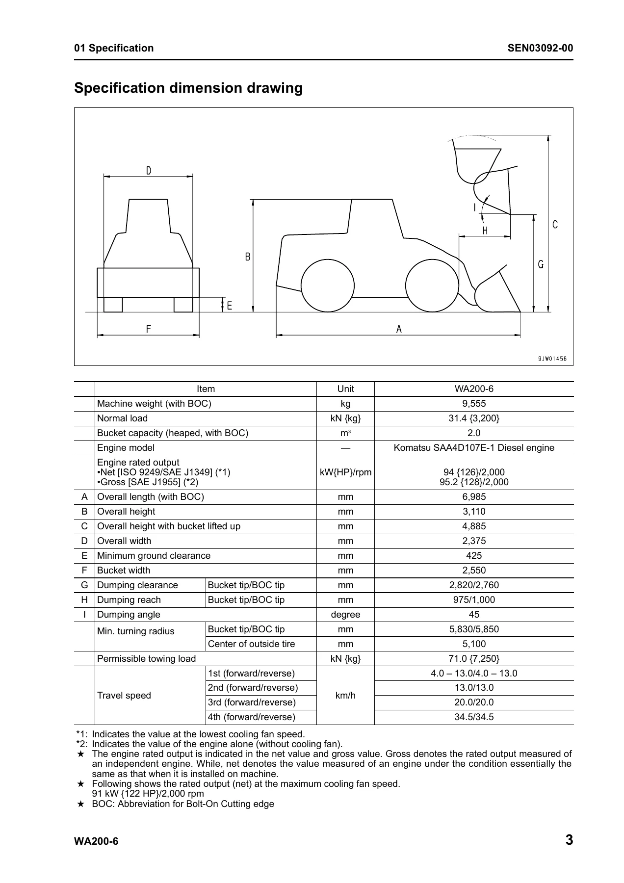
Coverage is limited to the WA200-6 with serial numbers 70001 and up. Specification pages list the mounted engine as the Komatsu SAA4D107E-1 diesel: a 4-cycle, water-cooled, in-line 4-cylinder, direct-injection engine with turbocharger and air-cooled aftercooler, cylinder bore x stroke 107 x 124 mm, and total piston displacement 4.46 L {4,460 cc}. Net rated output is given as 94 kW {126 HP} at 2,000 rpm (ISO 9249 / SAE J1349 at lowest cooling-fan speed) and gross output as 95.2 kW {128 HP} at 2,000 rpm (SAE J1995). Net output at maximum cooling-fan speed is listed as 91 kW {122 HP} at 2,000 rpm. Maximum torque is 584 Nm {59.6 kgm} at 1,400 rpm.
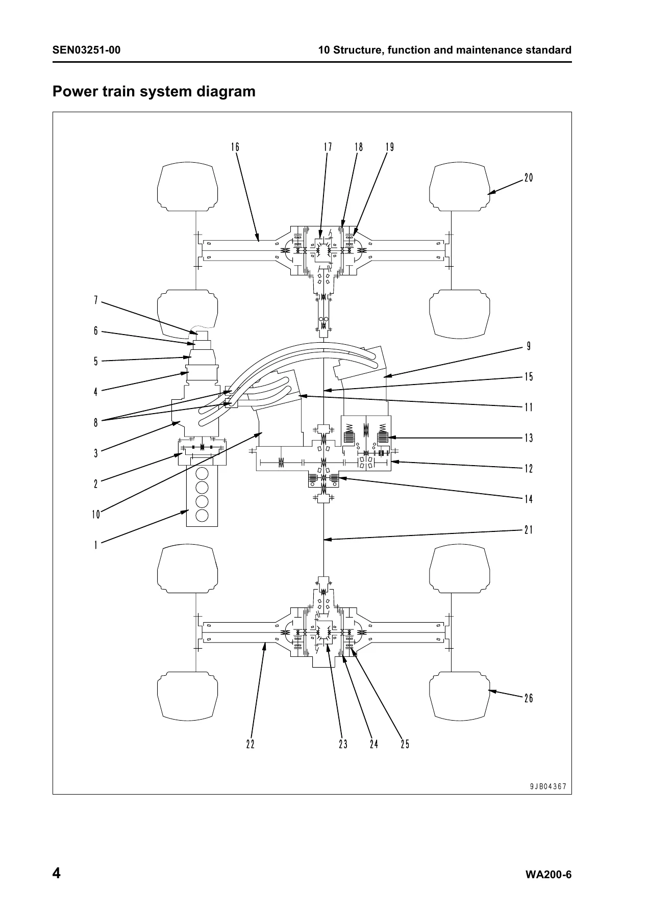
Machine weight with bolt-on cutting edge is 9,555 kg. Heaped bucket capacity with BOC is 2.0 m³ and normal load is 31.4 kN {3,200 kg}. Travel speeds are given in four ranges, 1st through 4th, forward and reverse, with 4th listed at 34.5 km/h. The power train is hydrostatic: a variable-displacement swash-plate piston HST pump driving two variable-displacement bent-axis piston HST motors through a transfer that switches between two power trains, then front and rear axles with torque-proportioning differentials and planetary final drives. Service brakes are enclosed wet multiple-disc units on all four wheels; the parking brake is a wet multiple-disc unit on the transfer output shaft. Steering is articulated-chassis hydraulic with an Orbit-roll valve. Work equipment uses a 2-spool control valve with a listed set pressure of 20.6 MPa {210 kg/cm²}.
Chapters Covered
- 00 Index and foreword — composition of shop manual; table of contents; safety notice; how to read the shop manual; explanation of terms for maintenance standard; handling of electric equipment and hydraulic components; handling of connectors newly used for engines; how to read electric wire code; precautions when carrying out operation; method of disassembling and connecting push-pull type coupler; standard tightening torque table; conversion table
- 01 Specification — specification dimension drawing; specifications; weight table; table of fuel, coolant and lubricants
- 10 Structure, function and maintenance standard — engine and cooling system (engine mount and transfer mount, damper, cooling system, cooling system hydraulic piping diagram, cooling fan motor); power train (system diagram, drive shaft, HST hydraulic piping diagram, HST pump, HST motor, transfer, clutch solenoid valve, axle, differential, torque proportioning differential, limited slip differential, final drive); steering system (piping diagram, steering column, priority valve, Orbit-roll valve, 2-way restrictor valve, cushion valve, steering cylinder, emergency steering piping and valve, steering relief valve); brake system (piping diagram, charge valve, brake valve, inching valve, accumulator, slack adjuster, brake, parking brake control and parking brake); undercarriage and frame (axle mount and center hinge pin); hydraulic system (work equipment hydraulic piping diagram, control lever linkage, hydraulic tank, 4-gear pump, work equipment control valve, PPC valve, lock valve, accumulators, ECSS valve); work equipment (linkage, bucket, bucket positioner and boom kick-out, work equipment cylinder); cab and its attachments (cab, air conditioner); electrical system Part 1 (machine monitor system and machine monitor); electrical system Part 2 (HST controller system, HST controller, ECSS system, KOMTRAX system, engine starting and stopping circuits, preheating circuit, engine output derating and automatic warm-up, parking brake circuit, max. traction switch, sensors)
- 20 Standard value table — standard service value table for engine; standard service value table for chassis
- 30 Testing and adjusting — Part 1 engine tests (speed, exhaust color, valve clearance, compression, blow-by, oil pressure, boost, fuel pressure and leakage, air bleed, belts); Part 2 chassis tests (accelerator and directional lever, HST oil pressure, clutch control pressure, steering wheel and steering oil pressure, hydraulic fan, brake pedal and performance, accumulator charge, wheel brake pressure and disc wear, parking brake, work equipment lever and hydraulic / PPC pressure, bucket positioner and boom kick-out, diodes, electric-system preparation, KOMTRAX terminal); Part 3 machine monitor adjustment, sensor and controller setup with the monitor, special functions of the machine monitor (EMMS), Pm clinic inspection chart
- 40 Troubleshooting — failure code table and fuse locations; general information on troubleshooting; troubleshooting by failure code Parts 1–7; troubleshooting of electrical system (E-mode); troubleshooting of hydraulic and mechanical system (H-mode); troubleshooting of engine (S-mode)
- 50 Disassembly and assembly — general information, coating materials, special tools; engine and cooling system (fuel supply pump, injectors, cylinder head, hood, radiator, aftercooler, hydraulic oil cooler, engine assembly, front and rear oil seals, cooling fan and fan motor, fuel tank); power train Parts 1 and 2 (transfer, parking brake, front and rear axles, axle housing, differential); undercarriage and frame (center hinge pin, counterweight); hydraulic system (HST pump and 4-gear pump, HST motors, work equipment control valve, hydraulic tank, hydraulic cylinder); work equipment assembly; cab and floor frame, stuck glass, air conditioner unit; electrical system (monitor panel, engine controller, HST controller, KOMTRAX terminal)
- 90 Diagrams and drawings — hydraulic circuit diagram; electrical circuit diagram; connector arrangement diagram
Taken together, the Komatsu WA200-6 Wheel Loader Shop Manual SEN03081-02 (Serial 70001 and Up) is the chassis workshop reference a technician uses to identify the machine, understand how each circuit works, compare measured values against new-machine and service-limit figures, run tests, interpret displayed failure codes, and remove or rebuild major assemblies.
Testing, Adjusting, and Standard Values
Section 20 lists standard service values for the SAA4D107E-1 engine and for the chassis. Engine speed examples include high idle 2,225 (+70/-50) rpm. Chassis tables cover directional-lever play and effort, steering-wheel play, operating effort and lock-to-lock turns, HST high-pressure cut-off and low-pressure relief, work-equipment relief pressure, and lift-arm cycle times. Section 30 then shows how to take those readings: measuring engine speed from the machine monitor (code 01001 ENG SPEED), exhaust color, valve clearance with the engine at normal temperature, compression with the monitor set to no-injection cranking, blow-by, engine oil pressure, intake-air boost, fuel low-pressure and return rates, HST stall and cut-off pressures, steering main relief, hydraulic-fan speed and drive pressure, brake-pedal travel and stopping performance, accumulator cut-in, wheel-brake pressure, brake-disc wear, parking-brake hold on a 1/5 grade, work-equipment and PPC pressures, and bucket-positioner / boom kick-out switch clearance of 3–5 mm.
The same testing chapters explain residual-pressure release in the fuel, brake-accumulator, and work-equipment circuits; air bleeding of steering, wheel-brake, and hydraulic circuits; handling of reduced-cylinder mode and no-injection cranking; and KOMTRAX terminal start-up and indicator-lamp checks. Special functions of the machine monitor (EMMS) include real-time monitoring, cylinder cut-out, no-injection cranking, optional-device selection, travel-speed unit (km/h or MPH on non-SI machines), and replacement-interval reminders such as engine oil at 500 hours.
Failure Codes and Symptom Troubleshooting
Section 40 is built around the codes the machine monitor, engine controller, and HST controller can display, plus three symptom trees. Failure-code chapters walk through examples such as [2G40GZ] brake oil-pressure reduction, [6091NX] HST filter clogging, [B@BAZG] engine oil-pressure reduction, [B@BCNS] engine overheat, [B@BCZK] low coolant level, CA-series engine-controller faults (Ne and backup speed sensors, charge pressure and temperature, throttle, coolant, common-rail pressure, injectors 1–4, IMV/IMA, battery voltage, intake-heater relay), HST-controller power and CAN faults, parking-brake switch circuits, FNR lever, travel-speed sensors, fan and clutch EPC solenoids, and overrun alarms for the steering pump, HST pump, and HST motor 1.
E-mode electrical charts cover a no-start condition, preheater operation, boom kick-out, bucket positioner, lift-arm FLOAT holding, travel-direction selection, wiper and washer, lamps, backup alarm and horn, alarm buzzer, air conditioner, and KOMTRAX. H-mode hydraulic and mechanical charts address a machine that will not start, slow travel, weak traction, engine stall while traveling, speed-range shift, steering that will not turn or is heavy or jerks, brake drag or fade, lift-arm and bucket speed or drift, ECSS pitch, and abnormal fan speed. S-mode engine charts cover poor starting, no start, poor pickup, stopping during work, rough running, lack of output, black or blue smoke, oil consumption and contamination, fuel use, oil in coolant, low oil pressure, rising oil level, overheating, noise, and vibration.
Disassembly, Special Tools, and Circuit Drawings
Section 50 lists coating materials and special tools (seal pullers for the engine front and rear oil seals, injector and cylinder-head tools, T-adapters for controller and sensor diagnosis) and then gives removal and installation sequences with tightening torques and refill quantities. Examples from the text include radiator coolant drain of about 17 L, fuel tank capacity of about 177 L when full, engine-mount bolts 235–285 Nm {23.5–29.5 kgm}, and hydraulic-tank refill after work-equipment or HST pump work. Section 90 supplies the hydraulic circuit diagram, the electrical circuit diagram, and the connector arrangement diagram used when tracing pins during the failure-code procedures.
Fluid capacities printed in the specification section include engine oil pan 17 L specified / 15.5 L refill, transfer case 6.5 / 5.0 L, hydraulic system 120 / 58 L, axle (front/rear) 18 L each, cooling system 17 L, and fuel tank 177 L. Electrical supply figures on the same pages are a 24 V, 4.5 kW starting motor, 24 V 60 A alternator, and two 12 V 88 Ah batteries.
Use This Manual on the Machine
With the Komatsu WA200-6 Wheel Loader Shop Manual SEN03081-02 (Serial 70001 and Up) a shop can set valve clearance, measure compression and fuel-system leakage, adjust HST cut-off and steering relief, bleed brakes and work-equipment circuits, diagnose a displayed CA or HST code, follow an E/H/S symptom chart, and pull the engine, HST pump, motors, axles, control valve, cab, or controllers using the published tool list and torque values. Those procedures and numbers matter because HST pressure, common-rail fuel hardware, wet brakes, and controller power supplies on this loader are specified to tight windows; guessing cut-off pressure or injector connector torque is how a repair creates the next failure code. After payment the file is delivered as an instant PDF download—no shipping—so it can be opened on a phone, tablet, or workshop PC and printed for the bench.
Reviews
There are no reviews yet.