
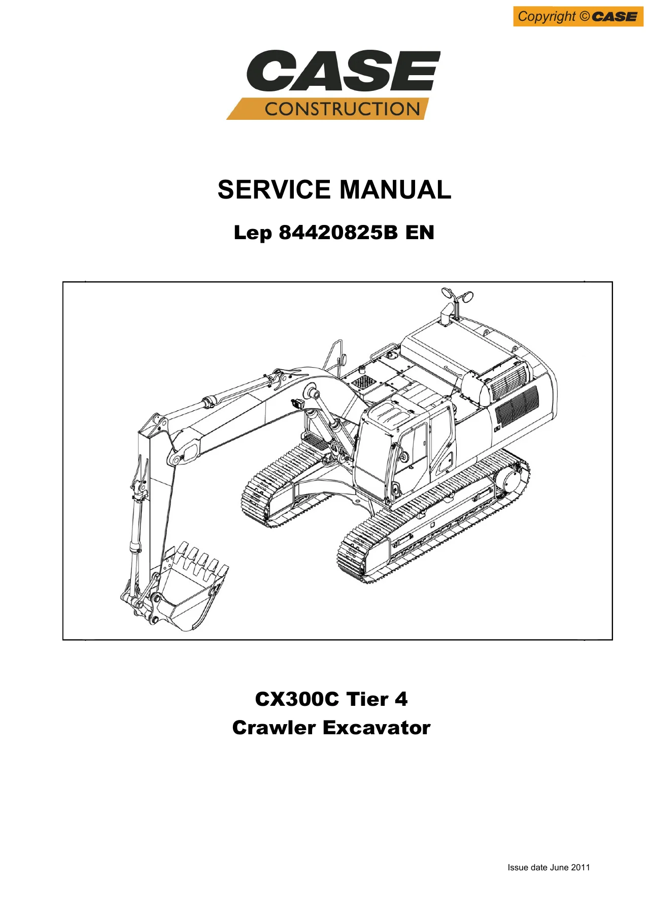
Case CX300C Tier 4 Crawler Excavator Service Repair Manual 2011
Original price was: $39.95.$24.95Current price is: $24.95.
Complete 2011-page Case CX300C Tier 4 Crawler Excavator Service Repair Manual (84420825B EN, June 2011). Covers engine, fuel system, electrical, undercarriage, drive train, hydraulics, uppermost structure, cab, air conditioning, and large-format schematics. Instant PDF download.
Description
Case CX300C Tier 4 Crawler Excavator Service Repair Manual
This is the complete Case CX300C Tier 4 Crawler Excavator Service Repair Manual, document number 84420825B EN, issued in June 2011. It covers the CX300C Tier 4 crawler excavator and the CX300C NLC variant, fitted with the Isuzu 6HK1X diesel engine. The manual is organized into ten major sections spanning 2011 pages: general information, engine, fuel system, electrical system, undercarriage, drive train, undercarriage hydraulics, uppermost hydraulics, uppermost structure and cab, and large-format schematics. Every procedure is written for technicians performing removal, installation, disassembly, assembly, inspection, adjustment, troubleshooting, and maintenance on this specific machine.
File Details
- Manual type: Service Manual (Workshop Manual)
- Brand: Case (CNH)
- Model: CX300C Tier 4 Crawler Excavator
- Language: English
- Page count: 2011 pages
- File format: PDF
- Document number: 84420825B EN
- Date: June 2011
Chapters Covered
- Section 1001: Safety, general information and standard torque data
- Section 1002A: Specifications
- Section 1002B: Main Equipment Table (CX300C)
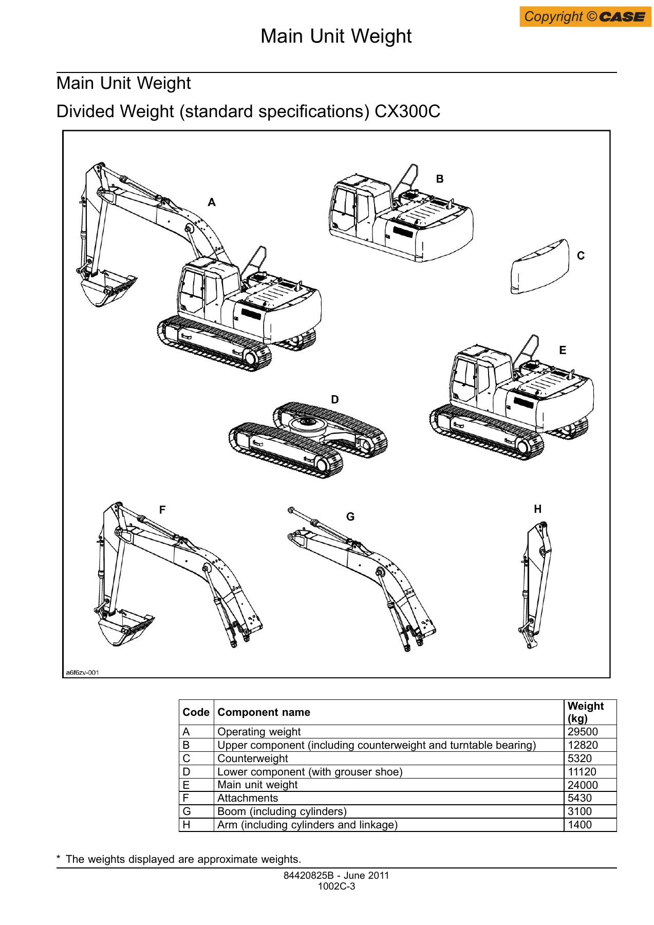
- Section 1002C: Main Unit Weight
- Section 1002D: Maintenance Standards
- Section 1002E: Bolt Size and Torque Table
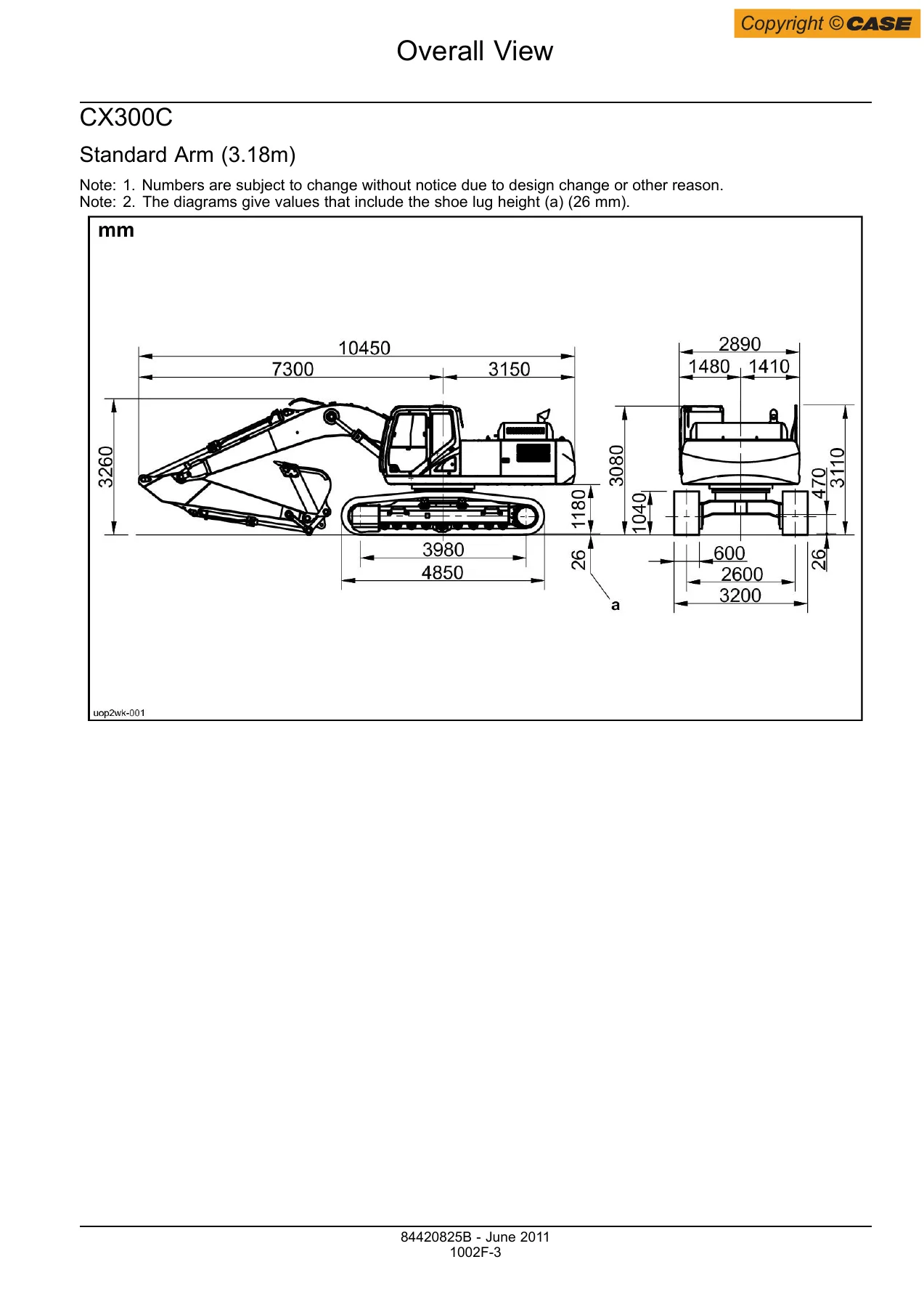
- Section 1002F: Overall View
- Section 1003: List of Special Tools
- Section 1004: Fluid and Lubricants
- Section 1005: Conversion Table
- Section 1900: Abbreviations
- Section 2000: Removal and Installation of Engine Assembly
- Section 2001: Removal and installation of the fuel cooler, engine inter-cooler radiator and oil cooler
- Section 2004: Removal and Installation of Turbo Charger
- Section 2005: Removal and Installation of EGR Cooler and EGR Valve
- Section 2006: Removal and Installation of Engine Hood
- Section 2007: Removal and Installation of Muffler
- Section 2401: Primary specifications
- Section 2415: Removal and Installation of Cylinder Head
- Section 2425: Removal and Installation of Cylinder Block
- Section 2445: Lubrication System
- Section 2455: Cooling System
- Section 2465: Removal and Installation of Exhaust Manifold
- Section 2470: Disassembly, Removal and Installation of DPD Assembly
- Section 3001: Removal and Installation of Fuel Tank
- Section 3004A: Removal and Installation of Fuel Supply Pump
- Section 3004B: Removal and Installation of Common Rail Assembly
- Section 3005: Removal and Installation of Injector
- Section 4001A: Electrical and Engine Basic Functions
- Section 4001B: Service Support
- Section 4001C: Function, Structure, Operation
- Section 4001E: Symptom
- Section 4001F: Functional Inspection
- Section 4001G: Maintenance precautions
- Section 4004: Removal and Installation of Starter Motor
- Section 4005: Removal and Installation of Alternator
- Section 4008: Preheating System
- Section 4020A: Electrical Equipment Layout Diagram
- Section 4020B: Connection Connector Pin Layout
- Section 4020C: Sequence Circuit Diagram
- Section 4021: Engine-side DTC List
- Section 4022: Main Unit-side DTC List
- Section 4023B: Introduction to the trouble diagnosis
- Section 4023D: Engine Control System
- Section 4023G: Engine-side Trouble
- Section 4023H: Main Unit-side Trouble
- Section 4023K: Data Reference Values
- Section 4040: Electrical Wiring Diagram
- Section 5001A: Removal and Installation of Shoe Assembly
- Section 5001B: Removal and Installation of Shoe Plate
- Section 5003A: Removal and Installation of Upper Roller
- Section 5003B: Assembly and Disassembly of Upper Roller
- Section 5003C: Removal and Installation of Lower Roller
- Section 5003D: Assembly and Disassembly of Lower Roller
- Section 5004: Removal and Installation of Drive Sprocket
- Section 5005A: Removal and Installation of Take-up Roller
- Section 5005B: Assembly and Disassembly of Take-up Roller
- Section 5005C: Removal and Installation of Grease Cylinder
- Section 5005D: Assembly and Disassembly of Grease Cylinder
- Section 6001: Removal and Installation of Travel Motor
- Section 6002: Assembly and Disassembly of Travel Motor
- Section 6003: Removal and Installation of Swing Unit
- Section 6004: Assembly and Disassembly of Swing Unit
- Section 8001A: Overall view (hydraulic equipment)
- Section 8001B: Port Diagram
- Section 8001D: Pressure Measurement and Adjustment Procedures
- Section 8001E: Hydraulic Pump Flow Measurement Procedures
- Section 8001F: Drain Volume Measurement Procedures
- Section 8001G: Air Bleed Procedure
- Section 8002: Removal and Installation of Hydraulic Oil Tank
- Section 8003: Removal and Installation of Hydraulic Pump
- Section 8004: Removal and Installation of Control Valve
- Section 8005A: Removal and Installation of Bucket Cylinder
- Section 8005B: Removal and Installation of Arm Cylinder
- Section 8005C: Removal and Installation of Boom Cylinder
- Section 8006: Removal and Installation of Center Joint
- Section 8007A: Removal and Installation of Travel Remote Control Valve
- Section 8007B: Removal and Installation of Operation Remote Control Valve
- Section 8007C: Removal and Installation of 5 Stack Solenoid
- Section 8007D: Removal and Installation of Cushion Valve
- Section 8008: Procedures for Assembly and Disassembly of Hydraulic Pump Main Unit
- Section 8010: Pump Main Unit Maintenance Standards
- Section 8011: Procedures for Assembly and Disassembly of Control Valve
- Section 8012: Procedures for Operation/Assembly and Disassembly of Hydraulic Cylinder
- Section 8013: Procedures for Assembly and Disassembly of Operation Remote Control Valve
- Section 8014: Procedures for Assembly and Disassembly of Travel Remote Control Valve
- Section 8016: Assembly and Disassembly of Cushion Valve
- Section 8017A: Removal and Installation of Arm HBCV
- Section 8017B: Removal and Installation of Boom HBCV
- Section 8018: Assembly and Disassembly of Center Joint
- Section 8019: Assembly and Disassembly of Swing Motor
- Section 8020A: Explanation of Hydraulic Circuit and Operations (standard model)
- Section 8020B: Explanation of Hydraulic Circuit and Operations (option)
- Section 8030A: Structure and Operation Explanation of Hydraulic Pump
- Section 8030B: Structure and Operation Explanation of Travel Motor
- Section 8030C: Structure and Operation Explanation of Swing Motor
- Section 8030D: Control Valve
- Section 8030E: 5 Stack Solenoid Valve Operation Explanation
- Section 8030F: Structure and Operation Explanation of Upper Pilot Valve
- Section 8030G: Structure and Operation Explanation of Travel Pilot Valve
- Section 8030H: Structure and Operation Explanation of Cushion Valve
- Section 9002: Removal and Installation of Counterweight
- Section 9003A: Removal and Installation of Bucket
- Section 9003B: Removal and Installation of Bucket Link
- Section 9003C: Removal and Installation of Arm
- Section 9003D: Removal and Installation of Boom
- Section 9004: Removal and Installation of Operator’s Seat
- Section 9005A: Removal and Installation of Cab Assembly
- Section 9005B: Removal and Installation of Wiper
- Section 9005C: Removal and Installation of Wiper Controller
- Section 9005D: Removal and Installation of Wiper Motor
- Section 9005E: Removal and Installation of Monitor
- Section 9005F: Removal and Installation of Cab Front Glass
- Section 9005G: Window Lock Adjustment Procedures
- Section 9005H: Cab Tightening torque
- Section 9006: Air Conditioner Overall Diagram
- Section 9007: Assembly and Disassembly of Air Conditioner Units
- Section 9009: Removal and Installation of Compressor
- Section 9010: Removal and Installation of Condenser
- Section 9011: Removal and Installation of Receiver Dryer
- Section 9015: Air Conditioning Gas Vacuum and Filling Operations
- Large size hydraulic schematics (84420833EN)
- Large size electrical schematics (84420831EN)
This Case CX300C service manual is the complete reference for the CX300C Tier 4 crawler excavator. The 2011 pages are divided into ten sections, starting with general information and safety, then moving through the engine and its subsystems, fuel system, electrical and electronic controls, undercarriage components, drive train, and the complete hydraulic system. Each section follows a consistent structure: removal and installation procedures, assembly and disassembly steps, maintenance standards, and operating principles. The electrical section includes engine-side and main unit-side DTC lists, troubleshooting procedures, functional inspection routines, connector pin layouts, and full electrical wiring diagrams. The hydraulic section covers the pump, control valve, cylinders, travel and swing motors, remote control valves, HBCVs, cushion valve, center joint, and provides both standard and optional circuit explanations. Large-format hydraulic and electrical schematics are included as separate reference sheets.
What This Manual Enables
With this CX300C Tier 4 excavator repair manual in hand, a technician can safely remove and reinstall the engine, cylinder head, cylinder block, turbocharger, EGR cooler, DPD assembly, fuel tank, fuel supply pump, common rail, injectors, radiator, oil cooler, hydraulic pump, control valve, all three hydraulic cylinders, center joint, swing motor, travel motor, and undercarriage components. It provides the disassembly and assembly procedures for the hydraulic pump, control valve, hydraulic cylinders, remote control valves, travel motor, swing motor, center joint, cushion valve, take-up roller, upper roller, lower roller, grease cylinder, and air conditioner unit. It also documents the diagnostic trouble codes, symptom-based troubleshooting, functional inspection routines, pressure measurement and adjustment, pump flow measurement, drain volume measurement, air bleed procedures, and maintenance standards.
Working without the correct procedures and specifications risks damage to precision hydraulic and electronic components, incorrect assembly, premature failure, and safety hazards. This Case CX300C workshop manual gives the exact torque values, pressure settings, clearances, adjustment procedures, and diagnostic steps needed to get the job done correctly the first time.
The file is a PDF that can be viewed on a computer, tablet, or smartphone, and printed pages can be taken into the workshop. Delivery is instant after payment, with no shipping and no waiting.
IMAGES PREVIEW
Reviews
There are no reviews yet.