
Case CX330, CX330NLC and CX350 Tier 3 Crawler Excavator Service Manual – 9-94900EN
Original price was: $34.95.$19.95Current price is: $19.95.
Complete factory service manual for Case CX330, CX330NLC, and CX350 Tier 3 crawler excavators. Covers full technical specifications, Isuzu AH-6HK1XYSS common-rail diagnostics, electronic control calibration, hydraulic pressure settings, track undercarriage overhauls, and final drive reduction gear rebuilds.
Description
The Case CX330, CX330NLC and CX350 Tier 3 Crawler Excavator Service Manual – 9-94900EN is the essential technical reference for workshop technicians, heavy equipment mechanics, and fleet maintenance teams. Providing detailed procedures, factory clearance limits, tightening torques, and complete electrical and electronic troubleshooting protocols, this manual delivers the exact engineering data required to service, diagnose, and rebuild Case CX330, Case CX330NLC, and Case CX350 Tier 3 machines equipped with the Isuzu AH-6HK1XYSS turbocharged diesel engine.
File Details
- Manual Type: Factory Service Manual
- Brand: Case (CNH France S.A.)
- Model Coverage: CX330, CX330NLC, CX350 Tier 3 Crawler Excavators
- Engine Coverage: Isuzu AH-6HK1XYSS (Tier 3 Common Rail Diesel)
- Document Reference Number: Lep 9-94900EN
- Publication Date: May 2006 (05-06)
- Language: English
- Page Count: 650 pages
- Format: Digital PDF (searchable, printable)
Chapters Covered
- Division 1 – General Information
- Section 1001: Safety, General Information and Standard Torque Data (Ref. 7-27691EN)
- Section 1002: General Specifications and Special Torque Settings (Ref. 9-94170EN)
- Division 2 – Engine
- Section 2001: Radiator, Oil-Cooler, Inter Cooler, Fuel Cooler and Engine Removal and Installation (Ref. 9-94830EN)
- Division 3 – Fuel System
- Section 3001: Removal and Installation of the Fuel Tank (Ref. 9-43471EN)
- Division 4 – Electrical System
- Section 4001: Electrical and Electronic Circuit and Troubleshooting (Ref. 9-94180EN)
- Section 4002: Inspection and Maintenance of Batteries and Connecting a Booster Battery (Ref. 9-43460GB)
- Section 4003: Main Electronic Control Box and Engine Electronic Control Box (Ref. 9-43451EN)
- Division 5 – Undercarriage
- Section 5001: Removal and Installation of the Tracks Set (Ref. 9-42910GB)
- Section 5003: Upper and Lower Rollers (Ref. 9-42921EN)
- Section 5004: Sprocket (Ref. 9-36890GB)
- Section 5005: Idler Wheel and Tension Shock Absorber (Ref. 9-94790EN)
- Division 6 – Drive Train
- Section 6001: Removal and Installation of the Travel-Motor Reduction Gear Assembly (Ref. 9-43141EN)
- Section 6003: Removal and Installation of the Swing Reduction Gear (Ref. 9-43210GB)
- Section 6004: Swing Reduction Gear Disassembly and Assembly (Ref. 9-43221EN)
- Section 6005: Travel Reduction Gear Disassembly and Assembly (Ref. 9-43151EN)
This technical release gives service personnel complete end-to-end guidance across mechanical disassemblies, electronic controller parameter matching, hydraulic pilot circuits, and undercarriage rebuild wear thresholds.
Comprehensive Technical Specifications & Operational Limits
Working on 34- to 36-metric-ton excavators requires exact adherence to factory data. The Case CX330, CX330NLC and CX350 Tier 3 Crawler Excavator Service Manual provides verified reference ratings across all primary machine assemblies:
IMAGES PREVIEW
- Engine Specifications: Isuzu AH-6HK1XYSS 4-cycle water-cooled overhead camshaft 6-cylinder diesel featuring electronic common-rail direct injection, turbocharger, and air-to-air intercooler. Rated output of 202 ± 3.0 kW at 2000 rpm, displacement of 7790 cc (475 cu. in.), 115 mm bore x 125 mm stroke, 17.5:1 compression ratio, and 1080 Nm (797 lb-ft) maximum torque at 1500 rpm.
- Hydraulic Performance: Kawasaki double variable-displacement axial piston main pump delivering 284 L/min x 2 at 2030 rpm with a standard working pressure of 34.3 MPa (4975 psi) and power boost pressure of 37.3 MPa (5410 psi). Integrated gear pilot pump operating at 3.9 to 4.1 MPa (565 to 595 psi) at 30.5 L/min.
- Swing System: Fixed displacement piston motor with mechanical holding brake and reversal prevention valve. Swing speed of 9.6 rpm, relief valve set pressure of 28.9 to 29.7 MPa at 100 L/min, and planetary 2-stage gear reduction with a 27.143:1 ratio.
- Travel System: Variable-displacement piston motor delivering travel speeds of 3.2 km/h (Low) and 5.5 km/h (High) through a 2-stage planetary reduction unit with a 40.467:1 reduction ratio and 278 kN drawbar pull.
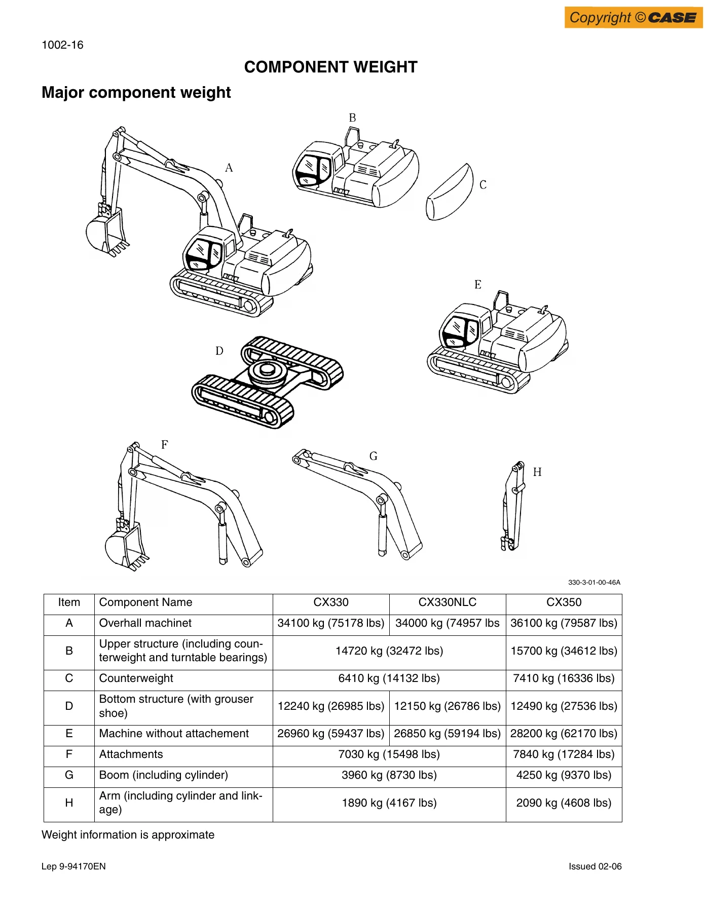
- Fluid Capacities: Fuel tank capacity of 580 L, engine crankcase lubricant 38 L, cooling system 30 L, hydraulic oil system 350 L (reservoir capacity 175 L), travel reduction gear 9.5 L per side, and swing reduction gear 6 L.
Tier 3 Common Rail Electronics & Diagnostic Monitor Systems
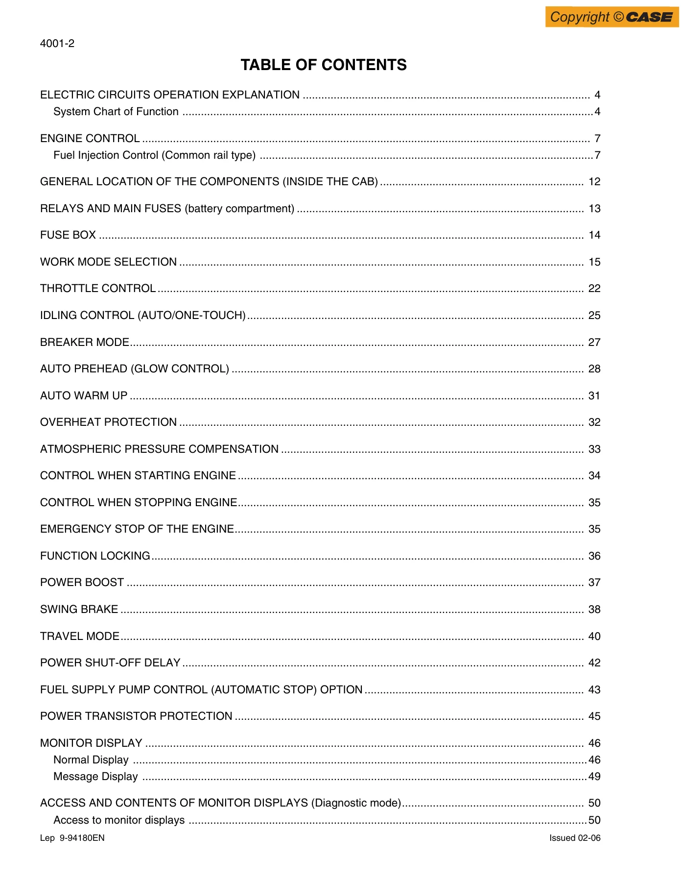
Troubleshooting complex electrical and electronic faults is streamlined with detailed instructions in Section 4001. The manual breaks down the 121-pin Tier 3 engine control module (ECM), CAN bus communication lines, sensor pinouts, and instrument cluster interfaces:
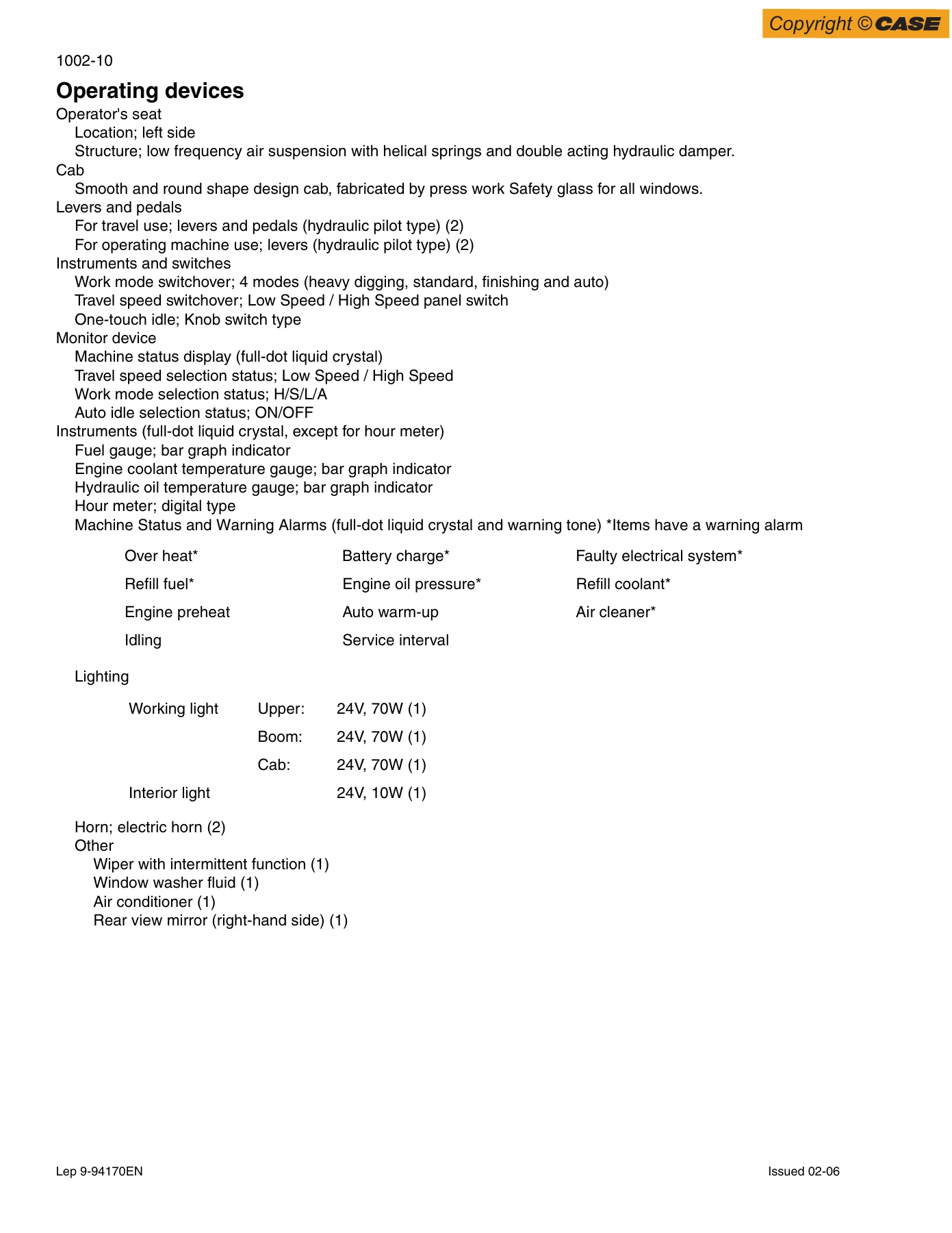
- Operational Logic: Full explanation of H (Super Heavy), S (Standard), L (Finishing), and Auto work modes, pump proportional solenoid current regulation (up to 470 mA), load pre-fetch control, auto-idle/one-touch idle transitions, auto preheat glow plug maps, and auto warm-up cycles.
- On-Board Diagnostic Modes: Detailed technician steps for accessing machine monitor menus: CHK1 through CHK6 for live sensor readings, voltage checks, and short-circuit auto-detection; DIAG1 through DIAG6 for active and logged failure codes; HR1 through HR12 for machine operating history and pressure distribution logs; and RST1/RST2 for auto-idle timing, breaker engine speed programming, and injector shutoff testing.
- Diagnostic Error Code Lists: Comprehensive breakdown of engine trouble codes (including fuel rail pressure faults 0087/0088/0089, SCV driver faults 0090/0092, boost and atmospheric sensors 0107/0108/0237/0238, temperature sensors 0112/0117/0182, injection circuits 0201–0206, and CAN timeout 2106) alongside machine chassis trouble codes M0010 through M00C0.
- Controller Setup: Step-by-step procedures for excavator model selection (setting code SH0300-4 for CX330), regional destination coding, language programming (codes 0 to 14), and controller re-initialization.
Undercarriage Overhaul, Track Chains & Planetary Final Drives
Maintain structural stability and driveline integrity using the mechanical rebuild guidelines provided in Divisions 5 and 6 of this Case CX330, CX330NLC and CX350 Tier 3 Crawler Excavator Service Manual:
- Track Chains & Tensioners: Disconnection and assembly procedures using portable track press CAS 10044, master pin installation, track shoe bolt torquing to 1236–1510 Nm, track sag adjustment (340 to 460 mm clearance), and grease tensioner cylinder repacking with wiper and O-ring replacements.
- Rollers & Idlers: Full disassembly of single/double flanged lower rollers, carrier upper rollers, and front idlers. Covers duo-cone floating seal replacement, bushing replacement via hydraulic press, and pneumatic leak test procedures using CAS 1450 and CAS 1682 at 1.9 bar test pressures.
- Drive Train Planetary Gears: Complete teardown and reassembly sequences for both the travel final drive and swing reduction units. Includes carrier pin removal, needle bearing installation, sun and planet gear backlash verification, floating seal seating with Loctite 515, and angular bearing pre-load shim calculations.
- Pin & Bushing Wear Standards: Wear limit charts and tolerance tables covering the boom foot (110 mm pin), boom cylinder head/rod eyes, arm cylinder, and bucket linkage connecting pins and shims.
Professional Workshop Utility & Instant Delivery
The Case CX330, CX330NLC and CX350 Tier 3 Crawler Excavator Service Manual – 9-94900EN delivers the technical rigor and practical step-by-step instructions needed to complete routine servicing, complex electronic fault tracing, and full mechanical rebuilds with complete confidence. Maintaining correct hydraulic relief settings, adhering to factory torque sequences with specified thread lockers, and following exact pin-and-bushing clearance tolerances prevents premature equipment downtime and costly component failures. Delivered as an instant digital PDF download immediately upon purchase, this manual is completely free of shipping delays, fully printable, and accessible on any laptop, tablet, or mobile device in the shop or on the job site.

Reviews
There are no reviews yet.