Case CX40B CX50B Hydraulic Excavator Shop Manual PDF Download
$44.95 Original price was: $44.95.$27.95Current price is: $27.95.
Complete Case CX40B and CX50B Hydraulic Excavator Shop Manual (No. 9-91940 GB) covering specifications, hydraulic and electrical systems, disassembly, troubleshooting, and full Yanmar 4TNV88-XYB engine overhaul procedures. Instant PDF download.
Description
Case CX40B CX50B Hydraulic Excavator Shop Manual
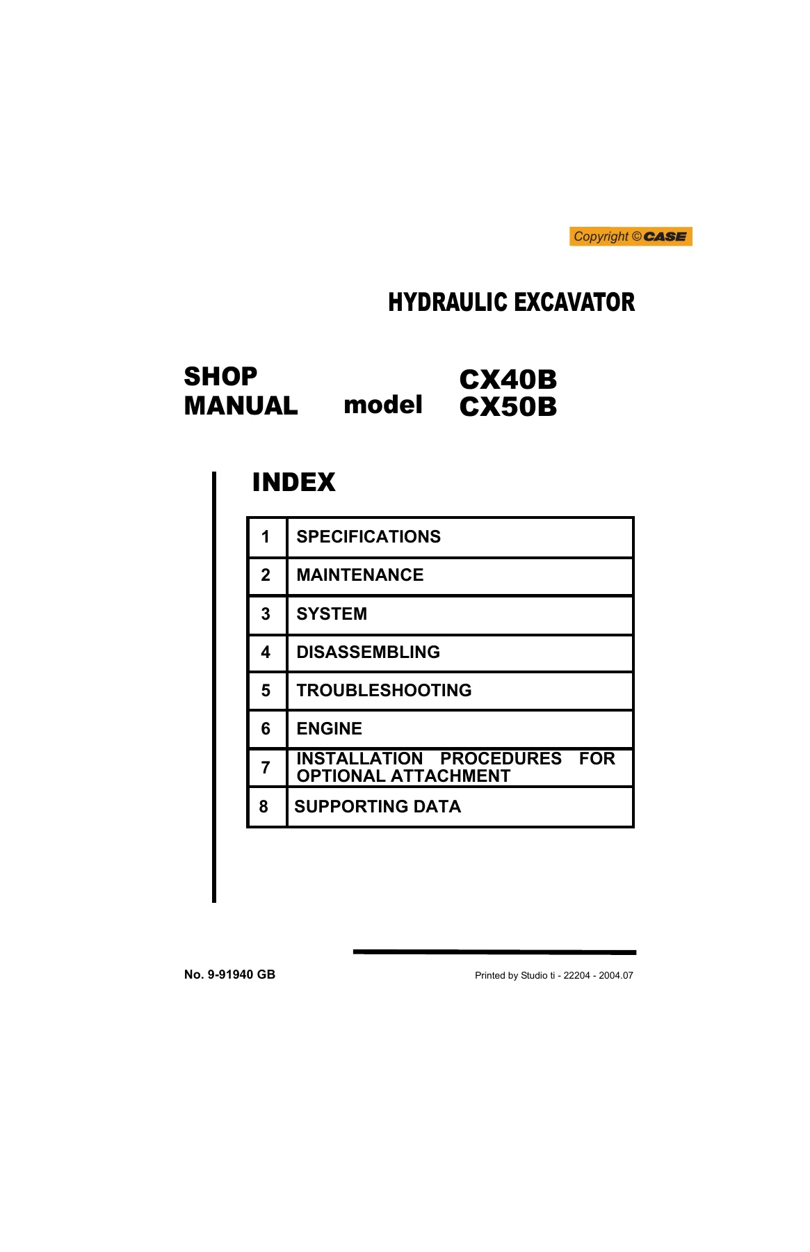
This Case CX40B CX50B Hydraulic Excavator Shop Manual (document No. 9-91940 GB) is the factory-style workshop reference built specifically for the CX40B and CX50B compact excavator platform. It is the same shop manual a dealer technician would reach for when specifications, torque values, or a full teardown procedure are needed, and it is delivered as an instant PDF rather than a bound book.
File Details
- Manual type: Shop Manual (workshop/service/repair manual)
- Brand / Models: Case CX40B and CX50B Hydraulic Excavators
- Applicable machines: CX40B PH05-03501~, CX50B PJ04-03001~
- Document number: 9-91940 GB
- Print reference: Studio ti – 22204 – 2004.07
- Language: English
- File format: PDF
Complete Bookmarks
The complete bookmarks in the βCase CX40B CX50B Hydraulic Excavator Shop Manual PDF Downloadβ are as follows:
+24.1 HYDRAULIC COMPONENTSp. 155
+24.2 ELECTRICAL EQUIPMENTp. 222
+CX40-50_2.pdf
+34.1.11 SLEWING BEARING 34-40p. 419
+34. TRAVEL SYSTEMp. 421
+34.1 REMOVING AND INSTALLINGp. 423
+Fig. 34-1 Name and location of partsp. 423
+9. Slewing bearingp. 423
+34.1.2 CRAWLERp. 423
+34.1.2.1 REMOVAL AND INSTALLATION PROCEDURESp. 423
+Fig. 34-4 Removing rubber crawlerp. 424
+Fig. 34-7 Crawler tensionp. 424
+Fig. 34-18 Extension of track link (Example for rubber crawler)p. 427
+Fig. 34-20 Construction of steel crawlerp. 428
+Fig. 34-21 Rubber crawler shoep. 429
+34.1.3 UPPER ROLLERp. 432
+34.1.3.1 REMOVAL AND INSTALLATION PROCEDURESp. 432
+Fig. 34-23 Supporting with wooden blocksp. 432
+Fig. 34-24 Removing/Installing upper rollerp. 433
+Fig. 34-25 Construction of upper rollerp. 433
+34.1.3.3 DISASSEMBLY AND ASSEMBLYp. 434
+Fig. 34-29 Extruding bushingp. 435
+Fig. 34-33 Filling oilp. 436
+Fig. 34-34 Sectional view of upper rollerp. 437
+34.1.5 TOOLS AND JIGSp. 438
+34.1.6 LOWER ROLLERp. 439
+34.1.6.1 REMOVAL AND INSTALLATION PROCEDURESp. 439
+Fig. 34-36 Crawler removing posturep. 439
+Fig. 34-37 Installing lower rollerp. 439
+Fig. 34-38 Lower roller constructionp. 440
+34.1.6.3 DISASSEMBLY AND ASSEMBLYp. 440
+Fig. 34-43 Removing bush (5)p. 441
+Fig. 34-48 Installing oil supply plug (9)p. 444
+Fig. 34-50 Lower rollerp. 445
+34.1.7 FRONT IDLERp. 447
+34.1.7.1 REMOVAL AND INSTALLATION PROCEDURESp. 447
+Fig. 34-52 Disassembling idler assemblyp. 447
+Fig. 34-53 Installing idler assemblyp. 447
+Fig. 34-54 Idler assembly constructionp. 448
+34.1.7.3 DISASSEMBLY AND ASSEMBLYp. 448
+Fig. 34-57 Removing bushingp. 449
+Fig. 34-62 Driving pin (5)p. 450
+Fig. 34-52 Idler assemblyp. 451
+34.1.8 IDLER ADJUSTERp. 453
+34.1.8.1 REMOVAL AND INSTALLATION PROCEDURESp. 453
+Fig. 34-53 Disassembling idler assemblyp. 453
+Fig. 34-72 Attach idler adjuster assembly to the jigp. 455
+Fig. 34-73 Idler adjuster assemblyp. 456
+34.1.9 SPROCKETp. 457
+34.1.9.1 REMOVAL AND INSTALLATION PROCEDURESp. 457
+Fig. 34-74 Making sprocket freep. 457
+Fig. 34-76 Tightening capscrewp. 457
+Fig. 34-77 Sprocketp. 457
+34.1.10 TRAVEL MOTORp. 458
+34.1.10.1 REMOVAL AND INSTALLATION PROCEDURESp. 458
+Fig. 34-80 Removing and installing travel motorp. 458
+49.0 (36)p. 459
+Fig. 34-83 Checking oil levelp. 459
+34.1.11 SLEWING BEARINGp. 460
+34.1.11.1 REMOVAL AND INSTALLATION PROCEDURESp. 460
+Fig. 34-85 Lifting slewing bearingp. 460
+Fig. 34-86 Location of "S" mark to install slewing bearingp. 460
+34.1.11.3 DISASSEMBLY AND ASSEMBLYp. 461
+Fig. 34-88 Disassembling slewing bearingp. 461
+Fig. 34-91 Installing spacerp. 462
+34.2 DISASSEMBLING AND ASSEMBLINGp. 463
+34.2.1 TRAVEL MOTORp. 463
+LS. Low speedp. 464
+M12p. 469
+34.2.1.3 DISASSEMBLYp. 470
+Fig. 34-151 Finish cleaningp. 486
+34.2.1.4 ASSEMBLYp. 487
+Fig. 34-186 Tightening plug (224)p. 496
+Fig. 34-196 Removing travel motorp. 499
+34.2.1.6 Performance verification testp. 502
+42.1.1 CONFIRM ACTUAL TROUBLED CONDITIONS AT SITE 42-3p. 503
+42. TROUBLESHOOTING (HYDRAULIC SYSTEM)p. 505
+42.1 GENERAL PRECAUTIONSp. 507
+Fig. 42-3 Diagnosing trouble by means troubleshooting.p. 507
+42.3 TROUBLESHOOTINGp. 509
+42.3.1 Attachmentp. 509
+42.3.2 Travel operationp. 511
+42.3.3 Slewing operationp. 514
+42.3.4 Pumpp. 515
+42.3.4.2 Malfunction of pumpp. 516
+43. TROUBLESHOOTING (ELECTRICAL SYSTEM)p. 519
+43.2 TROUBLESHOOTINGp. 522
+43.2.1 GENERALp. 522
+43.2.2 Attachment operationp. 526
+43.2.3 Travel operationp. 527
+43.2.4 Decelerationp. 528
+43.2.4.1 Decel change operation in option can not be carried out.p. 528
+44.2.4 OTHER TROUBLE 44-10p. 529
+44. TROUBLESHOOTING (ENGINE)p. 531
+44.2 TROUBLESHOOTINGp. 536
+44.2.1 STARTING TROUBLEp. 536
+NOTE: Check with the engine start key being in ON position.p. 537
+NOTE: Check the above items in the condition of coolant temperature at more than 50ΛC. (122ΛF)p. 538
+44.2.3 OUTPUT DROPS DOWNp. 539
+NOTE: Check in the condition of operating at high speed.p. 539
+NOTE: Check in the condition at engine coolant temperature of more than 50ΛC. (122ΛF)p. 540
+44.2.4 OTHER TROUBLEp. 540
+Costruction of breather mechanismp. 541
+NOTE: Check in the condition of no engine oil leakage.p. 542
+NOTE: Check in the condition the proper fuel is used.p. 542
+44.3 ELECTRICAL EQUIPMENTp. 543
+44.3.1 ELECTRICAL EQUIPMENT LISTp. 543
+71.1.3 SCHEMATIC PIPING FOR HYDRAULIC SYSTEM 71-13p. 761
+MIR CX40B -50B_A3_gb.pdf
+This page is blank because of editing convenience.
+71.2 ELECTRIC CIRCUIT DIAGRAM
+MIR CX40B -50B_A3_gb.pdf
+This page is blank because of editing convenience.
+71.2 ELECTRIC CIRCUIT DIAGRAM
+0051_MOTORE.pdf
Chapters Covered
- 1. Outline β general repair precautions, disassembly/assembly safety, SI unit conversion
- 2. Specifications β machine dimensions, performance data, engine specifications, weights
- 3. Attachment Dimensions β boom, arm, bucket and dozer dimensional data
- 11. Tools β special service tools and classification
- 12. Standard Maintenance Time Table β standard working time reference for maintenance jobs
- 13. Maintenance Standards and Test Procedures
- 22. Hydraulic System β circuit description and component function
- 23. Electrical System β wiring, connectors and component ratings
- 24. Components System β hydraulic pump, motors, control valve and cylinder specifications
- 31β34. Disassembling β whole machine, attachments, upper slewing structure and travel system disassembly/assembly
- 42β44. Troubleshooting β hydraulic system, electrical system and engine diagnostics
- 51. Engine β full Yanmar 4TNV88-XYB overhaul, inspection limits and reassembly
- Installation Procedures for Optional Attachment
- 71. Supporting Data β wiring and hydraulic circuit reference diagrams
Taken together, these chapters give a technician everything needed to work on a CX40B or CX50B from routine servicing through to a complete engine and hydraulic system rebuild, without having to guess at torque values, clearances or wiring color codes.
IMAGES PREVIEW
Engine and Hydraulic Coverage
The engine section is built around the Yanmar 4TNV88-XYB, a water-cooled, 4-cycle, swirl-chamber diesel with 4 cylinders, an 88 mm bore and 90 mm stroke, 2.189 L total displacement, and a rated output of 30.4 kW (41.3 PS) at 2400 min-1. Crankshaft, cylinder head, piston, ring and cylinder block inspection limits are all laid out with numeric tolerances, so a rebuild can be measured and verified rather than estimated. The hydraulic section documents the variable-displacement axial piston pump plus gear pump combination, the 11-spool multiple control valve, the travel motors with reducer, the swing motor, and the double-acting boom, arm, bucket, swing and dozer cylinders, with rated pressures and flow rates given for each component so a hydraulic fault can be traced to the correct part rather than swapped by trial and error.
Why This Case CX40B CX50B Shop Manual Matters
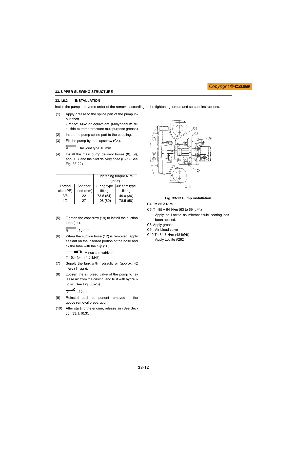
With this Case CX40B CX50B Hydraulic Excavator Shop Manual on hand, a technician can service, diagnose and repair either machine using the manufacturer’s own torque specifications, clearance limits and system pressures instead of generic figures pulled from a different model. Following the correct procedures for the hydraulic, electrical and engine systems protects the machine from the kind of damage that comes from improvised repairs, and keeps the excavator working to its designed performance and gradeability.
This Case CX40B CX50B Shop Manual is delivered as an instant PDF download immediately after payment β no shipping wait, no physical copy to lose. It can be opened on a laptop, tablet or phone in the shop, and printed if a paper copy is preferred for the bench.

What Our Customers Say
π Related Products
Discover more professional manuals for your equipment

New Holland LM1340 LM1343 LM1345 LM1443 LM1445 LM1745 Turbo Telehandler Workshop Manual PDF

Liebherr R920 Crawler Excavator Operator's Manual - From S/N 40104

Bitelli BB 681 CI Paver Finisher Spare Parts Book PDF (DR-259A010105A5, 2001)


Reviews
There are no reviews yet.