CAT Conveyor System BC200 48″ AFDD 150 HP 48″ HYDRAULIC TAKE UP 48″ REMOTE A-FRAME Parts & Operations Manual BI380942 – PDF DOWNLOAD
$28.94
CAT Conveyor System BC200 48″ AFDD 150 HP 48″ HYDRAULIC TAKE UP 48″ REMOTE A-FRAME Parts & Operations Manual BI380942 – PDF DOWNLOAD
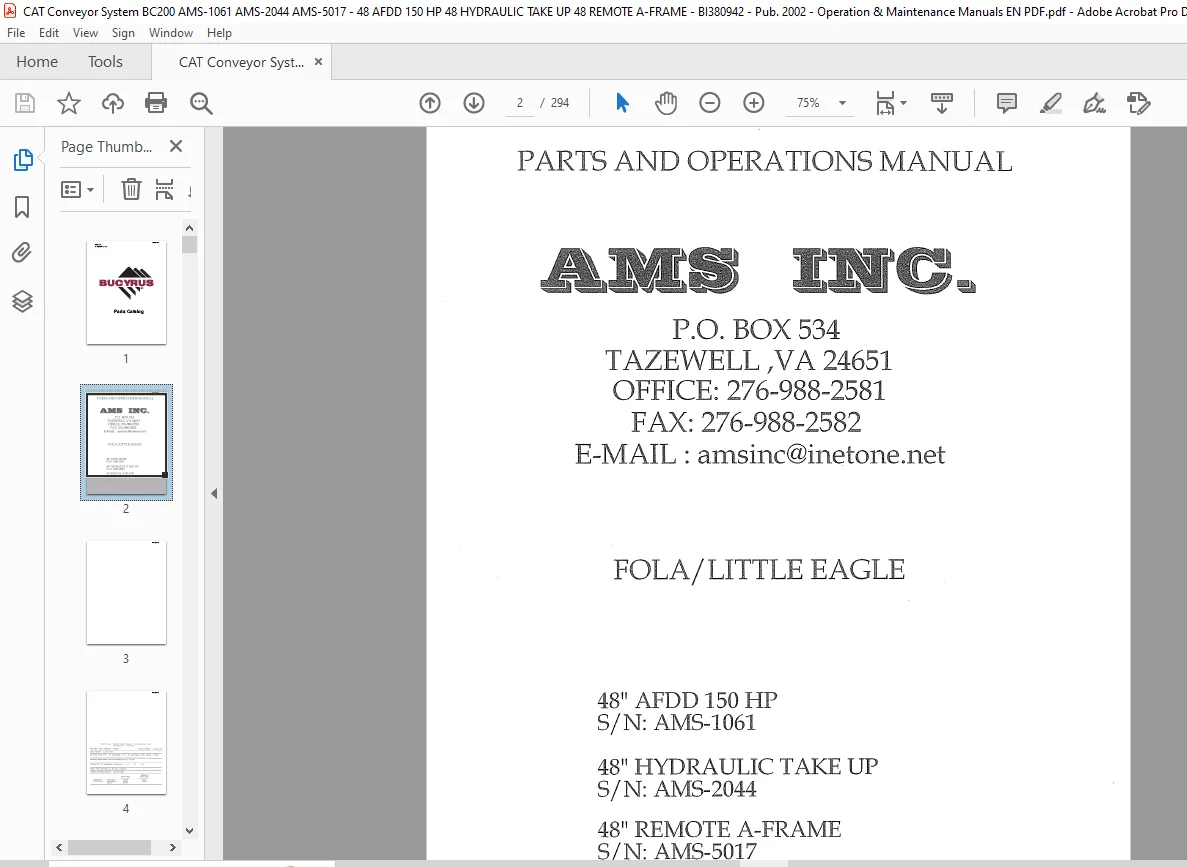
FOLA/LITTLE EAGLE
48″ AFDD 150 HP
S/N:AMS-1061
48″ HYDRAULIC TAKE UP
S/N:AMS-2044
48″ REMOTE A-FRAME
S/N:AMS-5017
Description
CAT Conveyor System BC200 48″ AFDD 150 HP 48″ HYDRAULIC TAKE UP 48″ REMOTE A-FRAME Parts & Operations Manual BI380942 – PDF DOWNLOAD
FILE DETAILS:
CAT Conveyor System BC200 48″ AFDD 150 HP 48″ HYDRAULIC TAKE UP 48″ REMOTE A-FRAME Parts & Operations Manual BI380942 – PDF DOWNLOAD
Language : English
Pages : 294
Downloadable : Yes
File Type : PDF
FOLA/LITTLE EAGLE
48″ AFDD 150 HP
S/N:AMS-1061
48″ HYDRAULIC TAKE UP
S/N:AMS-2044
48″ REMOTE A-FRAME
S/N:AMS-5017
IMAGES PREVIEW OF THE MANUAL:
DESCRIPTION:
CAT Conveyor System BC200 48″ AFDD 150 HP 48″ HYDRAULIC TAKE UP 48″ REMOTE A-FRAME Parts & Operations Manual BI380942 – PDF DOWNLOAD
General
L-B Driver Speed Reducers were designed for a variety of applications ranging from the m1rnng industry to material handling. Standard features include flippable housing arrangement, grease purgeable seal arrangement with split seal replacement capability, split fan design and many others.
This manual is written to help the users of L B Driver reducer’s install, operate and maintain this equipment with the same care given to it in the factory. Should questions arise that are not answered in this manual, please contact Geared Products Division Office listed on the back cover of this manual.
All speed reducers are factory tested. Internal parts are coated with rust preventive run-in oil before shipment. Seals are grease lubricated. Shaft projections and hollow shaft bores are coated with protective coating. Speed reducers are shipped from the factory without lubricating oil.
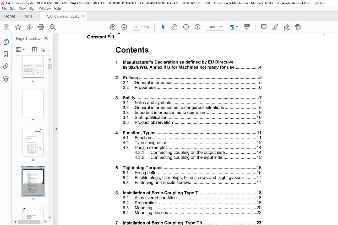
TABLE OF CONTENTS:
CAT Conveyor System BC200 48″ AFDD 150 HP 48″ HYDRAULIC TAKE UP 48″ REMOTE A-FRAME Parts & Operations Manual BI380942 – PDF DOWNLOAD
1 Manufacturer’s Declaration as defined by EU Directive
89/392/EWG, Annex II B for Machines not ready for use ………………. .4
2 Preface ………………………………………………………………………………………. 5
2.1 General information …………………………………………………………….. 5
2.2 Proper use …………………………………………………………………………. 6
3 Safety …………………………………………………………………………………………. 7
3.1 Notes and symbols ……………………………………………………………… 7
3.2 General information as to dangerous situations ………………………. 8
3.3 Important information as to operation …………………………………….. 9
3.4 Staff qualification ……………………………………………………………….. 10
3.5 Product observation …………………………………………………………… 10
4 Function, Types ………………………………………………………………………… 11
4.1 Function …………………………………………………………………………… 11
4.2 Type designation ……………………………………………………………….. 12
4.3 Design examples ………………………………………………………………. 14
4.3.1 Connecting coupling on the output side ……………………. 14
4.3.2 Connecting coupling on the input side ………………………. 15
5 Tightening Torques ………………………………………………………………….. 16
5.1 Fixing bolts ……………………………………………………………………….. 16
5.2 Fusible plugs, filler plugs, blind screws and sight glasses ………. 17
5.3 Fastening and nozzle screws ………………………………………………. 17
6 Installation of Basic Coupling Type T ………………………………………… 18
6.1 As delivered condition ………………………………………………………… 18
6.2 Preparation ………………………………………………………………………. 18
6.3 Mounting ………………………………………………………………………….. 20
6.4 Mounting devices ………………………………………………………………. 22
7 Installation of Basic Coupling Type TN …………………………………….. 23
7 .1 As delivered condition ………………………………………………………… 23
How to mount the coupling …………………………………………………………… 24
8 Alignment …………………………………………………………………………………. 25
8.1 Flexible connecting couplings ……………………………………………… 25
8.1.1 Connecting coupling on the input side ………………………. 25
8.1.2 Connecting coupling on the output side ……………………. 26
8.2 Laid lengths and type allocations turbo coupling / flexible
connecting coupling …………………………………………………………… 27
8.3 Alignment tolerances …………………………………………………………. 27
8.4 Alignment …………………………………………………………………………. 28
9 Operating Fluids ……………………………………………………………………….. 30
9.1 Requirements to be fulfilled by the operating fluid ………………….. 30
9.2 Proposed operating fluids …………………………………………………… 31
9.3 Proposed operating fluids for special requirements ………………… 32
10 Fill, Filling Check and Draining ………………………………………………….. 33
10.1 Coupling fill ………………………………………………………………………. 34
10.1.1 How to fill couplings installed in horizontal position …….. 34
10.1.2 How to fill couplings installed in vertical position ………… 35
10.2 Level check ………………………………………………………………………. 35
10.2.1 Level check
for couplings installed in horizontal position ………………. 35
10.2.2 Level check
for couplings installed in vertical position ………………….. 36
Contact us: [email protected]
https://vimeo.com/888147746?share=copy
S.S