

Cat Electric Rope Shovel Medium Voltage Controllers Bulletin 1512B USER MANUAL – PDF DOWNLOAD
Original price was: $79.00.$24.95Current price is: $24.95.
CAT Electric Rope Shovel 7295 495HD 295HR 141329 141484 – Medium Voltage Controller Bulletin 1512B – BI619879 – Pub. 2008 – 1500-UM055E-EN-P-EXT Operation & Maintenance Manuals EN PDF
Description
Cat Electric Rope Shovel Medium Voltage Controllers Bulletin 1512B USER MANUAL – PDF DOWNLOAD
DESCRIPTION:
Cat Electric Rope Shovel Medium Voltage Controllers Bulletin 1512B USER MANUAL – PDF DOWNLOAD
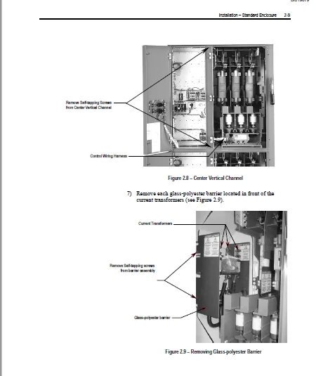
Important User Information
- Solid-state equipment has operational characteristics differing from those of electromechanical equipment. Safety Guidelines for the Application, Installation and Maintenance of Solid-State Controls wired electromechanical devices.
- Because of this difference, and also because of the wide variety of uses for solid-state equipment, all persons responsible for applying this equipment must satisfy themselves that each intended application of this equipment is acceptable. In no event will Rockwell Automation, Inc.
- be responsible or liable for any indirect or consequential damages resulting from the use or application of this equipment. The examples and diagrams in this manual are included solely for illustrative purposes. Because of the many variables and requirements associated with any particular installation, Rockwell Automation, Inc. cannot assume responsibility or liability for actual use, based on the examples and diagrams.
- No patent liability is assumed by Rockwell Automation, Inc. with respect to use of information, circuits, equipment, or software described in this manual. Reproduction of the contents of this manual, in whole or in part, without written permission of Rockwell Automation, Inc. is prohibited. Throughout this manual, when necessary we use notes to make you aware of safety considerations.
WARNING : Identifies information about practices or circumstances that can cause an explosion in a hazardous environment, which may lead to personal injury or death, property damage, or economic loss.
IMPORTANT : Identifies information that is critical for successful application and understanding of the product.
ATTENTION : Identifies information about practices or circumstances that can lead to personal injury or death, property damage, or economic loss. Attentions help you identify a hazard, avoid a hazard, and recognize the consequences.
SHOCKHAZARD :Labels may be on or inside the equipment (for example, drive or motor) to alert people that dangerous voltage may be present.
BURNHAZARD :Labels may be on or inside the equipment (for example, drive or motor) to alert people that surfaces may reach dangerous temperatures.
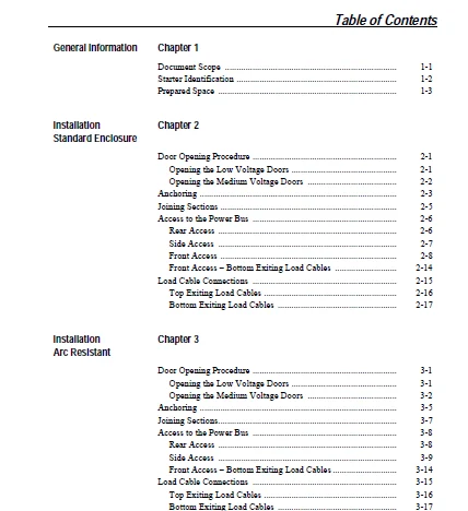
TABLE OF CONTENTS:
Cat Electric Rope Shovel Medium Voltage Controllers Bulletin 1512B USER MANUAL – PDF DOWNLOAD
Front Cover........................................................................  1
1512B_Inside Front Cover...........................................................  2
TOC................................................................................  3
Chapter 1 - GENERAL INFORMATION
...................................................  7
	Document Scope
................................................................  7
	Starter Identification
........................................................  8
	Prepared Space
................................................................  9
	Recommended Torque Values
.....................................................  9
Chapter 2- INSTALLATION - STANDARD ENCLOSURE
...................................... 11
	Door Opening Procedure
........................................................ 11
		Opening the Low Voltage Doors
............................................. 11
		Opening the Medium Voltage Doors
.......................................... 12
		Anchoring
................................................................. 13
		Joining Sections
.......................................................... 15
		Access to the Power Bus
................................................... 16
			Rear Access
........................................................... 16
			Side Access
........................................................... 17
			Front Access
.......................................................... 18
			Front Access- Bottom Exiting Load Cables
............................. 24
		Load Cable Connections
.................................................... 25
			Top Exiting Load Cables
............................................... 26
			Bottom Exiting Load Cables
............................................ 27
Chapter 3 - INSTALLATION - ARC-RESISTANT ENCLOSURE (ARCSHIELD)..................... 29
	Door Opening Procedure
........................................................ 29
		Opening the Low Voltage Doors
............................................. 29
		Opening the Medium Voltage Doors
.......................................... 30
	Anchoring
..................................................................... 32
	Joining Sections
 ............................................................. 34
	Access to the Power Bus
....................................................... 35
		Rear Access
............................................................... 35
		Side Access
............................................................... 36
		Front Access
.............................................................. 37
		Front Access - Bottom Exiting Load Cables
................................. 41
	Load Cable Connections
........................................................ 42
		Top Exiting Load Cables
................................................... 43
		Bottom Exiting Load Cables
................................................ 44
Chapter 4 - COMMON INSTALLATION
................................................... 45
	Bus Splicing
.................................................................. 45
		Power Bus
................................................................. 45
		Insulated Power Bus Splicing
.............................................. 47
		Ground Bus
................................................................ 47
	Incoming Line Cable Connections
............................................... 48
	Installation of Current Transformer Barrier
................................... 49
	Hi-Pot and Megger Test
........................................................ 50
	Start-Up Procedure
............................................................ 50
		Contactor Inspection
...................................................... 50
		Preliminary Checks
........................................................ 51
		Testing Contactor Operation
 .............................................. 51
Chapter 5 - MAINTENANCE
........................................................... 55
	Tool Requirements
............................................................. 55
	Recommended Torque Values
..................................................... 56
	Door Interlock Circumvention
.................................................. 56
	Power Lock-out Procedure
...................................................... 57
	Fuse Removal and Replacement
.................................................. 60
		Bolt-On Fuse removal/installation
......................................... 62
		Clip-on Fuse removal/ installation
....................................... 62
		Contactor Maintenance
..................................................... 64
		Removing the Contactor
.................................................... 64
		Contactor Interlock Rod Adjustment
........................................ 66
			To Reduce the Gap Distance
............................................ 67
			To Increase the Gap Distance
.......................................... 67
		Isolatoin Switch Mechanism Inspection and Lubrication
..................... 68
		Isolation Switch Mechanism Grounding Adjustment
........................... 71
		Auxiliary Contacts Inspection and Replacement
............................. 72
		Isolation Switch Auxiliary Contacts
....................................... 73
			Adjusting the Normally Open (ISa)
 .................................... 74
			Adjusting the Normally Closed (ISb).................................... 75
			Adjusting the Change-of-State Point
................................... 75
		Emergency Circumvention Procedure for Power Cell Entry
.................... 76
			Installing Z-clip with Isolation Switch Handle in the OFF Position
.... 78
			Installing Z-clip with Isolation Switch Handle in the ON Position
..... 78
Chapter 6 - SPARE PARTS
...........................................................  0
	Spare Parts List
..............................................................  0
Appendix A - ARCHIELD UNIT INFORMATION
............................................ 79
	Overview
...................................................................... 79
	ArcShield Design
.............................................................. 79
	Exhaust Systems: Chimney or Plenum Option
 .................................... 80
	Plenum Information
............................................................ 80
	Plenum Exhause Considerations
................................................. 81
	Additional Notes
.............................................................. 84
	Chimney Information
........................................................... 84
	Chimney Exhaust Considerations ................................................ 84
Appendix B - ARCSHIELD PLENUM INSTALLATION INSTRUCTIONS
........................... 85
	Recommended Torque Values
..................................................... 85
	Plenum Bracing
................................................................ 85
	General Plenum Layout for ArcShield Line-up
................................... 88
		Step 1 - Mounting a Single Plenum
......................................... 89
			Cabinet Preparation
................................................... 89
			Plenum Placement on Structure
......................................... 90
		Step 2 - Alignment of "Side-by-Side" Plenums
.............................. 91
		Step 3 - Sequence of Final Assembly
....................................... 92
		Step 4 - Closing the Front of the Plenum Sections
......................... 93
		Step 5 - Extension and Elbow Assembly
..................................... 94
		Step 6 - Mounting Extension/Elbow to Plenum "line-up"
..................... 95
		Step 7 - Additional Mounting Support
...................................... 96
Appendix C - ARCSHIELD CHIMNEY INSTALLATION INSTRUCTIONS
.......................... 97
	Recommended Torque Values
..................................................... 97
	General Plenum Layout for ArcShield Line-up
................................... 98
		Cabinet Preparation
....................................................... 99
		Chimney Placement on Structure
............................................100
Blank Page.........................................................................  0
Back Cover.........................................................................101
CAT ELECTRIC ROPE SHOVEL MEDIUM VOLTAGE CONTROLLERS BULLETIN 1512B USER MANUAL – PDF DOWNLOAD:
IMAGES PREVIEW OF THE MANUAL:


PLEASE NOTE:
- This is not a physical manual but a digital manual – meaning no physical copy will be couriered to you. The manual can be yours in the next 2 mins as once you make the payment, you will be directed to the download page IMMEDIATELY.
- This is the same manual used by the dealers inorder to diagnose your vehicle of its faults.
- Require some other service manual or have any queries: please WRITE to us at [email protected]
S.M