Trusted Business
Verified & Licensed
Virus Free Files
100% Safe Downloads
Secure Payment
SSL Protected
Instant Delivery
Available Immediately
Sale!


 Parts Manual - PDF Download")
CAT Telehandler TL1255 (TBN) Parts Manual – PDF Download  Parts Manual - PDF Download")
CAT Telehandler TL1255 (TBN) Parts Manual – PDF Download
CAT Telehandler TL1255 (TBN) Parts Manual – PDF Download
Original price was: $89.95.$39.95Current price is: $39.95.
CAT Telehandler TL1255 (TBN) Parts Manual – PDF Download
S/N TBM00100 & After
S/N TBN00100 & After
Instant PDF Download
Available immediately
Save to Your Device
Download & keep forever
Antivirus Scanned
100% virus-free
Trusted Worldwide
175,000+ customers
Description
CAT Telehandler TL1255 (TBN) Parts Manual – PDF Download
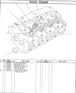
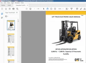
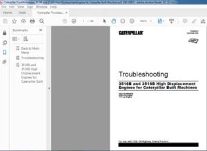
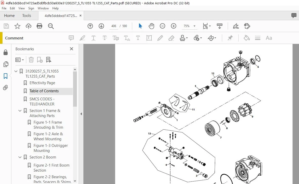
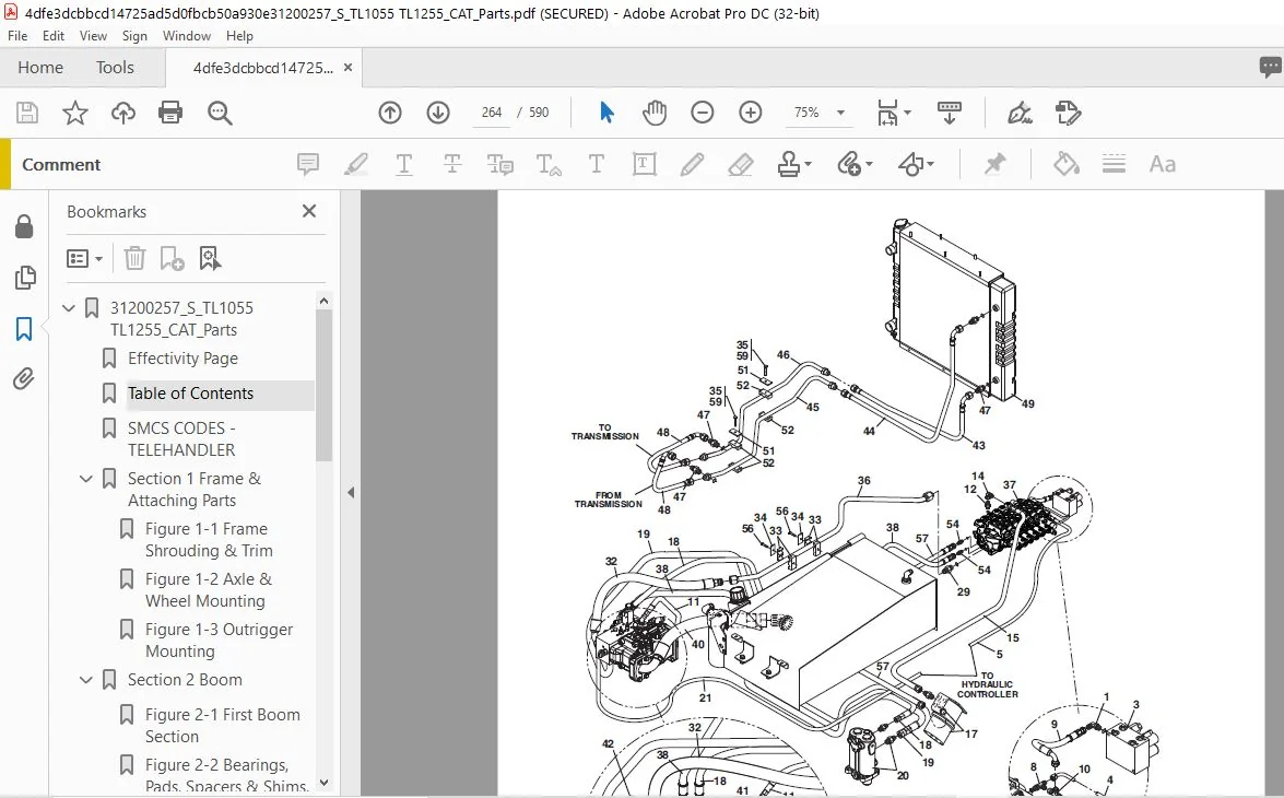
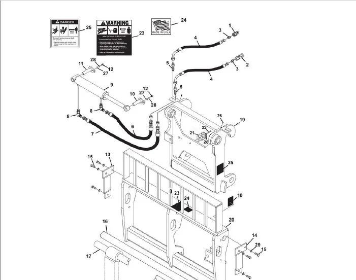
IMAGES PREVIEW OF THE MANUAL:
 Parts Manual - PDF Download")
 Parts Manual - PDF Download")
FILE DETAILS:
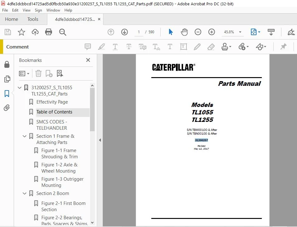
CAT Telehandler TL1255 (TBN) Parts Manual – PDF Download
Language : English
Pages : 590
Downloadable : Yes
File Type : PDF
Size: 51.4 MB
TABLE OF CONTENTS:
CAT Telehandler TL1255 (TBN) Parts Manual – PDF Download
31200257_S_TL1055 TL1255_CAT_Parts...........................................  1
	Effectivity Page.........................................................  3
	Table of Contents........................................................  5
	SMCS CODES - TELEHANDLER................................................. 11
	Section 1 Frame & Attaching Parts........................................ 17
		Figure 1-1 Frame Shrouding & Trim.................................... 18
		Figure 1-2 Axle & Wheel Mounting..................................... 26
		Figure 1-3 Outrigger Mounting........................................ 28
	Section 2 Boom........................................................... 31
		Figure 2-1 First Boom Section........................................ 32
		Figure 2-2 Bearings, Pads, Spacers & Shims, (First Boom Section)..... 36
		Figure 2-3 Second Boom Section....................................... 40
		Figure 2-4 Bearings, Pads, Spacers & Shims, (Second Boom Section).... 46
		Figure 2-5 Third Boom Section........................................ 50
		Figure 2-6 Bearings, Pads, Spacers & Shims, (Third Boom Section)..... 54
		Figure 2-7 Fourth Boom Section....................................... 58
		Figure 2-8 Bearings, Pads, Spacers & Shims, (Fourth Boom Section).... 62
		Figure 2-9 Quick Coupler Assembly.................................... 66
		Figure 2-10 Hydraulic Quick Coupler Assembly......................... 68
	Section 3 Attachments.................................................... 73
		Figure 3-1 Carriage Assembly......................................... 74
		Figure 3-2 Forks..................................................... 76
		Figure 3-3 Winch Installation........................................ 78
		Figure 3-4 Side Tilt Carriage Assembly............................... 80
		Figure 3-5 Fork Clamp Installation................................... 82
		Figure 3-6 Fork Mounted Platform..................................... 84
		Figure 3-7 Fork Mounted Hook......................................... 88
		Figure 3-8 Dual Fork Positioning Carriage............................ 90
		Figure 3-9 100 Degree Swing Carriage................................. 92
		Figure 3-10 180 Degree Swing Carriage................................ 94
		Figure 3-11 Side Shift Carriage...................................... 98
	Section 4 Engine & Attaching Parts.......................................101
		Figure 4-1 Engine Assembly...........................................102
		Figure 4-2 CAT Engine................................................112
		Figure 4-3 CAT Engine................................................116
		Figure 4-4 Fuel Tank & Lines.........................................118
		Figure 4-5 Radiator Assembly.........................................120
		Figure 4-6 Air Cleaner Installation..................................128
		Figure 4-7 Exhaust Installation......................................134
		Figure 4-8 ZF Transmission...........................................138
		Figure 4-9 ZF Transmission - Converter & Input.......................140
		Figure 4-10 ZF Transmission - Gearbox Housing........................142
		Figure 4-11 ZF Transmission - Forward Gear Group.....................144
		Figure 4-12 ZF Transmission - Reverse Gear Group.....................146
		Figure 4-13 ZF Transmission - 1st Shaft Group........................148
		Figure 4-14 ZF Transmission - 2nd Shaft Group........................150
		Figure 4-15 ZF Transmission - 3rd Shaft Group........................152
		Figure 4-16 ZF Transmission - 4th Shaft Group........................154
		Figure 4-17 ZF Transmission - Power Take-Off.........................156
		Figure 4-18 ZF Transmission - Control Unit & Pressure Regulator......158
		Figure 4-19 ZF Transmission - Gearshift System.......................160
		Figure 4-20 ZF Transmission - Oil Pump, Filter & Dipstick............162
		Figure 4-21 ZF Transmission - Transfer Box...........................164
	Section 5 Drive Train....................................................167
		Figure 5-1 Front Axle Assembly.......................................168
		Figure 5-2 Front Axle - Central Housing & Steering...................170
		Figure 5-3 Front Axle - Differential.................................172
		Figure 5-4 Front Axle - Hub Reduction................................174
		Figure 5-5 Front Axle - Brakes.......................................178
		Figure 5-6 Rear Axle Assembly........................................180
		Figure 5-7 Rear Axle - Central Housing & Steering....................182
		Figure 5-8 Rear Axle - Differential..................................184
		Figure 5-9 Rear Axle - Hub Reduction.................................186
		Figure 5-10 Rear Axle - Brakes.......................................190
		Figure 5-11 Drive Shaft..............................................194
		Figure 5-12 Tires & Rims.............................................196
	Section 6 Cab............................................................203
		Figure 6-1 Cab Assembly..............................................204
		Figure 6-2 Cab.......................................................212
		Figure 6-3 Suspension Seat...........................................220
		Figure 6-4 Instrument Panel..........................................222
		Figure 6-5 Heating Components........................................226
		Figure 6-6 Open Cab Heater Option....................................234
		Figure 6-7 Air Conditioning..........................................238
		Figure 6-8 Air Conditioning Components...............................246
	Section 7 Controls.......................................................251
		Figure 7-1 Boom Joystick with Adjustable Tilt........................252
		Figure 7-2 Hydraulic Controller - Outrigger & Sway/Aux...............254
		Figure 7-3 Steering Column & Attaching Parts.........................256
		Figure 7-4 Brake Pedal Assembly......................................258
		Figure 7-5 Accelerator Pedal.........................................260
	Section 8 Hydraulic Circuits.............................................263
		Figure 8-1 Supply Circuit............................................264
		Figure 8-2 Dump Circuit..............................................276
		Figure 8-3 Steer Select..............................................282
		Figure 8-4 Service/Park Brake........................................284
		Figure 8-5 Boom Joystick.............................................286
		Figure 8-6 Sway/Auxiliary Controller.................................288
		Figure 8-7 Outrigger Controller......................................294
		Figure 8-8 Lift Cylinder.............................................296
		Figure 8-9 Crowd Cylinder............................................300
		Figure 8-10 Tilt & Tilt Compensating Cylinders.......................304
		Figure 8-11 Auxiliary Function.......................................308
		Figure 8-12 Boom Hydraulics Assembly.................................316
		Figure 8-13 Sway Cylinder............................................318
		Figure 8-14 Outrigger Cylinders......................................324
	Section 9 Hydraulic Components...........................................331
		Figure 9-1 Lift Cylinder.............................................332
		Figure 9-2 Crowd Cylinder............................................346
		Figure 9-3 Tilt Cylinder.............................................352
		Figure 9-4 Compensating Cylinder.....................................364
		Figure 9-5 Sway Cylinder.............................................376
		Figure 9-6 Stabilizer Cylinder.......................................382
		Figure 9-7 Outrigger Cylinder Assembly...............................388
		Figure 9-8 Dual Fork Positioning Carriage Cylinder...................392
		Figure 9-9 Main Control Valve........................................394
		Figure 9-10 Hydraulic Pump...........................................400
		Figure 9-11 Variable Displacement Pump...............................406
		Figure 9-12 Hydraulic Tank Assembly..................................408
		Figure 9-13 Brake Valve..............................................414
		Figure 9-14 Hydraulic Manifold.......................................418
		Figure 9-15 Steer Select Valve.......................................420
		Figure 9-16 Quick Coupler Cylinder...................................422
		Figure 9-17 Decompression Valve......................................426
		Figure 9-18 Swing Carriage Cylinder..................................428
		Figure 9-19 180 Degree Swing Carriage Cylinder.......................430
		Figure 9-20 Side Shift Carriage Cylinder.............................432
		Figure 9-21 Side Tilt Carriage Cylinder..............................434
	Section 10 Electrical....................................................439
		Figure 10-1 Battery & Cables.........................................440
		Figure 10-2 Battery Disconnect Installation..........................448
		Figure 10-3 Engine Harness...........................................452
		Figure 10-4 Chassis Harness..........................................462
		Figure 10-5 Dash Harness.............................................472
		Figure 10-6 Transmission Harness.....................................476
		Figure 10-7 Transmission Relay Harness...............................480
		Figure 10-8 Enclosed Cab Harness.....................................484
		Figure 10-9 VEC Options Harness......................................486
		Figure 10-10 A/C Harness.............................................494
		Figure 10-11 Auxiliary Electrics.....................................496
		Figure 10-12 Cab Work Light Harness..................................498
	Section 11 Decals........................................................501
		Figure 11-1 Cab & Frame Decals.......................................502
		Figure 11-2 Boom Decals..............................................508
	Section 12 Options.......................................................511
		Figure 12-1 Work Light Package.......................................512
		Figure 12-2 Fender Installation......................................522
		Figure 12-3 Pintle Hook Installation.................................524
		Figure 12-4 Counterweight with Pintle Hitch..........................526
		Figure 12-5 8 IN Winch...............................................528
		Figure 12-6 Winch Motor..............................................532
		Figure 12-7 Pressure Reducer Valve...................................534
		Figure 12-8 Block Heater Installation................................536
		Figure 12-9 Boom Lights Installation.................................538
		Figure 12-10 Skylight Wiper Assembly.................................540
		Figure 12-11 Road Lights Installation................................542
		Figure 12-12 Top Cab Glass Shield....................................546
		Figure 12-13 Front Cab Glass Shield..................................548
		Figure 12-14 Cold Weather Package....................................550
		Figure 12-15 Arctic Package..........................................552
		Figure 12-16 Beacon Light Mount with AC..............................554
		Figure 12-17 Boom Work Light Harness.................................558
		Figure 12-18 Work Light Cab Harness..................................560
		Figure 12-19 Work Light Cab Harness..................................562
		Figure 12-20 Winch...................................................566
	Maintenance Parts List...................................................569
	Part Number Index........................................................573
CAT TELEHANDLER TL1255 (TBN) PARTS MANUAL – PDF DOWNLOAD:
PLEASE NOTE:
- This is the same manual used by the dealers to diagnose and troubleshoot your vehicle
- You will be directed to the download page as soon as the purchase is completed. The whole payment and downloading process will take anywhere between 2-5 minutes
- Need any other service / repair / parts manual, please feel free to contact [email protected] . We still have 50,000 manuals unlisted
S.V