CAT TH255 TH255C Telehandler Axle Service manual + Disassembly & Assembly Manual – PDF DOWNLOAD
Original price was: $70.00.$39.95Current price is: $39.95.
CAT TH255 TH255C Telehandler Axle Service manual + Disassembly & Assembly Manual – PDF DOWNLOAD
SN TBS00100 to Present
SN JK200150 to Present
SN JK300150 to Present
Description
CAT TH255 TH255C Telehandler Axle Service manual + Disassembly & Assembly Manual – PDF DOWNLOAD
DESCRIPTION:
CAT TH255 TH255C Telehandler Axle Service manual + Disassembly & Assembly Manual – PDF DOWNLOAD
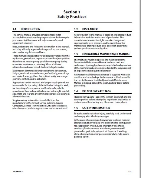
INTRODUCTION
- This service manual provides general directions for accomplishing service and repair procedures. Following the procedures in this manual will help assure safety and equipment reliability.
- Read, understand and follow the information in this manual, and obey all locally approved safety practices, procedures, rules, codes, regulations and laws.
- These instructions cannot cover all details or variations in the equipment, procedures, or processes described, nor provide directions for meeting every possible contingency during operation, maintenance, or testing. When additional information is desired consult the local Caterpillar dealer.
- Many factors contribute to unsafe conditions: carelessness, fatigue, overload, inattentiveness, unfamiliarity, even drugs and alcohol, among others. For optimal safety, encourage everyone to think, and to act safely.
- Appropriate service methods and proper repair procedures are essential for the safety of the individual doing the work, for the safety of the operator, and for the safe, reliable operation of the machine.
- All references to the right side, left side, front and rear are given from the operator seat looking in a forward direction.
- Supplementary information is available from the manufacturer in the form of Service Bulletins, Service Campaigns, Service Training Schools, the service website, other literature, and through updates to the manual itself.
DISCLAIMER
All information in this manual is based on the latest product information available at the time of publication. The manufacturer reserves the right to make changes and improvements to its products, and to discontinue the manufacture of any product, at its discretion at any time without public notice or obligation
OPERATION & MAINTENANCE MANUAL
The mechanic must not operate the machine until the Operation & Maintenance Manual has been read and understood, training has been accomplished and operation of the machine has been completed under the supervision of an experienced and qualified operator. An Operation & Maintenance Manual is supplied with each machine and must be kept in the manual holder located in the cab. In the event that the Operation & Maintenance Manual is missing, consult the local Caterpillar dealer before proceeding.
DO NOT OPERATE TAGS
Place Do Not Operate Tags on the ignition key switch and the steering wheel before attempting to perform any service or maintenance. Remove key and disconnect battery leads
SAFETY INFORMATION
To avoid possible death or injury, carefully read, understand and comply with all safety messages. In the event of an accident, know where to obtain medical assistance and how to use a first aid kit and fire extinguisher/ fire suppression system. Keep emergency telephone numbers (fire department, ambulance, rescue squad/ paramedics, police department, etc.) nearby. If working alone, check with another person routinely to help assure personal safety.
TABLE OF CONTENTS:
CAT TH255 TH255C Telehandler Axle Service manual + Disassembly & Assembly Manual – PDF DOWNLOAD
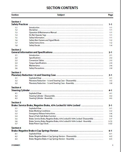
Section 1
Safety Practices 1-1
1 1 Introduction 1-1
1 2 Disclaimer 1-1
1 3 Operation & Maintenance Manual 1-1
1 4 Do Not Operate Tags 1-1
1 5 Safety Information 1-1
1 6 Safety Alert System and Signal Words 1-2
1 7 Safety Instructions 1-2
1 8 Safety Decals 1-4
Section 2
General Information and Specifications 2-1
2 1 Introduction 2-1
2 2 Specifications 2-2
2 3 Conversion Tables 2-3
2 4 Torque Specifications 2-4
2 5 Maintenance 2-6
2 6 Safety Precautions 2-9
Section 3
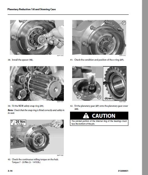
Planetary Reduction 1:6 and Steering Case 3-1
3 1 Exploded View 3-1
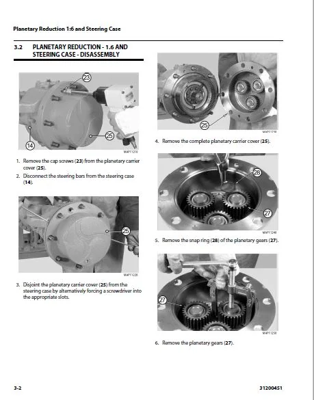
3 2 Planetary Reduction – 1 6 and Steering Case – Disassembly 3-2
3 3 Planetary Reduction – 1 6 and Steering Case – Assembly 3-8
Section 4
Steering Cylinder 4-1
4 1 Exploded View 4-1
4 2 Steering Cylinder – Disassembly 4-2
4 3 Steering Cylinder – Assembly 4-5
Section 5
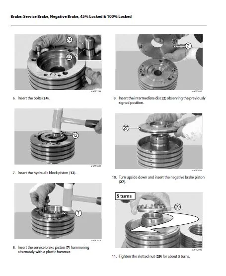
Brake: Service Brake, Negative Brake, 45% Locked & 100% Locked 5-1
5 1 Exploded View 5-1
5 2 Brake Working Conditions 5-2
5 3 Emergency Release Instructions 5-6
5 4 Reset of Fails Safe Brake Function 5-6
5 5 Brake: Service Brake, Negative Brake, 45% Locked & 100% Locked- Disassembly 5-7
5 6 Brake: Service Brake, Negative Brake, 45% Locked & 100% Locked – Assembly 5-13
5 7 Brake Piston Gap Check 5-22
Section 6
Brake: Negative Brake 4 Cup Springs Version 6-1
6 1 Exploded View 6-1
6 2 Brake: Negative Brake 4 Cup Springs Version – Disassembly 6-2
6 3 Brake: Negative Brake 4 Cup Springs Version – Assembly 6-3
Section Subject Page
ii 31200451
Section 7
Normal Preloaded Differential Unit (Old Version) 7-1
7 1 Exploded View 7-1
7 2 Normal Preloaded Differential Unit (Old Version) – Disassembly 7-2
7 3 Normal Preloaded Differential Unit (Old Version) – Assembly 7-6
Section 8
Normal Preloaded Differential Unit (Intermediate Version) 8-1
8 1 Exploded View 8-1
8 2 Normal Preloaded Differential Unit (Intermediate Version) – Disassembly 8-2
8 3 Normal Preloaded Differential Unit (Intermediate Version) – Assembly 8-6
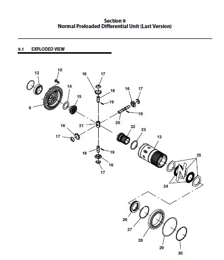
Section 9
Normal Preloaded Differential Unit (Last Version) 9-1
9 1 Exploded View 9-1
9 2 Normal Preloaded Differential Unit (Last Version) – Disassembly 9-2
9 3 Normal Preloaded Differential Unit (Last Version) – Assembly 9-5
Section 10
Flanged Reduction Gear 603 Type: Integral 603 Input Gear 10-1
10 1 Exploded View 10-1
10 2 Flanged Reduction Gear 603 Type: Integral 603 Input Gear – Disassembly 10-2
10 3 Flanged Reduction Gear 603 Type: Integral 603 Input Gear – Assembly 10-5
Section 11
Bevel Pinion: Normal Flange and Nut Revolution Counter Version 11-1
11 1 Exploded View 11-1
11 2 Bevel Pinion: Normal Flange and Nut Revolution Counter Version- Disassembly 11-2
11 3 Bevel Pinion: Normal Flange and Nut Revolution Counter Version – Assembly 11-5
Section 12
Ring and Pinion Adjusting: Step for Preloaded Differential 12-1
12 1 Exploded View 12-1
12 2 Ring and Pinion Adjusting: Step for Preloaded Differential – Install and Adjust 12-2
Section 13
Swinging Support 13-1
13 1 Exploded View 13-1
13 2 Swinging Support – Disassembly 13-2
13 3 Swinging Support – Assembly 13-4
Section 14
Planetary Reduction: 1:4, 23 14-1
14 1 Exploded View 14-1
14 2 Planetary Reduction: 1:4, 23 – Disassembly 14-2
14 3 Planetary Reduction: 1:4, 23 – Assembly 14-3
Section Subject Page
31200451 iii
Section 15
Brake: Incoming Disc Brake 15-1
15 1 Exploded View 15-1
15 2 Brake: Incoming Disc Brake – Disassembly 15-2
15 3 Brake: Incoming Disc Brake – Assembly 15-4
15 4 Checking Wear and Replacing the Braking Pads 15-6
Section 16
Brake: Service and Mechanical Parking Brake 16-1
16 1 Exploded View 16-1
16 2 Brake: Incoming Disc Brake – Disassembly 16-2
16 3 Brake: Incoming Disc Brake – Assembly 16-8
Section 17
Brake: Parking Brake and Differential Hydraulic 100% 17-1
17 1 Exploded View 17-1
17 2 Brake: Incoming Disc Brake- Disassembly 17-2
17 3 Brake: Incoming Disc Brake- Assembly 17-5
Section 18
Differential With Block to Spheres 100% (Old Version) 18-1
18 1 Exploded View 18-1
18 2 Differential With Block to Spheres 100% (Old Version) – Disassembly 18-2
18 3 Differential With Block to Spheres 100% (Old Version) – Assembly 18-7
Section 19
Differential With Block to Spheres 100% (Last Version) 19-1
19 1 Exploded View 19-1
19 2 Differential With Block to Spheres 100% (Last Version)- Disassembly 19-2
19 3 Differential With Block to Spheres 100% (Last Version)- Assembly 19-5
Section 20
Normal Differential (Old Version) 20-1
20 1 Exploded View 20-1
20 2 Normal Differential (Old Version) – Disassembly 20-2
20 3 Normal Differential (Old Version) – Assembly 20-5
Section 21
Normal Differential (Last Version) 21-1
21 1 Exploded View 21-1
21 2 Normal Differential (Last Version) – Disassembly 21-2
21 3 Normal Differential (Last Version) – Assembly 21-6
Section 22
Limited Slip Differential Unit 45% (Old Version) 22-1
22 1 Exploded View 22-1
22 2 Limited Slip Differential Unit 45% (Old Version) – Disassembly 22-2
22 3 Limited Slip Differential Unit 45% (Old Version) – Assembly 22-5
Limited Slip Differential Unit 45% (Last Version) 23-1
23 1 Exploded View 23-1
23 2 Limited Slip Differential Unit 45% (Last Version) – Disassembly 23-2
23 3 Limited Slip Differential Unit 45% (Last Version) – Assembly 23-4
Section 24
Preloaded Limited Slip Differential Unit 45% Unit (Old Version) 24-1
24 1 Exploded View 24-1
24 2 Preloaded Limited Slip Differential Unit 45% Unit (Old Version) – Disassembly 24-2
24 3 Preloaded Limited Slip Differential Unit 45% Unit (Old Version) – Disassembly 24-6
Section 25
Preloaded Limited Slip Differential Unit 45%(Intermediate Version) 25-1
25 1 Exploded View 25-1
25 2 Preloaded Limited Slip Differential Unit45% (Intermediate Version) – Disassembly 25-2
25 3 Preloaded Limited Slip Differential Unit 45%(Intermediate Version) – Assembly 25-7
Section 26
Preloaded Limited Slip Differential Unit 45%(Last Version) 26-1
26 1 Exploded View 26-1
26 2 Preloaded Limited Slip Differential Unit 45%(Last Version) – Disassembly 26-2
26 3 Preloaded Limited Slip Differential Unit 45%(Last Version) – Assembly 26-5
Section 27
Bevel Pinion: Flanged to Reduction Gear 603 27-1
27 1 Exploded View 27-1
27 2 Bevel Pinion: Flanged to Reduction Gear 603 – Disassembly 27-2
27 3 Bevel Pinion: Flanged to Reduction Gear 603 – Assembly 27-4
Section 28
Ring and Pinion Adjusting: Version Pinion Cover and Single Arm 28-1
28 1 Exploded View 28-1
28 2 Ring and Pinion Adjusting: Version Pinion Cover and Single Arm – Install and Adjust 28-2
Section 29
Ring and Pinion Adjusting: Version Pinion Integral and Double Arm 29-1
29 1 Exploded View 29-1
29 2 Ring and Pinion Adjusting: Version Pinion Integral and Double Arm -install and Adjust 29-2
T1 30-1
30 2 T2 30-2
30 3 T3 30-3
30 4 T4 30-4
30 5 T5 30-5
30 6 T6 30-6
30 7 T7 30-7
30 8 T8 30-8
30 9 T9 30-9
30 10 T10 30-10
30 11 T11 30-11
30 12 T12 30-12
30 13 T13 30-13
30 14 T14 30-14
30 15 T16 30-15
30 16 T17 30-16
30 17 T18 30-17
CAT TH255 TH255C TELEHANDLER AXLE SERVICE MANUAL + DISASSEMBLY & ASSEMBLY MANUAL – PDF DOWNLOAD:
IMAGES PREVIEW OF THE MANUAL:


PLEASE NOTE:
- This is not a physical manual but a digital manual – meaning no physical copy will be couriered to you. The manual can be yours in the next 2 mins as once you make the payment, you will be directed to the download page IMMEDIATELY.
- This is the same manual used by the dealers inorder to diagnose your vehicle of its faults.
- Require some other service manual or have any queries: please WRITE to us at [email protected]
S.M