Cat TH360B & TH560B Telehandler Service Manual – PDF DOWNLOAD
DESCRIPTION:
Cat TH360B & TH560B Telehandler Service Manual – PDF DOWNLOAD
Important Safety Information
Most accidents that involve product operation, maintenance and repair are caused by failure to observe basic safety rules or precautions.
An accident can often be avoided by recognizing potentially hazardous situations before an accident occurs.
A person must be alert to potential hazards. This person should also have the necessary training, skills and tools to perform these functions properly
Improper operation, lubrication, maintenance or repair of this product can be dangerous and could result in injury or death.
Do not operate or perform any lubrication, maintenance or repair on this product, until you have read and understood the operation, lubrication, maintenance and repair information.
Safety precautions and warnings are provided in this manual and on the product. If these hazard warnings are not heeded, bodily injury or death could occur to you or to other persons
The hazards are identified by the “Safety Alert Symbol” and followed by a “Signal Word” such as “DANGER”, “WARNING” or “CAUTION”. The Safety Alert “WARNING” label is shown below.
WARNING
The meaning of this safety alert symbol is as follows: Attention! Become Alert! Your Safety is Involved.
The message that appears under the warning explains the hazard and can be either written or pictorially presented.
Operations that may cause product damage are identified by “NOTICE” labels on the product and in this publication.
Caterpillar cannot anticipate every possible circumstance that might involve a potential hazard. The warnings in this publication and on the product are, therefore, not all inclusive.
If a tool, procedure, work method or operating technique that is not specifically recommended by Caterpillar is used, you must satisfy yourself that it is safe for you and for others.
You should also ensure that the product will not be damaged or be made unsafe by the operation, lubrication, maintenance or repair procedures that you choose.
The information, specifications, and illustrations in this publication are on the basis of information that was available at the time that the publication was written. The specifications, torques, pressures, measurements, adjustments, illustrations, and other items can change at any time.
These changes can affect the service that is given to the product. Obtain the complete and most current information before you start any job. Caterpillar® dealers have the most current information available.
TABLE OF CONTENTS:
Cat TH360B & TH560B Telehandler Service Manual – PDF DOWNLOAD
31200264 TH360B_TH560B Service Manual..................................................................................... 1
31200265_Contents of 31200264......................................................................................... 1
TORQUE SPECIFICATIONS................................................................................................. 23
31200268_Torque Specifications.................................................................................... 2
Table of Contents............................................................................................. 4
Specifications Section........................................................................................ 6
General Information....................................................................................... 6
Introduction to Torque................................................................................ 6
Torque-Turn........................................................................................... 6
Torque Sequence....................................................................................... 6
Metric (ISO) Fasteners.................................................................................... 7
Metric (ISO) Nuts and Bolts........................................................................... 7
Metric (ISO) Taperlock Studs.......................................................................... 7
Metric (ISO) Machine Screws........................................................................... 7
Hex Button Head Screw and Set Screw................................................................... 7
English (SAE) Fasteners................................................................................... 8
English (SAE) Nuts and Bolts.......................................................................... 8
English (SAE) Taperlock Studs......................................................................... 8
English (SAE) Machine Screws.......................................................................... 8
Hex Button Head Screw and Set Screws.................................................................. 9
Ground Engaging Tool (G.E.T.) Fasteners................................................................... 9
Installation of Fittings.................................................................................. 10
Installation of Split Flange Couplings................................................................ 10
Installation of Adjustable STOR Fittings.............................................................. 11
Straight Thread O-Ring Fittings........................................................................... 11
Plugs..................................................................................................... 13
Straight Thread O-Ring Plugs (Hex Drive).............................................................. 13
Straight Thread O-Ring Plugs (Socket Drive)........................................................... 14
Drain Plugs with Straight Thread...................................................................... 14
Straight Thread O-Ring Plugs (Mechanical Joint Tube Assemblies)....................................... 14
O-Ring Face Seal Fittings................................................................................. 15
Bulkhead Nuts............................................................................................. 15
Flare Fittings............................................................................................ 16
37 Degree Flare Fitting............................................................................... 16
45 Degree Flare and 45 Degree Inverted Flare Fittings................................................. 16
Air Conditioning Fittings................................................................................. 17
Air Brake Fittings........................................................................................ 17
Tapered Pipe Thread Fittings.............................................................................. 17
Miscellaneous Fittings.................................................................................... 18
Hi Duty Tube Fittings (Shear Sleeve).................................................................. 18
SAE Flareless Fittings................................................................................ 18
Flex Fittings......................................................................................... 18
Hose Clamps............................................................................................... 18
Worm Drive Band Type Clamps........................................................................... 18
Constant Torque Hose Clamps........................................................................... 19
ENGINE................................................................................................................ 0
31200299_Engine Disassembly-Assembly.............................................................................. 24
Table of Contents............................................................................................. 4
Disassembly and Assembly Section.............................................................................. 28
Battery - Remove and Install.............................................................................. 28
Removal Procedure..................................................................................... 28
Installation Procedure................................................................................ 29
Alternator - Remove and Install........................................................................... 29
Removal Procedure..................................................................................... 29
Installation Procedure................................................................................ 30
Electric Starting Motor -Remove and Install............................................................... 30
Removal Procedure..................................................................................... 30
Installation Procedure................................................................................ 30
Air Cleaner - Remove...................................................................................... 31
Removal Procedure..................................................................................... 31
Air Cleaner - Install..................................................................................... 32
Installation Procedure................................................................................ 32
Muffler - Remove and Install.............................................................................. 33
Removal Procedure..................................................................................... 33
Installation Procedure................................................................................ 33
Expansion Tank - Remove and Install....................................................................... 34
Removal Procedure..................................................................................... 34
Installation Procedure................................................................................ 35
Radiator - Remove......................................................................................... 35
Removal Procedure..................................................................................... 35
Radiator - Disassemble.................................................................................... 37
Disassembly Procedure................................................................................. 37
Radiator - Assemble....................................................................................... 38
Assembly Procedure.................................................................................... 38
Radiator - Install........................................................................................ 38
Installation Procedure................................................................................ 38
Fan Guard - Remove and Install............................................................................ 40
Removal Procedure..................................................................................... 40
Transmission Oil Cooler - Remove.......................................................................... 40
Removal Procedure..................................................................................... 40
Transmission Oil Cooler -Install.......................................................................... 41
Installation Procedure................................................................................ 41
Refrigerant Condenser - Remove and Install................................................................ 42
Removal Procedure..................................................................................... 42
Installation Procedure................................................................................ 43
Refrigerant Compressor - Remove and Install............................................................... 44
Removal Procedure..................................................................................... 44
Installation Procedure................................................................................ 44
Engine Mount (Front) - Remove............................................................................. 45
Removal Procedure..................................................................................... 45
Engine Mount (Front) - Install............................................................................ 46
Installation Procedure................................................................................ 46
Engine Mount (Rear) - Remove.............................................................................. 47
Removal Procedure..................................................................................... 47
Engine Mount (Rear) - Install............................................................................. 48
Installation Procedure................................................................................ 48
Engine Enclosure - Remove and Install..................................................................... 48
Removal Procedure..................................................................................... 48
Installation Procedure................................................................................ 49
Engine - Remove........................................................................................... 50
Removal Procedure..................................................................................... 50
Engine - Install.......................................................................................... 53
Installation Procedure................................................................................ 53
POWER TRAIN........................................................................................................... 0
31200270_Power Train Test-Adjust.................................................................................. 60
Table of Contents............................................................................................. 4
Systems Operation Section..................................................................................... 64
Graphic Color Codes....................................................................................... 64
Introduction.............................................................................................. 65
General Information....................................................................................... 66
Location of Electrical Components......................................................................... 67
Transmission Neutralizer Switch....................................................................... 68
Parking Brake Switch.................................................................................. 68
Service Brake Pressure Switch......................................................................... 68
Transmission Direction Control Lever (Power Shuttle Transmission)..................................... 69
Transmission Speed Selector (Powersynchro Transmission)............................................... 69
Differential Lock Switch (if Equipped................................................................. 69
Transmission Oil Temperature Sensor................................................................... 69
Torque Converter Output Sensor for the Temperature of the Oil......................................... 69
Engine Speed Sensor................................................................................... 69
Torque Converter Output Speed Sensor.................................................................. 69
Transmission Intermediate Speed Sensors............................................................... 70
Transmission Output Speed Sensor...................................................................... 70
Shift Rail Sensors.................................................................................... 70
Electronic Control Module............................................................................. 70
Modulating Valve for the Synchronizers................................................................ 70
Solenoid Valves....................................................................................... 71
Transmission Neutralizer Override Switch.............................................................. 71
Location of Hydraulic Components.......................................................................... 71
Transmission Charge Pump.............................................................................. 72
Torque Converter...................................................................................... 72
Hydraulic Oil Cooler.................................................................................. 72
Electrical Input Components............................................................................... 73
Sensors............................................................................................... 73
Switches.............................................................................................. 75
Transmission Control.................................................................................. 76
Electronic Control Module................................................................................. 77
Inputs................................................................................................ 77
Outputs............................................................................................... 77
Input/Output.......................................................................................... 77
Electrical Output Components.............................................................................. 81
Synchronizer Solenoids................................................................................ 82
Directional Solenoids................................................................................. 82
Instrument Cluster.................................................................................... 82
Data Link................................................................................................. 83
CAT Data Link......................................................................................... 83
CAN Data Link......................................................................................... 83
Electrical Schematic...................................................................................... 83
Transmission Charge Pump.................................................................................. 85
Modulating Valve (Transmission)........................................................................... 85
Solenoid Valves (Transmission)............................................................................ 85
Directional Solenoids................................................................................. 85
Speed or Synchronized Solenoids....................................................................... 86
Torque Converter.......................................................................................... 87
Transmission.............................................................................................. 89
Clutch Operation...................................................................................... 92
Operation of the Synchronizers........................................................................ 93
Synchronizer for the Third Speed and Fourth Speed..................................................... 96
Limits................................................................................................ 98
Cooler (Hydraulic Oil).................................................................................... 99
Transmission Control (Shift Lever)........................................................................ 99
Powersynchro Transmission............................................................................. 100
Power Shuttle Transmission............................................................................ 100
Transmission Power Flow................................................................................... 101
Examples of Power Flow Through the Transmission....................................................... 103
Differential Lock Control (If Equipped)................................................................... 105
Front Axle and Rear Axle.................................................................................. 107
Final Drives.......................................................................................... 107
Hydraulic Schematic (Power Train System).................................................................. 109
Neutral (Power Shuttle Transmission).................................................................. 109
Neutral (Powersynchro Transmission)................................................................... 110
Neutral into First Gear (Start of shift).............................................................. 111
Neutral Into First Gear (End of Shift) (FORWARD)...................................................... 112
Configuration Parameters.................................................................................. 114
Testing and Adjusting Section................................................................................. 116
Transmission Shift Rail - Calibrate....................................................................... 116
Machine Preparation................................................................................... 116
Transmission Fill - Calibrate............................................................................. 123
Machine Preparation................................................................................... 123
Torque Converter Stall - Test............................................................................. 130
Introduction.......................................................................................... 130
Required Tools........................................................................................ 130
Test Procedure........................................................................................ 130
Measurement of the Stall Speed........................................................................ 131
Transmission Pressures - Test and Adjust.................................................................. 131
Pressure Test Points for the Powersynchro Transmission................................................ 132
Pressure Test Points for the Power Shuttle Transmission............................................... 133
Oil Level Check....................................................................................... 133
Torque Converter Inlet Pressure....................................................................... 133
Regulated Pump Pressure............................................................................... 134
Operating Pressures of Clutches and Synchronizers..................................................... 135
Differential Pinion Bearing - Adjust...................................................................... 136
Introduction.......................................................................................... 136
Required Tools........................................................................................ 136
Procedure............................................................................................. 137
Differential Backlash and Bearings - Adjust............................................................... 142
Front Axle Differential............................................................................... 142
Rear Axle Differential................................................................................ 145
Tooth Contact Pattern................................................................................. 146
Axle Housing and Bearing Preload - Adjust................................................................. 148
Introduction.......................................................................................... 148
Adjustment Procedure.................................................................................. 149
31200300_Powertrain Disassembly-Assembly.......................................................................... 154
Table of Contents............................................................................................. 4
Disassembly and Assembly Section.............................................................................. 158
Transmission Control (Select Lever) - Remove.............................................................. 158
Removal Procedure..................................................................................... 158
Transmission Control (Select Lever) - Install............................................................. 160
Installation Procedure................................................................................ 160
Transmission - Remove..................................................................................... 161
Removal Procedure..................................................................................... 161
Transmission - Disassemble................................................................................ 165
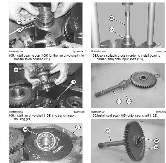
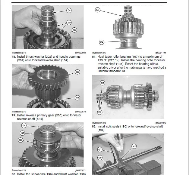
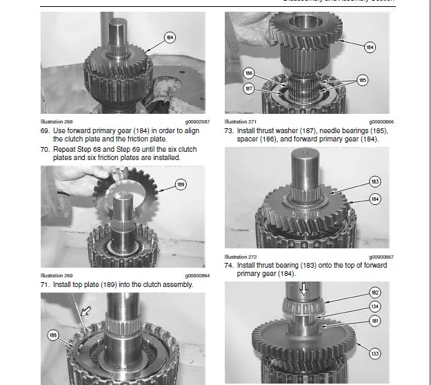
Disassembly Procedure................................................................................. 165
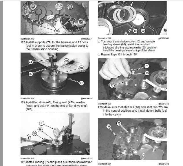
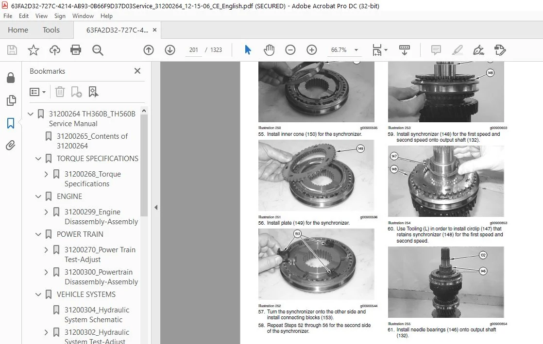
Transmission - Assemble................................................................................... 193
Assembly Procedure.................................................................................... 193
Transmission - Install.................................................................................... 221
Installation Procedure................................................................................ 221
Drive Shaft (Front) - Remove and Install.................................................................. 223
Removal Procedure..................................................................................... 223
Installation Procedure................................................................................ 224
Drive Shaft (Rear) - Remove and Install................................................................... 224
Removal Procedure..................................................................................... 224
Installation Procedure................................................................................ 225
Drive and Steering Axle (Front) - Remove.................................................................. 225
Removal Procedure..................................................................................... 225
Drive and Steering Axle (Front) - Install................................................................. 230
Installation Procedure................................................................................ 230
Drive and Steering Axle (Rear) - Remove................................................................... 234
Removal Procedure..................................................................................... 234
Drive and Steering Axle (Rear) - Install.................................................................. 237
Tie Rod (Steering) - Remove and Install................................................................... 241
Removal Procedure..................................................................................... 241
Installation procedure................................................................................ 241
Steering Cylinder - Remove and Install.................................................................... 242
Removal Procedure..................................................................................... 242
Installation Procedure................................................................................ 243
Final Drive Planetary - Remove............................................................................ 244
Removal Procedure..................................................................................... 244
Final Drive Planetary Disassemble......................................................................... 245
Disassembly Procedure................................................................................. 245
Final Drive Planetary Assemble............................................................................ 245
Assembly Procedure.................................................................................... 245
Final Drive Planetary - Install........................................................................... 246
Installation Procedure................................................................................ 246
Axle Housing and Flange Remove............................................................................ 246
Removal Procedure..................................................................................... 246
Axle Housing and Flange - Disassemble..................................................................... 249
Disassembly Procedure................................................................................. 249
Axle Housing and Flange - Assemble........................................................................ 251
Assembly Procedure.................................................................................... 251
Axle Housing and Flange Install........................................................................... 253
Installation Procedure................................................................................ 253
Axle Shaft - Remove and Install........................................................................... 256
Removal Procedure..................................................................................... 256
Installation Procedure................................................................................ 257
Axle Housing (Service Brakes, Differential and Bevel Gear) (Front) - Remove............................... 258
Removal Procedure..................................................................................... 258
Axle Housing (Service Brakes, Differential and Bevel Gear) (Front) - Disassemble.......................... 259
Disassembly Procedure................................................................................. 259
Axle Housing (Service Brakes, Differential and Bevel Gear) (Front) - Assemble............................. 264
Assembly Procedure.................................................................................... 264
Axle Housing (Service Brakes, Differential and Bevel Gear) (Front) - Install.............................. 274
Installation Procedure................................................................................ 274
Axle Housing (Differential and Bevel Gear) (Rear) - Remove................................................ 275
Removal Procedure..................................................................................... 275
Axle Housing (Differential and Bevel Gear) (Rear) - Disassemble........................................... 276
Disassembly Procedure................................................................................. 276
Axle Housing (Differential and Bevel Gear) (Rear) - Assemble.............................................. 279
Assembly Procedure.................................................................................... 279
Axle Housing (Differential and Bevel Gear) (Rear) - Install............................................... 285
Installation Procedure................................................................................ 285
Parking Brake Control -Remove and Install................................................................. 285
Removal Procedure..................................................................................... 285
Installation Procedure................................................................................ 286
Parking Brake - Remove.................................................................................... 287
Removal Procedure..................................................................................... 287
Parking Brake - Disassemble............................................................................... 288
Disassembly Procedure................................................................................. 288
Parking Brake - Assemble.................................................................................. 289
Assembly Procedure.................................................................................... 289
Parking Brake - Install................................................................................... 291
Installation Procedure................................................................................ 291
Brake Cylinder (Master) Remove and Install................................................................ 292
Removal Procedure..................................................................................... 292
Installation Procedure................................................................................ 294
Tire and Rim - Remove and Install......................................................................... 295
Removal Procedure..................................................................................... 295
Installation Procedure................................................................................ 296
VEHICLE SYSTEMS....................................................................................................... 302
31200304_Hydraulic System Schematic............................................................................... 302
31200302_Hydraulic System Test-Adjust............................................................................. 304
Table of Contents............................................................................................. 4
Systems Operation Section..................................................................................... 310
Graphic Color Codes....................................................................................... 310
Introduction.............................................................................................. 311
General Information....................................................................................... 312
Main Control Valve Group (Implement).................................................................. 312
Electronic Pilot Valve Group (Implement).............................................................. 313
Stabilizer Control Valve Gp (If Equipped)............................................................. 314
Machine ECM........................................................................................... 315
Electronic Joystick................................................................................... 317
Operator Switches..................................................................................... 318
Piston Pump (Implement and Steering).................................................................. 318
Hydraulic Oil Tank.................................................................................... 318
Hydraulic Oil Filter.................................................................................. 318
System Operation...................................................................................... 318
Load Independent Flow Division (LIFD)................................................................. 320
Location of Electrical Components......................................................................... 320
Switch (Lockout Control).............................................................................. 320
Joystick Control...................................................................................... 321
Sensor (Boom Raise/Lower)............................................................................. 322
Sensor for Boom Extend and Boom Retract or Boom Tilt Forward and Tilt Rackback........................ 322
Switch for Boom Extend and Boom Retract or Boom Tilt Forward and Tilt Rackback........................ 322
Switch (Auxiliary Actuator in the + Direction) for Joystick (Type 1).................................. 322
Switch (Auxiliary Actuator in the - Direction) for Joystick (Type 1).................................. 322
Switch (Auxiliary Actuator) for Joystick (Type 2)..................................................... 322
Switch (Auxiliary 1 or 2)............................................................................. 322
Switch (Continuous Auxiliary Flow).................................................................... 322
Switch (Quick Coupler)................................................................................ 323
Switch (Right Stabilizer)............................................................................. 323
Switch (Left Stabilizer).............................................................................. 323
Switch (Frame Level).................................................................................. 323
Pressure Switches (Stabilizer)........................................................................ 324
Switch (Fully Lowered Boom)........................................................................... 324
Switch (Critical Angle)............................................................................... 324
Switch (Fully Retracted Boom)......................................................................... 324
Machine (ECM)......................................................................................... 325
Main Control Valve (Implement)........................................................................ 325
Stabilizer Control Valve Gp (If Equipped)............................................................. 325
Solenoids (Frame Level)............................................................................... 326
Solenoid (Diverter Valve)............................................................................. 326
Relay (Frame Level)................................................................................... 326
Relays (Diverter Valve)............................................................................... 327
Relays (Quick Coupler)................................................................................ 327
Location of Hydraulic Components.......................................................................... 327
Hydraulic Tank........................................................................................ 327
Piston Pump (Implement and Steering).................................................................. 328
Compensator Valve..................................................................................... 328
Main Control Valve (Implement)........................................................................ 328
Inlet Manifold........................................................................................ 329
Outlet Manifold....................................................................................... 330
Boom Cylinder......................................................................................... 330
Load Control Valve (Boom Cylinder) (Lock)............................................................. 330
Telescoping Cylinder.................................................................................. 330
Load Control Valve (Telescoping Cylinder) (Lock)...................................................... 331
Tilt Cylinder......................................................................................... 331
Load Control Valve (Tilt Cylinder) (Lock)............................................................. 331
Compensating Cylinders................................................................................ 331
Diverter Valve........................................................................................ 332
Quick Coupler Cylinder................................................................................ 332
Frame Leveling Cylinder............................................................................... 6
Lock Valve (Frame Leveling Cylinder).................................................................. 333
Control Valve Gp (Stabilizer)......................................................................... 333
Stabilizer Cylinders.................................................................................. 333
Load Control Valve (Stabilizer Cylinders) (Lock)...................................................... 334
Lowering Control Pump (Manual)........................................................................ 334
Switches.............................................................................................. 335
Joystick Control...................................................................................... 336
Auxiliary Switches.................................................................................... 336
Thumb Slider.......................................................................................... 336
Stabilizer Switches................................................................................... 336
Boom Critical Angle Switch............................................................................ 336
Boom Retracted Switch................................................................................. 336
Stabilizer Pressure Switches.......................................................................... 337
Quick Coupler Switch.................................................................................. 337
Continuous Flow SwitchImplement....................................................................... 337
Lockout Switch........................................................................................ 337
Boom Lowered Switch................................................................................... 337
Electronic Control Module................................................................................. 338
Inputs................................................................................................ 338
Outputs............................................................................................... 338
Data Links............................................................................................ 338
Input/Output.......................................................................................... 338
Electrical Output Components.............................................................................. 342
Relays................................................................................................ 343
Solenoids............................................................................................. 343
Electrical Function Requirements.......................................................................... 344
Transmission Neutralizer.............................................................................. 344
Solenoid Outputs...................................................................................... 344
System Voltage........................................................................................ 344
Shuttle Shift for the Power Shuttle Transmission...................................................... 344
Shift Lever (Cat Data Link) for Powersynchro Transmission............................................. 344
Rear Axle Lock (if equipped).......................................................................... 344
Machine Security System............................................................................... 345
Parking Brake......................................................................................... 345
Service Brake Pressure Switch for the Transmission Neutralizer........................................ 345
More Electrical Function Requirements................................................................. 345
Steering.............................................................................................. 345
The Neutral Start Is Disabled......................................................................... 345
Stabilizer Raise/Lower (if equipped) is Disabled...................................................... 346
Boom Raise/Lower Is Disabled.......................................................................... 346
The Boom Extend/Retract Is Disabled................................................................... 346
Disable The Rackback And Dump......................................................................... 346
The Frame Level (if equipped) is Disabled............................................................. 347
Disable the Quick Coupler............................................................................. 347
Miscellaneous......................................................................................... 347
Electrical Schematic.................................................................................. 348
Piston Pump (Implement and Steering)...................................................................... 350
Piston Pump........................................................................................... 350
Compensator Valve..................................................................................... 351
Low Pressure Standby.................................................................................. 352
Upstroke.............................................................................................. 353
Constant Flow......................................................................................... 354
Destroke.............................................................................................. 355
High Pressure Stall................................................................................... 357
Main Control Valve (Implement)............................................................................ 358
Check and Relief Valves................................................................................... 361
Manifold Valve (Outlet)................................................................................... 363
Pilot Hydraulic System.................................................................................... 364
Lowering Control Pump (Electric).......................................................................... 365
Electric Lowering Control Pump (If Equipped).......................................................... 365
Lowering Control Pump (Manual)........................................................................ 368
Boom Hydraulic System..................................................................................... 370
Control valve (implement)............................................................................. 370
Valve for the Cylinder in the HOLD Position........................................................... 371
Valve for the Cylinder in the EXTEND Position......................................................... 372
Valve for the Cylinder in the RETRACT Position........................................................ 373
Load Control Valves................................................................................... 374
Lowering Control Valve (If Equipped).................................................................. 375
Boom RAISE............................................................................................ 376
Boom LOWER............................................................................................ 377
Telescoping System........................................................................................ 378
Valve for the Telescoping Cylinder in the HOLD Position............................................... 378
Valve for the Telescoping Cylinder in the EXTEND Position............................................. 380
Valve for the Telescoping Cylinder in the RETRACT Position............................................ 382
Auxiliary Hydraulic System................................................................................ 384
Introduction.......................................................................................... 384
Auxiliary Control (Combined Circuit).................................................................. 385
Auxiliary Circuit 1................................................................................... 387
Auxiliary Circuit 2................................................................................... 388
Continuous Flow (Auxiliary Hydraulics)................................................................ 389
Quick Coupler......................................................................................... 389
Quick Coupler Circuit DISENGAGED...................................................................... 390
Quick Coupler Pins ENGAGED............................................................................ 391
Relief Valves and Makeup Valves....................................................................... 392
Compensating System....................................................................................... 392
Boom Lower............................................................................................ 393
Boom Raise............................................................................................ 394
Pressure Relief and Makeup Valves..................................................................... 395
Frame Leveling System..................................................................................... 396
Locked Axle (HOLD).................................................................................... 397
Frame that is Angled to the Left...................................................................... 398
Stabilizer System......................................................................................... 399
Stabilizer Cylinders (HOLD)........................................................................... 401
Stabilizer Cylinders (RAISE).......................................................................... 402
Stabilizer Cylinders (LOWER).......................................................................... 403
Hydraulic System Schematic................................................................................ 404
All Implements In HOLD................................................................................ 404
Configuration Parameters.............................................................................. 407
Testing and Adjusting Section................................................................................. 408
Testing and Adjusting..................................................................................... 408
Joystick Control - Calibrate.......................................................................... 408
Main Control Valve (Implement) - Calibrate................................................................ 428
Programmable Hydraulic System (PHS) Valve Calibrations................................................ 428
Manual Adjustment After Calibrating The Valves........................................................ 437
Hydraulic System Pressure - Release....................................................................... 437
Relieving Pressure in the Hydraulic System............................................................ 438
Lock Valve Locations.................................................................................. 438
Location of the Shutoff Valve for the Axle Lock....................................................... 439
Relieving Pressure from the Lock Valves............................................................... 439
Verifying the Correct Setting of the Load Control Valves.............................................. 443
Relieving Pressure from the Shutoff Valve on the Axle Lock............................................ 443
Hydraulic System Pressures - Test and Adjust.............................................................. 443
Test and Adjustment Procedures........................................................................ 443
Pilot Pressure (Pressure Reducing Valve) - Test and Adjust................................................ 444
Pilot Pressure Test................................................................................... 444
Warming the Transmission Oil.......................................................................... 444
Test Procedure........................................................................................ 444
Pressure Reducing Valve Adjustment.................................................................... 445
Relief Valve (Implement) - Test and Adjust................................................................ 446
Auxiliary Pressure Test (Port A and Portable.......................................................... 446
Warming the Transmission Oil.......................................................................... 446
Test Procedure........................................................................................ 447
Auxiliary Relief Valve Adjustments.................................................................... 447
Pressure Adjustment for Disengaging the Quick Coupler................................................. 447
Pressure Adjustment for Engaging the Quick Coupler.................................................... 448
Hydraulic Oil Contamination - Test........................................................................ 448
Hydraulic Oil Contamination........................................................................... 448
Flushing the Sampling Valve........................................................................... 448
In order to obtain a representative oil sample, it is first necessary to flush the sampling valve..... 448
Obtaining the Sample.................................................................................. 449
Maximum Contamination Levels.......................................................................... 449
Boom Chain - Clean/Inspect/ Lubricate..................................................................... 449
Boom Chains........................................................................................... 449
Check Condition....................................................................................... 449
Cleaning and Inspection............................................................................... 449
General Information Table................................................................................. 450
31200273_Steering System Test-Adjust.............................................................................. 458
Table of Contents............................................................................................. 4
Systems Operation Section..................................................................................... 462
Graphic Color Codes....................................................................................... 462
General Information....................................................................................... 463
Steering Arrangement.................................................................................. 463
Introduction.............................................................................................. 465
Location of Electrical Components......................................................................... 466
Selector Switch for the Steering Mode................................................................. 466
Position Sensors...................................................................................... 466
Electronic Control Module............................................................................. 467
Solenoid for Crab Steer............................................................................... 467
Solenoid for Circle Steer............................................................................. 467
Relay (Crab Steer).................................................................................... 467
Relay (Circle Steer).................................................................................. 468
Location of Hydraulic Components.......................................................................... 468
Steering Wheel........................................................................................ 468
Metering Pump......................................................................................... 469
Piston Pump........................................................................................... 469
Line for the Signal Limiter Valve for the Steering.................................................... 469
Priority Valve........................................................................................ 34
Control Valve (Steering).............................................................................. 470
Steering Cylinders.................................................................................... 470
Hydraulic Tank........................................................................................ 470
Hydraulic Tank Breather............................................................................... 470
Hydraulic Oil Level Indicator......................................................................... 471
Hydraulic Oil Drain Plugs............................................................................. 471
Electrical Input Components............................................................................... 471
Steering Mode Switch.................................................................................. 471
Position Sensor....................................................................................... 472
Electronic Control Module................................................................................. 472
Electrical Output Components.............................................................................. 473
Relays................................................................................................ 473
Instrument Cluster.................................................................................... 473
Data Link................................................................................................. 473
CAT Data Link......................................................................................... 473
CAN Data Link......................................................................................... 474
Electrical Schematic...................................................................................... 474
Inlet Manifold............................................................................................ 474
Steering Priority Valve............................................................................... 475
Screens (75 and 100 Micron)........................................................................... 475
Flow Control Valve (Dump valve for the load sensing oil).............................................. 475
Relief Valve (Load sensing oil)....................................................................... 475
Check Valve........................................................................................... 475
Steering Not Activated................................................................................ 476
Steering Activated.................................................................................... 477
Steering System........................................................................................... 478
Steering Control System............................................................................... 478
Steering in Neutral................................................................................... 479
Right Turn in Two-Wheel Steer Mode.................................................................... 481
Left Turn in Circle Steer Mode........................................................................ 483
Left Turn in Crab Steer Mode.......................................................................... 485
Hydraulic Schematic (Steering System)..................................................................... 487
Piston Pump (Implement and Steering)...................................................................... 488
Piston Pump........................................................................................... 488
Compensator Valve..................................................................................... 489
Low Pressure Standby.................................................................................. 490
Upstroke.............................................................................................. 491
Constant Flow......................................................................................... 492
Destroke.............................................................................................. 493
High Pressure Stall................................................................................... 495
Solenoid Valve (Steering Mode Selector)................................................................... 496
Solenoid Valve........................................................................................ 53
Metering Pump (Steering).................................................................................. 496
Hold.................................................................................................. 498
Right Turn............................................................................................ 499
Position Sensor (Steering)................................................................................ 501
Configuration Parameters.................................................................................. 502
Testing and Adjusting Section................................................................................. 504
Hydraulic Oil Contamination - Test........................................................................ 504
Hydraulic Oil Contamination........................................................................... 504
Flushing the Sampling Valve........................................................................... 504
Obtaining the Sample.................................................................................. 504
Pump Flow - Test.......................................................................................... 505
Pump Flow............................................................................................. 505
Test On The Machine................................................................................... 505
Test On The Bench..................................................................................... 506
Steering System Pressures - Test and Adjust............................................................... 506
Steering System Pressure Tests and Adjustments........................................................ 506
Steering Pressure Test................................................................................ 507
Steering Pressure Adjustment.......................................................................... 507
Margin Pressure Test.................................................................................. 508
Margin Pressure Adjustment............................................................................ 509
Test for the Relief Valve (Load Sensing Oil).......................................................... 509
Adjustment of the Relief Valve (Load Sensing Oil)..................................................... 510
Test for Pressure Compensator......................................................................... 510
Pressure Compensator Adjustment....................................................................... 511
Low Pressure Standby Test............................................................................. 511
Low Pressure Standby Adjustment....................................................................... 512
Steering System - Purge................................................................................... 513
Purging the Steering System........................................................................... 513
Solenoid Valve (Steering Mode Selector) - Test............................................................ 513
The Solenoid's for the Steering Modes................................................................. 513
Position Sensor (Steering) - Adjust....................................................................... 514
Position Sensor....................................................................................... 514
Wheel Alignment - Check and Adjust........................................................................ 516
Checking the Wheel Alignment With Wheels In Place..................................................... 517
Adjusting the Wheel Alignment......................................................................... 517
Adjusting the Steering Angle.......................................................................... 518
General Information Table................................................................................. 519
31200274_Braking System Test-Adjust............................................................................... 524
Table of Contents............................................................................................. 4
Systems Operation Section..................................................................................... 528
Graphic Color Codes....................................................................................... 528
Introduction.............................................................................................. 529
General Information....................................................................................... 530
Brake Packs........................................................................................... 530
Brake Pedal........................................................................................... 530
Brake Cylinder........................................................................................ 530
Service Brake Pressure Switch......................................................................... 531
Parking Brake Lever................................................................................... 531
Location of Electrical Components......................................................................... 531
Parking Brake Switch.................................................................................. 531
Service Brake Pressure Switch......................................................................... 531
Stoplight Switch...................................................................................... 531
Location of Components (Braking).......................................................................... 532
Parking Brake Lever................................................................................... 532
Parking Brake Actuator................................................................................ 532
Service Brake Pedal................................................................................... 532
Brake Cylinder........................................................................................ 533
Service Brake Discs................................................................................... 533
Service Brake............................................................................................. 533
Service Brake......................................................................................... 533
The Service Brake System with the Brakes Disengaged................................................... 535
The Service Brake System with the Brakes Engaged...................................................... 536
Parking Brake............................................................................................. 537
Engaging the Parking Brake............................................................................ 537
Disengaging the Parking Brake......................................................................... 538
Brake Cylinder (Master)................................................................................... 539
Brake Cylinder with the Brakes Disengaged............................................................. 540
Brake Cylinder with the Brakes Engaged................................................................ 542
Hydraulic Schematic (Braking System)...................................................................... 544
Configuration Parameters.................................................................................. 545
Electrical Function Requirements.......................................................................... 546
Transmission Neutralizer.............................................................................. 546
System Voltage........................................................................................ 546
Shuttle Shift for the Power Shuttle Transmission...................................................... 546
Shift Lever (Cat Data Link) for Powersynchro Transmission............................................. 546
Rear Axle Lock (if equipped).......................................................................... 462
Machine Security System............................................................................... 462
Parking Brake......................................................................................... 546
Service Brake Pressure Switch for the Transmission Neutralizer........................................ 547
More Electrical Function Requirements..................................................................... 547
Steering.............................................................................................. 547
The Neutral Start Is Disabled......................................................................... 463
Stabilizer Raise/Lower (if equipped) is Disabled...................................................... 548
Boom Raise/Lower Is Disabled.......................................................................... 548
The Boom Extend/Retract Is Disabled................................................................... 548
Disable The Rackback And Dump......................................................................... 548
The Frame Level (if equipped) is Disabled............................................................. 549
Disable the Quick Coupler............................................................................. 549
Miscellaneous......................................................................................... 549
Testing and Adjusting Section................................................................................. 550
Testing and Adjusting Service Brake - Test................................................................ 550
Holding Ability Test for the Service Brakes........................................................... 550
Stopping Performance Test for the Service Brakes...................................................... 550
Service Brake Control - Check and Adjust.................................................................. 550
Adjusting the Brake Pedal Linkage..................................................................... 550
Service Brake Discs - Check............................................................................... 552
Checking the Wear on the Service Brake Discs.......................................................... 552
Procedure for Checking the Wear....................................................................... 552
Service Brake Air - Purge................................................................................. 553
Purging Air from the Braking System................................................................... 553
Parking Brake - Test...................................................................................... 554
Holding Ability Test for the Parking Brake............................................................ 554
Parking Brake Control - Check and Adjust.................................................................. 555
Adjusting the Parking Brake Control Cable............................................................. 555
31200306_Machine Components Specifications........................................................................ 562
Table of Contents............................................................................................. 4
Specifications Section........................................................................................ 566
Hydraulic Tank............................................................................................ 566
Hydraulic Tank............................................................................................ 568
Hydraulic Tank............................................................................................ 569
Piston Pump (Implement and Steering)...................................................................... 464
Solenoid Valve (Pilot Selector)........................................................................... 571
Main Control Valve (Implement)............................................................................ 572
Frame..................................................................................................... 574
Boom...................................................................................................... 575
Boom...................................................................................................... 576
Boom Cylinder............................................................................................. 577
Boom Cylinder............................................................................................. 578
Boom Cylinder............................................................................................. 579
Load Control Valve (Boom Cylinder) (Lock)................................................................. 580
Compensating Cylinder..................................................................................... 581
Compensating Cylinder..................................................................................... 582
Telescoping Cylinder...................................................................................... 583
Load Control Valve (Telescoping Cylinder) (Lock).......................................................... 584
Tilt Cylinder............................................................................................. 585
Tilt Cylinder............................................................................................. 586
Load Control Valve (Tilt Cylinder) (Lock)................................................................. 587
Diverter Valve............................................................................................ 587
Diverter Valve............................................................................................ 588
Towing Hitch.............................................................................................. 589
Towing Hitch.............................................................................................. 589
Towing Hitch.............................................................................................. 590
Towing Hitch.............................................................................................. 590
Towing Hitch.............................................................................................. 591
Towing Hitch.............................................................................................. 591
Frame Leveling Cylinder................................................................................... 592
Frame Leveling Cylinder................................................................................... 593
Load Control Valve (Frame Leveling Cylinder) (Lock)....................................................... 594
Control Valve (Stabilizer)................................................................................ 595
Stabilizer Cylinder....................................................................................... 596
Stabilizer Cylinder....................................................................................... 597
Stabilizer Cylinder....................................................................................... 598
Load Control Valve (Stabilizer Cylinder) (Lock)........................................................... 599
Axle Lock Cylinder........................................................................................ 600
Metering Pump (Steering).................................................................................. 601
Solenoid Valve (Steering Mode Selector)................................................................... 601
Position Sensor (Steering)................................................................................ 602
Position Sensor (Steering)................................................................................ 602
Flexible Coupling Drive................................................................................... 603
Transmission.............................................................................................. 604
Transmission.............................................................................................. 606
Position Sensor (Transmission)............................................................................ 608
Oil Filter................................................................................................ 609
Hydraulic Oil Cooler...................................................................................... 611
Drive Shaft............................................................................................... 612
Drive and Steering Axle (Front)........................................................................... 613
271 -6425 Drive and Steering Axle Gp.................................................................. 613
271 -6426 Drive and Steering Axle Gp.................................................................. 615
Drive and Steering Axle (Front)........................................................................... 617
271 -6427 Drive and Steering Axle Gp, with Steering Sensor............................................ 617
Drive and Steering Axle (Rear)............................................................................ 619
189-5717 Drive and Steering Axle Gp, with Steering Sensor............................................. 619
168-7443 Drive and Steering Axle Gp, with Steering Sensor............................................. 620
Drive and Steering Axle (Rear)............................................................................ 621
231 -0710 Drive and Steering Axle Gp, without Steering Sensor......................................... 621
231 -0709 Drive and Steering Axle Gp, with Steering Sensor............................................ 622
Differential and Bevel Gear Group......................................................................... 623
Differential and Bevel Gear Group......................................................................... 624
Axle Housing and Flange Group............................................................................. 625
Axle Housing and Flange Group............................................................................. 625
Final Drive Planetary Group............................................................................... 626
Final Drive Planetary Group............................................................................... 627
Axle Housing Group (Differential and Brake Cylinder)...................................................... 628
174-4642 Axle Housing Gp with a Locking Differential.................................................. 628
219-8780 Axle Housing Gp.............................................................................. 630
219-8831 Axle Housing Gp with a Locking Differential.................................................. 632
219-8842 Axle Housing Gp without a Locking Differential............................................... 634
Axle Housing Group (Differential and Brake Cylinder)...................................................... 636
253-4990 Axle Housing Gp with a Locking Differential.................................................. 636
253-4985 Axle Housing Gp without a Locking Differential............................................... 638
Brake Cylinder (Master)................................................................................... 639
Parking Brake Control..................................................................................... 640
Parking Brake............................................................................................. 641
Fender.................................................................................................... 642
Wheel (Tire and Rim)...................................................................................... 643
Fuel Tank................................................................................................. 644
Fuel Tank................................................................................................. 645
Engine Enclosure.......................................................................................... 646
Engine and Transmission Mounting.......................................................................... 648
Air Cleaner............................................................................................... 649
Engine Oil Drain.......................................................................................... 651
Muffler................................................................................................... 652
Suction Fan............................................................................................... 653
Battery................................................................................................... 654
Alternator................................................................................................ 655
Coolant Lines Group....................................................................................... 656
Coolant Recovery Group.................................................................................... 657
Cab....................................................................................................... 659
Latch Adjustment...................................................................................... 659
Cab Mounting.............................................................................................. 660
Cab Door.................................................................................................. 661
Access Door............................................................................................... 663
Joystick Control.......................................................................................... 664
Steering Wheel and Column................................................................................. 665
Window Wiper and Wiper Motor.............................................................................. 666
Window Washer Tank........................................................................................ 667
Rear View Mirror.......................................................................................... 668
Carriage Cylinder (Rotate)................................................................................ 668
Carriage Cylinder (Sideshift)............................................................................. 669
Hydraulic Cylinder (Multipurpose Bucket).................................................................. 670
Grapple Cylinder.......................................................................................... 671
31200308_Machine Systems Disassembly-Assembly..................................................................... 676
Table of Contents............................................................................................. 4
Disassembly and Assembly Section.............................................................................. 682
Hydraulic System Pressure - Release....................................................................... 682
Release Procedure..................................................................................... 682
Steering Wheel - Remove and Install....................................................................... 682
Removal Procedure..................................................................................... 682
Installation Procedure................................................................................ 683
Metering Pump (Steering) - Remove......................................................................... 683
Removal Procedure..................................................................................... 683
Metering Pump (Steering) - Install........................................................................ 686
Installation Procedure................................................................................ 686
Steering Column - Remove.................................................................................. 688
Removal Procedure..................................................................................... 688
Steering Column - Install................................................................................. 691
Installation Procedure................................................................................ 691
Main Control Valve (Implement) - Remove................................................................... 694
Removal Procedure..................................................................................... 694
Electronic Pilot Valve - Remove and Install............................................................... 696
Removal Procedure..................................................................................... 696
Installation Procedure................................................................................ 698
Bank Valve (Implement) - Disassemble...................................................................... 699
Disassembly Procedure................................................................................. 699
Bank Valve (Implement) - Assemble......................................................................... 705
Assembly Procedure.................................................................................... 705
Main Control Valve (Implement) - Install.................................................................. 712
Installation Procedure................................................................................ 712
Solenoid Valve (Steering Mode Selector) - Remove and Install.............................................. 714
Removal Procedure..................................................................................... 714
Installation Procedure................................................................................ 715
Master Cylinder (Brake) - Remove.......................................................................... 716
Removal Procedure..................................................................................... 716
Master Cylinder (Brake) - Install......................................................................... 331
Installation Procedure................................................................................ 717
Hydraulic Tank - Remove................................................................................... 719
Removal Procedure..................................................................................... 719
Hydraulic Tank - Install.................................................................................. 720
Installation Procedure................................................................................ 720
Piston Pump (Implement and Steering) - Remove............................................................. 721
Removal Procedure..................................................................................... 721
Piston Pump (Implement and Steering) - Disassemble........................................................ 723
Disassembly Procedure................................................................................. 83
Piston Pump (Implement and Steering) - Assemble........................................................... 727
Assembly Procedure.................................................................................... 727
Piston Pump (Implement and Steering) - Install............................................................ 732
Installation Procedure................................................................................ 732
Solenoid Valve (Frame Leveling) - Remove and Install...................................................... 733
Removal Procedure..................................................................................... 733
Installation Procedure................................................................................ 733
Diverter Valve (Boom Head) - Remove and Install........................................................... 734
Removal Procedure..................................................................................... 734
Installation Procedure................................................................................ 734
Control Valve (Stabilizer) - Remove....................................................................... 735
Removal Procedure..................................................................................... 735
Electronic Pilot Valve (Stabilizer) - Remove and Install.................................................. 736
Removal Procedure..................................................................................... 736
Installation Procedure................................................................................ 737
Bank Valve (Stabilizer) - Disassemble..................................................................... 737
Disassembly Procedure................................................................................. 737
Bank Valve (Stabilizer) - Assemble........................................................................ 740
Assembly Procedure.................................................................................... 740
Control Valve (Stabilizer) -Install....................................................................... 742
Installation Procedure................................................................................ 742
Stabilizer Cylinder - Remove and Install.................................................................. 744
Removal Procedure..................................................................................... 744
Disassembly and Assembly Information.................................................................. 746
Installation Procedure................................................................................ 748
Load Control Valve (Stabilizer Cylinder) - Remove and Install............................................. 749
Removal Procedure..................................................................................... 749
Installation Procedure................................................................................ 750
Fuel Tank - Remove........................................................................................ 750
Removal Procedure..................................................................................... 355
Fuel Tank - Install....................................................................................... 752
Installation Procedure................................................................................ 752
Cab - Remove.............................................................................................. 753
Removal Procedure..................................................................................... 753
Cab - Install............................................................................................. 757
Installation Procedure................................................................................ 757
Window Wiper and Wiper Motor (Front) - Remove and Install................................................. 760
Removal Procedure..................................................................................... 760
Installation Procedure................................................................................ 761
Window Wiper and Wiper Motor (Rear) - Remove and Install.................................................. 762
Removal Procedure..................................................................................... 762
Installation Procedure................................................................................ 763
Window Wiper and Wiper Motor (Roof) - Remove and Install.................................................. 764
Removal Procedure..................................................................................... 764
Installation procedure.................................................................................... 765
Cab Heater - Remove....................................................................................... 766
Removal Procedure..................................................................................... 766
Cab Heater - Install...................................................................................... 768
Installation Procedure................................................................................ 768
Heater Coil - Remove and Install.......................................................................... 770
Removal Procedure..................................................................................... 770
Installation Procedure................................................................................ 771
Air Conditioner - Install................................................................................. 771
Installation Procedure................................................................................ 771
Evaporator Coil - Remove and Install...................................................................... 776
Removal Procedure..................................................................................... 776
Installation procedure................................................................................ 777
Joystick Control - Remove and Install..................................................................... 778
Removal Procedure..................................................................................... 778
Installation Procedure................................................................................ 779
Seat - Remove and Install................................................................................. 779
Removal Procedure..................................................................................... 779
Installation Procedure................................................................................ 780
Fender - Remove and Install............................................................................... 780
Removal Procedure..................................................................................... 780
Installation Procedure................................................................................ 780
Sump Guard - Remove and Install........................................................................... 781
Removal Procedure..................................................................................... 781
Installation Procedure................................................................................ 781
Counterweight - Remove and Install........................................................................ 781
Removal Procedure..................................................................................... 781
Installation Procedure................................................................................ 783
Quick Coupler - Remove.................................................................................... 784
Removal Procedure..................................................................................... 784
Quick Coupler - Disassemble............................................................................... 786
Disassembly Procedure................................................................................. 786
Quick Coupler - Assemble.................................................................................. 788
Assembly Procedure.................................................................................... 788
Quick Coupler - Install................................................................................... 789
Installation Procedure................................................................................ 789
Boom - Remove............................................................................................. 791
Removal Procedure..................................................................................... 791
Boom - Disassemble........................................................................................ 793
Disassembly Procedure................................................................................. 793
Boom - Assemble........................................................................................... 799
Assembly Procedure.................................................................................... 799
Boom - Install............................................................................................ 808
Installation Procedure................................................................................ 808
Hydraulic Oil Lines (Boom) - Remove....................................................................... 810
Removal Procedure..................................................................................... 810
Tilt Cylinder Hoses (Boom)............................................................................ 811
Auxiliary Hoses (Boom)................................................................................ 814
Hydraulic Oil Lines (Boom) - Install...................................................................... 817
Installation Procedure................................................................................ 817
Telescoping Cylinder - Remove and Install................................................................. 824
Removal Procedure..................................................................................... 824
Disassembly and Assembly Information.................................................................. 829
Installation Procedure................................................................................ 830
Load Control Valve (Telescoping Cylinder) - Remove and Install............................................ 835
Removal Procedure..................................................................................... 835
Installation Procedure................................................................................ 836
Boom Cylinder - Remove and Install........................................................................ 837
Removal Procedure..................................................................................... 837
Disassembly and Assembly Information.................................................................. 839
Installation Procedure................................................................................ 840
Load Control Valve (Boom Cylinder) - Remove and Install................................................... 842
Removal Procedure..................................................................................... 842
Installation Procedure................................................................................ 843
Tilt Cylinder - Remove and Install........................................................................ 843
Removal Procedure..................................................................................... 843
Disassembly and Assembly Information.................................................................. 845
Installation Procedure................................................................................ 846
Load Control Valve (Tilt Cylinder) - Remove and Install................................................... 848
Removal Procedure..................................................................................... 848
Installation Procedure................................................................................ 848
Frame Leveling Cylinder - Remove and Install.............................................................. 849
Removal Procedure..................................................................................... 849
Disassembly and Assembly Information.................................................................. 851
Installation Procedure................................................................................ 852
Load Control Valve (Frame Leveling Cylinder) - Remove and Install......................................... 854
Removal Procedure..................................................................................... 854
Installation Procedure................................................................................ 855
Compensating Cylinder Remove and Install.................................................................. 855
Removal Procedure..................................................................................... 855
Disassembly and Assembly Information.................................................................. 857
Installation Procedure................................................................................ 858
Axle Lock Cylinder - Remove and Install................................................................... 859
Removal Procedure..................................................................................... 859
Disassembly and Assembly Information.................................................................. 862
Installation Procedure................................................................................ 863
Shutoff Valve (Axle Lock) - Remove and Install............................................................ 865
Removal Procedure..................................................................................... 865
Installation Procedure................................................................................ 865
Stabilizer - Remove....................................................................................... 866
Removal Procedure..................................................................................... 866
Stabilizer - Install...................................................................................... 869
Installation Procedure................................................................................ 869
Stabilizer............................................................................................ 873
ELECTRICAL SYSTEMS.................................................................................................... 881
31200310_TH360B Electrical System Schematic....................................................................... 882
31200311_TH560B Electrical System Schematic....................................................................... 886
31200279_Electronic Control System, Hydrostatic Transmission Troubleshooting Test-Adjust.......................... 890
Table of Contents............................................................................................. 892
Introduction.................................................................................................. 896
General Information....................................................................................... 896
Service Tools............................................................................................. 896
Connector Locations....................................................................................... 897
Connector Contact Numbers............................................................................. 897
Diagnostic Capabilities................................................................................... 898
Monitoring System/Instrument Cluster.................................................................. 898
The Caterpillar Electronic Technician (ET)............................................................ 899
Logged Event Codes.................................................................................... 900
Status Groups For The Electronic Technician........................................................... 901
Machine Preparation for Troubleshooting................................................................... 901
General Troubleshooting Information....................................................................... 902
Visual Inspection......................................................................................... 902
Operational Checks........................................................................................ 902
Operational Checks (Braking System)................................................................... 902
Operational Checks (Steering System).................................................................. 903
Operational Checks (Power Train)...................................................................... 903
Operational Checks (Hydraulic System)................................................................. 903
Event Code List........................................................................................... 905
Warning Levels........................................................................................ 905
Indications and System Response....................................................................... 905
Troubleshooting....................................................................................... 906
Telehandler Event Code List........................................................................... 906
Symptom Procedures............................................................................................ 908
Steering System........................................................................................... 908
Troubleshooting The Steering System................................................................... 908
Brake System.............................................................................................. 909
Troubleshooting The Brake System...................................................................... 909
Troubleshooting The Parking Brake..................................................................... 910
Transmission.............................................................................................. 910
Troubleshooting The Transmission System............................................................... 910
Hydraulic System.......................................................................................... 912
Troubleshooting The Hydraulic System.................................................................. 912
Torque Converter.......................................................................................... 914
Troubleshooting The Torque Converter.................................................................. 914
Differential and Final Drive.............................................................................. 915
The Differential And The Final Drive Troubleshooting.................................................. 915
Diagnostic Code Procedures.................................................................................... 918
Diagnostic Code List...................................................................................... 918
Module Identifier (MID)............................................................................... 918
Component Identifier (CID)............................................................................ 918
Failure Mode Identifier (FMI)......................................................................... 920
Using the Operator Monitor to Determine Diagnostic Codes.................................................. 922
Using Caterpillar Electronic Technician to Determine Diagnostic Codes..................................... 922
Active Diagnostic Codes............................................................................... 923
Logged Diagnostic Codes............................................................................... 924
MID 039 - CID 0041 - FMI 03............................................................................... 925
MID 039 - CID 0041 - FMI 04............................................................................... 926
MID 039 - CID 0070 - FMI 03............................................................................... 927
MID 039 - CID 0070 - FMI 04............................................................................... 929
MID 039 - CID 0096 - FMI 03............................................................................... 930
MID 039 - CID 0096 - FMI 04............................................................................... 931
MID 039 - CID0 110 - FMI 03............................................................................... 932
MID 039 - CID 0110 - FMI 04............................................................................... 933
MID 039 - CID 0177 - FMI 03............................................................................... 934
MID 039 - CID 0177 - FMI 04............................................................................... 936
MID 039 - CID 0191 - FMI 02............................................................................... 936
MID 039 - CID 0246 - FMI 12............................................................................... 938
MID 039 - CID 0262 - FMI 03............................................................................... 939
MID 039 - CID 0262 - FMI 04............................................................................... 940
MID 039 - CID 0271 - FMI 03............................................................................... 941
MID 039 - CID 0271 - FMI 04............................................................................... 942
MID 039 - CID 0271 - FMI 05............................................................................... 943
MID 039 - CID 0368 - FMI 03............................................................................... 945
MID 039 - CID 0368 - FMI 04............................................................................... 946
MID 039 - CID 0444 - FMI 03............................................................................... 947
MID 039 - CID 0444 - FMI 04............................................................................... 948
MID 039 - CID 0444 - FMI 05............................................................................... 949
MID 039 - CID 0489 - FMI 02............................................................................... 951
MID 039 - CID 0489 - FMI 04............................................................................... 953
MID 039 - CID 0490 - FMI 02............................................................................... 955
MID 039 - CID 0590 - FMI 02............................................................................... 958
MID 039 - CID 0590 - FMI 09............................................................................... 960
MID 039 - CID 0590 - FMI 12............................................................................... 962
MID 039 - CID 0629 - FMI 04............................................................................... 964
MID 039 - CID 0668 - FMI 02............................................................................... 965
MID 039 - CID 0668 - FMI 09............................................................................... 967
MID 039 - CID 0668 - FMI 12............................................................................... 969
MID 039 - CID 0672 - FMI 02............................................................................... 971
MID 039 - CID 0702 - FMI 02............................................................................... 972
MID 039 - CID 0750 - FMI 02............................................................................... 975
MID 039 - CID 0811 - FMI 09............................................................................... 976
MID 039 - CID 0817 - FMI 04............................................................................... 978
MID 039 - CID 0826 - FMI 03............................................................................... 979
MID 039 - CID 0882 - FMI 05............................................................................... 981
MID 039 - CID 0882 - FMI 06............................................................................... 982
MID 039 - CID 1127 - FMI 00............................................................................... 983
MID 039 - CID 1127 - FMI 01............................................................................... 986
MID 039 - CID 1127 - FMI 02............................................................................... 989
MID 039 - CID 1127 - FMI 08............................................................................... 991
MID 039 - CID 1128 - FMI 00............................................................................... 994
MID 039 - CID 1128 - FMI 01............................................................................... 997
MID 039 - CID 1128 - FMI 02...............................................................................1000
MID 039 - CID 1128 - FMI 08...............................................................................1003
MID 039 - CID 1138 - FMI 05...............................................................................1006
MID 039 - CID 1138 - FMI 06...............................................................................1008
MID 039 - CID 1187 - FMI 04...............................................................................1009
MID 039 - CID 1189 - FMI 00...............................................................................1010
MID 039 - CID 1189 - FMI 01...............................................................................1013
MID 039 - CID 1189 - FMI 02...............................................................................1015
MID 039 - CID 1189 - FMI 08...............................................................................1018
MID 039 - CID 1193 - FMI 05...............................................................................1021
MID 039 - CID 1193 - FMI 06...............................................................................1023
MID 039 - CID 1251 - FMI 08...............................................................................1024
MID 039 - CID 1326 - FMI 02...............................................................................1025
MID 039 - CID 1401 - FMI 03...............................................................................1026
MID 039 - CID 1401 - FMI 05...............................................................................1027
MID 039 - CID 1401 - FMI 06...............................................................................1028
MID 039 - CID 1402 - FMI 03...............................................................................1029
MID 039 - CID 1402 - FMI 06...............................................................................1032
MID 039 - CID 1403 - FMI 03...............................................................................1033
MID 039 - CID 1403 - FMI 05...............................................................................1034
MID 039 - CID 1403 - FMI 06...............................................................................1035
MID 039 - CID 1404 - FMI 03...............................................................................1036
MID 039 - CID 1404 - FMI 05...............................................................................1037
MID 039 - CID 1404 - FMI 06...............................................................................1038
MID 039 - CID 1405 - FMI 03...............................................................................1040
MID 039 - CID 1405 - FMI 05...............................................................................1041
MID 039 - CID 1405 - FMI 06...............................................................................1042
MID 039 - CID 1406 - FMI 03...............................................................................1043
MID 039 - CID 1406 - FMI 05...............................................................................1044
MID 039 - CID 1406 - FMI 06...............................................................................1046
MID 039 - CID 1407 - FMI 03...............................................................................1047
MID 039 - CID 1407 - FMI 05...............................................................................1048
MID 039 - CID 1407 - FMI 06...............................................................................1049
MID 039 - CID 1410 - FMI 05...............................................................................1051
MID 039 - CID 1410 - FMI 06...............................................................................1053
MID 039 - CID 1482 - FMI 03...............................................................................1055
MID 039 - CID 1482 - FMI 04...............................................................................1057
MID 039 - CID 1529 - FMI 02...............................................................................1058
MID 039 - CID 1603 - FMI 09...............................................................................1060
MID 039 - CID 1639 - FMI 02...............................................................................1062
MID 039 - CID 1639 - FMI 09...............................................................................1064
MID 039 - CID 1658 - FMI 00...............................................................................1066
MID 039 - CID 1658 - FMI 01...............................................................................1069
MID 039 - CID 1658 - FMI 02...............................................................................1072
MID 039 - CID 1658 - FMI 08...............................................................................1074
MID 039 - CID 1718 - FMI 02...............................................................................1077
MID 039 - CID 1740 - FMI 03...............................................................................1079
MID 039 - CID 1740 - FMI 04...............................................................................1080
MID 039 - CID 1740 - FMI 05...............................................................................1081
MID 039 - CID 1741 - FMI 03...............................................................................1083
MID 039 - CID 1741 - FMI 04...............................................................................1084
MID 039 - CID 1741 - FMI 05...............................................................................1085
MID 039 - CID 1763 - FMI 02...............................................................................1087
MID 039 - CID 1788 - FMI 02...............................................................................1089
MID 039 - CID 1789 - FMI 02...............................................................................1090
MID 039 - CID 1820 - FMI 05...............................................................................1092
MID 039 - CID 1820 - FMI 06...............................................................................1093
MID 039 - CID 1823 - FMI 03...............................................................................1094
MID 039 - CID 1823 - FMI 04...............................................................................1096
MID 039 - CID 1823 - FMI 08...............................................................................1099
MID 039 - CID 1824 - FMI 03...............................................................................1101
MID 039 - CID 1824 - FMI 04...............................................................................1103
MID 039 - CID 1824 - FMI 08...............................................................................1105
MID 039 - CID 1825 - FMI 03...............................................................................1107
MID 039 - CID 1825 - FMI 04...............................................................................1109
MID 039 - CID 1825 - FMI 08...............................................................................1111
MID 039 - CID 1826 - FMI 00...............................................................................1113
MID 039 - CID 1826 - FMI 01...............................................................................1115
MID 039 - CID 1826 - FMI 02...............................................................................1118
MID 039 - CID 1826 - FMI 08...............................................................................1120
MID 039 - CID 1827 - FMI 13...............................................................................1121
MID 039 - CID 1828 - FMI 02...............................................................................1122
MID 039 - CID 1829 - FMI 02...............................................................................1123
MID 039 - CID 1830 - FMI 02...............................................................................1125
MID 039 - CID 1831 - FMI 05...............................................................................1127
MID 039 - CID 1831 - FMI 06...............................................................................1129
MID 039 - CID 1832 - FMI 02...............................................................................1130
MID 039 - CID 1833 - FMI 02...............................................................................1131
MID 039 - CID 1834 - FMI 03...............................................................................1132
MID 039 - CID 1845 - FMI 02...............................................................................1134
MID 039 - CID 1845 - FMI 05...............................................................................1136
MID 039 - CID 1845 - FMI 06...............................................................................1138
MID 039 - CID 1845 - FMI 09...............................................................................1140
MID 039 - CID 1846 - FMI 02...............................................................................1143
MID 039 - CID 1846 - FMI 05...............................................................................1145
MID 039 - CID 1846 - FMI 06...............................................................................1147
MID 039 - CID 1846 - FMI 09...............................................................................1149
MID 039 - CID 1847 - FMI 02...............................................................................1152
MID 039 - CID 1847 - FMI 05...............................................................................1154
MID 039 - CID 1847 - FMI 06...............................................................................1156
MID 039 - CID 1847 - FMI 09...............................................................................1158
MID 039 - CID 1930 - FMI 05...............................................................................1161
MID 039 - CID 1930 - FMI 06...............................................................................1162
MID 039 - CID 1935 - FMI 03...............................................................................1164
MID 039 - CID 1935 - FMI 04...............................................................................1166
MID 039 - CID 1960 - FMI 09...............................................................................1169
MID 039 - CID 2101 - FMI 08...............................................................................1171
MID 039 - CID 2197 - FMI 02...............................................................................1173
MID 039 - CID 2240 - FMI 05...............................................................................1175
MID 039 - CID 2240 - FMI 06...............................................................................1177
MID 039 - CID 2241 - FMI 05...............................................................................1178
MID 039 - CID 2241 - FMI 06...............................................................................1180
MID 039 - CID 2242 - FMI 05...............................................................................1181
MID 039 - CID 2242 - FMI 06...............................................................................1183
MID 039 - CID 2243 - FMI 05...............................................................................1184
MID 039 - CID 2243 - FMI 06...............................................................................1186
MID 039 - CID 2281 - FMI 05...............................................................................1187
MID 039 - CID 2281 - FMI 06...............................................................................1189
MID 039 - CID 2282 - FMI 05...............................................................................1190
MID 039 - CID 2282 - FMI 06...............................................................................1191
MID 039 - CID 2287 - FMI 05...............................................................................1193
MID 039 - CID 2287 - FMI 06...............................................................................1194
MID 039 - CID 2288 - FMI 05...............................................................................1196
MID 039 - CID 2288 - FMI 06...............................................................................1198
MID 039 - CID 2289 - FMI 05...............................................................................1200
MID 039 - CID 2289 - FMI 06...............................................................................1202
MID 039 - CID 2290 - FMI 05...............................................................................1203
MID 039 - CID 2525 - FMI 03...............................................................................1207
MID 039 - CID 2525 - FMI 05...............................................................................1208
MID 039 - CID 2525 - FMI 06...............................................................................1209
MID 039 - CID 2670 - FMI 03...............................................................................1210
MID 039 - CID 2670 - FMI 05...............................................................................1211
MID 039 - CID 2670 - FMI 06...............................................................................1212
MID 039 - CID 2722 - FMI 02...............................................................................1214
MID 082 - CID 0271 - FMI 04...............................................................................1216
MID 082 - CID 0271 - FMI 05...............................................................................1217
MID 082 - CID 0324 - FMI 03...............................................................................1219
MID 082 - CID 0324 - FMI 04...............................................................................1220
MID 082 - CID 0324 - FMI 05...............................................................................1221
MID 082 - CID 1125 - FMI 03...............................................................................1222
MID 082 - CID 1125 - FMI 04...............................................................................1224
MID 082 - CID 1125 - FMI 08...............................................................................1226
MID 082 - CID 1763 - FMI 02...............................................................................1228
MID 082 - CID 1763 - FMI 03...............................................................................1230
MID 082 - CID 1763 - FMI 04...............................................................................1233
MID 082 - CID 1763 - FMI 05...............................................................................1235
MID 082 - CID 1879 - FMI 03...............................................................................1238
MID 082 - CID 1879 - FMI 04...............................................................................1240
MID 082 - CID 1879 - FMI 08...............................................................................1241
MID 117 - CID 0168 - FMI 00...............................................................................1243
MID 117 - CID 0168 - FMI 01...............................................................................1244
MID 117 - CID 0668 - FMI 12...............................................................................1245
Testing and Adjusting Section.................................................................................1248
Testing and Adjusting.....................................................................................1248
General Information...................................................................................1248
Electrical Connector - Inspect........................................................................1248
Wiring Harness (Open Circuit) -Test...................................................................1252
Wiring Harness (Short Circuit) -Test..................................................................1252
Electronic Control Module (ECM) - Flash Program.......................................................1253
Electronic Control Module (ECM) - Configure...........................................................1253
Electronic Control Module (ECM) - Replace.............................................................1259
Connector Contact Description.........................................................................1260
Glossary of Electrical Terms..........................................................................1262
System Schematic......................................................................................1264
31200280_LSI System Operation & Maintenance.......................................................................1278
Table of Contents............................................................................................. 4
Systems Operation Section.....................................................................................1282
Introduction..............................................................................................1282
General Information.......................................................................................1283
Operational Modes.....................................................................................1283
Location of Electrical Components.........................................................................1283
Electrical Control Module............................................................................. 499
Instrument Cluster....................................................................................1283
Sensor................................................................................................1284
Electrical Input Components...............................................................................1284
Sensor................................................................................................1284
Electronic Control Module.................................................................................1284
Electrical Output Components..............................................................................1284
Testing and Adjusting Section.................................................................................1286
Testing and Adjusting Sensor - Test.......................................................................1286
Test On The Vehicle...................................................................................1286
Removal And Installation of the Sensor for the Longitudinal Stability Indicator System................ 553
General Instructions..................................................................................1287
Removal Instructions..................................................................................1287
Surface Preparation...................................................................................1287
Application of the Adhesive...........................................................................1287
Sensor Installation...................................................................................1287
Coverage of the Mounting Pads.........................................................................1288
Calibration of the Sensor.............................................................................1288
Electrical Information................................................................................1288
Display Module - Replace..................................................................................1288
Calibration...............................................................................................1289
Longitudinal Stability Indicator (LSI) Calibration....................................................1289
31200281_Monitor System Test-Adjust...............................................................................1300
Table of Contents............................................................................................. 4
Systems Operation Section.....................................................................................1282
Introduction..............................................................................................1282
Operation............................................................................................. 158
Power Up..............................................................................................1304
Power Down............................................................................................1304
Diagnostics...........................................................................................1304
Failure Modes.........................................................................................1304
Software..............................................................................................1304
Features..................................................................................................1304
Instrument Cluster....................................................................................1304
Status Indicators.....................................................................................1305
Gauge Indicators...................................................................................... 532
Location of Electrical Components.........................................................................1307
Instrument Cluster....................................................................................1307
Electronic Control Module.............................................................................1307
Turn Signal...........................................................................................1307
High Beam Switch......................................................................................1308
Starting Aid Switch...................................................................................1308
Hydraulic Oil Filter Bypass Pressure Switch...........................................................1308
Engine Oil Pressure Switch............................................................................1308
Air Filter Restriction Indicator......................................................................1309
Fuel Level Sensor.....................................................................................1309
Transmission Oil Temperature Sensor...................................................................1309
Engine Speed Sensor...................................................................................1309
Engine Coolant Temperature Sensor.....................................................................1310
Component Description.....................................................................................1311
Switches..............................................................................................1311
Sensors...............................................................................................1312
Additional Circuits...................................................................................1312
Data Link.............................................................................................1312
CAT Data Link.........................................................................................1312
CAN Data Link.........................................................................................1313
Warning Operation.........................................................................................1313
Diagnostic Operation......................................................................................1313
Troubleshooting Procedures............................................................................1313
Module Identifier (MID)...............................................................................1314
Component Identifier (CID)............................................................................1314
Failure Mode Identifier (FMI).........................................................................1314
Testing and Adjusting Section.................................................................................1316
Testing and Adjusting.....................................................................................1316
Self Test.................................................................................................1316
Self Test.............................................................................................1316
Module - Replace.......................................................................................... 504
Connector Contact Description.............................................................................1317
System Schematic..........................................................................................1318
CAT TH360B & TH560B TELEHANDLER SERVICE MANUAL – PDF DOWNLOAD:
IMAGES PREVIEW OF THE MANUAL:
Cat TH360B & TH560B Telehandler Service Manual – PDF DOWNLOADCat TH360B & TH560B Telehandler Service Manual – PDF DOWNLOAD
PLEASE NOTE:
This is the SAME manual used by the dealers to troubleshoot any faults in your vehicle. This can be yours in 2 minutes after the payment is made.
Contact us at [email protected]should you have any queries before your purchase or that you need any other service / repair / parts operators manual.
S.M
✹
What Our Customers Say
★★★★★Live reviews from customers
Loading customer reviews...
🌟 Related Products
Discover more professional manuals for your equipment