Cat TH580B Telehandler Service Manual – PDF DOWNLOAD
DESCRIPTION:
Cat TH580B Telehandler Service Manual – PDF DOWNLOAD
Important Safety Information
Most accidents that involve product operation, maintenance and repair are caused by failure to observe basic safety rules or precautions.
An accident can often be avoided by recognizing potentially hazardous situations before an accident occurs.
A person must be alert to potential hazards. This person should also have the necessary training, skills and tools to perform these functions properly
Improper operation, lubrication, maintenance or repair of this product can be dangerous and could result in injury or death.
Do not operate or perform any lubrication, maintenance or repair on this product, until you have read and understood the operation, lubrication, maintenance and repair information.
Safety precautions and warnings are provided in this manual and on the product. If these hazard warnings are not heeded, bodily injury or death could occur to you or to other persons
The hazards are identified by the “Safety Alert Symbol” and followed by a “Signal Word” such as “DANGER”, “WARNING” or “CAUTION”. The Safety Alert “WARNING” label is shown below.
WARNING
The meaning of this safety alert symbol is as follows: Attention! Become Alert! Your Safety is Involved.
The message that appears under the warning explains the hazard and can be either written or pictorially presented.
Operations that may cause product damage are identified by “NOTICE” labels on the product and in this publication.
Caterpillar cannot anticipate every possible circumstance that might involve a potential hazard. The warnings in this publication and on the product are, therefore, not all inclusive.
If a tool, procedure, work method or operating technique that is not specifically recommended by Caterpillar is used, you must satisfy yourself that it is safe for you and for others.
You should also ensure that the product will not be damaged or be made unsafe by the operation, lubrication, maintenance or repair procedures that you choose.
The information, specifications, and illustrations in this publication are on the basis of information that was available at the time that the publication was written. The specifications, torques, pressures, measurements, adjustments, illustrations, and other items can change at any time.
These changes can affect the service that is given to the product. Obtain the complete and most current information before you start any job. Caterpillar® dealers have the most current information available.
TABLE OF CONTENTS:
Cat TH580B Telehandler Service Manual – PDF DOWNLOAD
31200266 TH580B Service Manual................................................................................ 1
31200267_Contents of 31200266............................................................................. 1
TORQUE SPECIFICATIONS..................................................................................... 2
31200268_Torque Specifications........................................................................ 2
Table of Contents................................................................................. 4
Specifications Section............................................................................ 6
General Information........................................................................... 6
Introduction to Torque.................................................................... 6
Torque-Turn............................................................................... 6
Torque Sequence........................................................................... 6
Metric (ISO) Fasteners........................................................................ 7
Metric (ISO) Nuts and Bolts............................................................... 7
Metric (ISO) Taperlock Studs.............................................................. 7
Metric (ISO) Machine Screws............................................................... 7
Hex Button Head Screw and Set Screw....................................................... 7
English (SAE) Fasteners....................................................................... 8
English (SAE) Nuts and Bolts.............................................................. 8
English (SAE) Taperlock Studs............................................................. 8
English (SAE) Machine Screws.............................................................. 8
Hex Button Head Screw and Set Screws...................................................... 9
Ground Engaging Tool (G.E.T.) Fasteners....................................................... 9
Installation of Fittings...................................................................... 10
Installation of Split Flange Couplings.................................................... 10
Installation of Adjustable STOR Fittings.................................................. 11
Straight Thread O-Ring Fittings............................................................... 11
Plugs......................................................................................... 13
Straight Thread O-Ring Plugs (Hex Drive).................................................. 13
Straight Thread O-Ring Plugs (Socket Drive)............................................... 14
Drain Plugs with Straight Thread.......................................................... 14
Straight Thread O-Ring Plugs (Mechanical Joint Tube Assemblies)........................... 14
O-Ring Face Seal Fittings..................................................................... 15
Bulkhead Nuts................................................................................. 15
Flare Fittings................................................................................ 16
37 Degree Flare Fitting................................................................... 16
45 Degree Flare and 45 Degree Inverted Flare Fittings..................................... 16
Air Conditioning Fittings..................................................................... 17
Air Brake Fittings............................................................................ 17
Tapered Pipe Thread Fittings.................................................................. 17
Miscellaneous Fittings........................................................................ 18
Hi Duty Tube Fittings (Shear Sleeve)...................................................... 18
SAE Flareless Fittings.................................................................... 18
Flex Fittings............................................................................. 18
Hose Clamps................................................................................... 18
Worm Drive Band Type Clamps............................................................... 18
Constant Torque Hose Clamps............................................................... 19
ENGINE.................................................................................................... 24
31200299_Engine Disassembly-Assembly.................................................................. 24
Table of Contents................................................................................. 4
Disassembly and Assembly Section.................................................................. 28
Battery - Remove and Install.................................................................. 28
Removal Procedure......................................................................... 28
Installation Procedure.................................................................... 29
Alternator - Remove and Install............................................................... 29
Removal Procedure......................................................................... 29
Installation Procedure.................................................................... 30
Electric Starting Motor -Remove and Install................................................... 30
Removal Procedure......................................................................... 30
Installation Procedure.................................................................... 30
Air Cleaner - Remove.......................................................................... 31
Removal Procedure......................................................................... 31
Air Cleaner - Install......................................................................... 32
Installation Procedure.................................................................... 32
Muffler - Remove and Install.................................................................. 33
Removal Procedure......................................................................... 33
Installation Procedure.................................................................... 33
Expansion Tank - Remove and Install........................................................... 34
Removal Procedure......................................................................... 34
Installation Procedure.................................................................... 35
Radiator - Remove............................................................................. 35
Removal Procedure......................................................................... 35
Radiator - Disassemble........................................................................ 37
Disassembly Procedure..................................................................... 37
Radiator - Assemble........................................................................... 38
Assembly Procedure........................................................................ 38
Radiator - Install............................................................................ 38
Installation Procedure.................................................................... 38
Fan Guard - Remove and Install................................................................ 40
Removal Procedure......................................................................... 40
Transmission Oil Cooler - Remove.............................................................. 40
Removal Procedure......................................................................... 40
Transmission Oil Cooler -Install.............................................................. 41
Installation Procedure.................................................................... 41
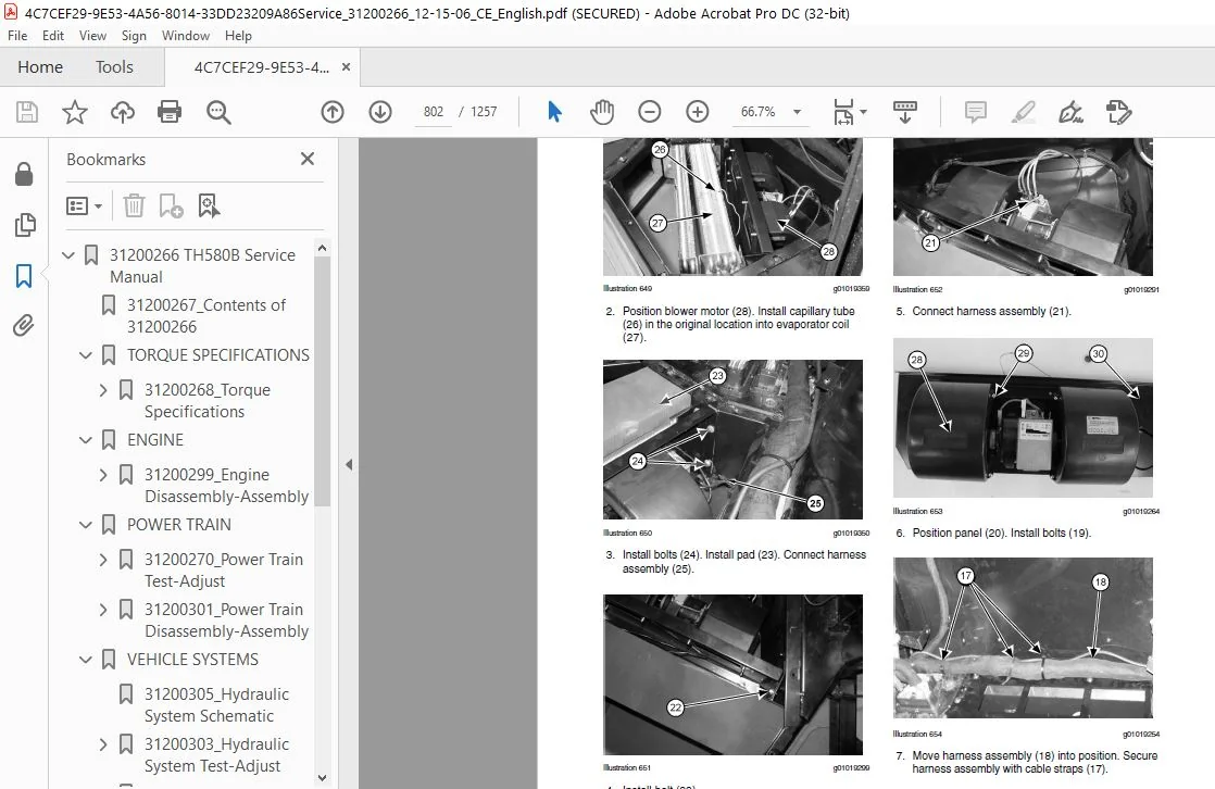
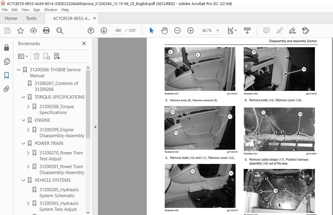
Refrigerant Condenser - Remove and Install.................................................... 42
Removal Procedure......................................................................... 42
Installation Procedure.................................................................... 43
Refrigerant Compressor - Remove and Install................................................... 44
Removal Procedure......................................................................... 44
Installation Procedure.................................................................... 44
Engine Mount (Front) - Remove................................................................. 45
Removal Procedure......................................................................... 45
Engine Mount (Front) - Install................................................................ 46
Installation Procedure.................................................................... 46
Engine Mount (Rear) - Remove.................................................................. 47
Removal Procedure......................................................................... 47
Engine Mount (Rear) - Install................................................................. 48
Installation Procedure.................................................................... 48
Engine Enclosure - Remove and Install......................................................... 48
Removal Procedure......................................................................... 48
Installation Procedure.................................................................... 49
Engine - Remove............................................................................... 50
Removal Procedure......................................................................... 50
Engine - Install.............................................................................. 53
Installation Procedure.................................................................... 53
POWER TRAIN............................................................................................... 60
31200270_Power Train Test-Adjust...................................................................... 60
Table of Contents................................................................................. 4
Systems Operation Section......................................................................... 64
Graphic Color Codes........................................................................... 64
Introduction.................................................................................. 65
General Information........................................................................... 66
Location of Electrical Components............................................................. 67
Transmission Neutralizer Switch........................................................... 68
Parking Brake Switch...................................................................... 68
Service Brake Pressure Switch............................................................. 68
Transmission Direction Control Lever (Power Shuttle Transmission)......................... 69
Transmission Speed Selector (Powersynchro Transmission)................................... 69
Differential Lock Switch (if Equipped..................................................... 69
Transmission Oil Temperature Sensor....................................................... 69
Torque Converter Output Sensor for the Temperature of the Oil............................. 69
Engine Speed Sensor....................................................................... 69
Torque Converter Output Speed Sensor...................................................... 69
Transmission Intermediate Speed Sensors................................................... 70
Transmission Output Speed Sensor.......................................................... 70
Shift Rail Sensors........................................................................ 70
Electronic Control Module................................................................. 70
Modulating Valve for the Synchronizers.................................................... 70
Solenoid Valves........................................................................... 71
Transmission Neutralizer Override Switch.................................................. 71
Location of Hydraulic Components.............................................................. 71
Transmission Charge Pump.................................................................. 72
Torque Converter.......................................................................... 72
Hydraulic Oil Cooler...................................................................... 72
Electrical Input Components................................................................... 73
Sensors................................................................................... 73
Switches.................................................................................. 75
Transmission Control...................................................................... 76
Electronic Control Module..................................................................... 77
Inputs.................................................................................... 77
Outputs................................................................................... 77
Input/Output.............................................................................. 77
Electrical Output Components.................................................................. 81
Synchronizer Solenoids.................................................................... 82
Directional Solenoids..................................................................... 82
Instrument Cluster........................................................................ 82
Data Link..................................................................................... 83
CAT Data Link............................................................................. 83
CAN Data Link............................................................................. 83
Electrical Schematic.......................................................................... 83
Transmission Charge Pump...................................................................... 85
Modulating Valve (Transmission)............................................................... 85
Solenoid Valves (Transmission)................................................................ 85
Directional Solenoids..................................................................... 85
Speed or Synchronized Solenoids........................................................... 86
Torque Converter.............................................................................. 87
Transmission.................................................................................. 89
Clutch Operation.......................................................................... 92
Operation of the Synchronizers............................................................ 93
Synchronizer for the Third Speed and Fourth Speed......................................... 96
Limits.................................................................................... 98
Cooler (Hydraulic Oil)........................................................................ 99
Transmission Control (Shift Lever)............................................................ 99
Powersynchro Transmission................................................................. 100
Power Shuttle Transmission................................................................ 100
Transmission Power Flow....................................................................... 101
Examples of Power Flow Through the Transmission........................................... 103
Differential Lock Control (If Equipped)....................................................... 105
Front Axle and Rear Axle...................................................................... 107
Final Drives.............................................................................. 107
Hydraulic Schematic (Power Train System)...................................................... 109
Neutral (Power Shuttle Transmission)...................................................... 109
Neutral (Powersynchro Transmission)....................................................... 110
Neutral into First Gear (Start of shift).................................................. 111
Neutral Into First Gear (End of Shift) (FORWARD).......................................... 112
Configuration Parameters...................................................................... 114
Testing and Adjusting Section..................................................................... 116
Transmission Shift Rail - Calibrate........................................................... 116
Machine Preparation....................................................................... 116
Transmission Fill - Calibrate................................................................. 123
Machine Preparation....................................................................... 123
Torque Converter Stall - Test................................................................. 130
Introduction.............................................................................. 130
Required Tools............................................................................ 130
Test Procedure............................................................................ 130
Measurement of the Stall Speed............................................................ 131
Transmission Pressures - Test and Adjust...................................................... 131
Pressure Test Points for the Powersynchro Transmission.................................... 132
Pressure Test Points for the Power Shuttle Transmission................................... 133
Oil Level Check........................................................................... 133
Torque Converter Inlet Pressure........................................................... 133
Regulated Pump Pressure................................................................... 134
Operating Pressures of Clutches and Synchronizers......................................... 135
Differential Pinion Bearing - Adjust.......................................................... 136
Introduction.............................................................................. 136
Required Tools............................................................................ 136
Procedure................................................................................. 137
Differential Backlash and Bearings - Adjust................................................... 142
Front Axle Differential................................................................... 142
Rear Axle Differential.................................................................... 145
Tooth Contact Pattern..................................................................... 146
Axle Housing and Bearing Preload - Adjust..................................................... 148
Introduction.............................................................................. 148
Adjustment Procedure...................................................................... 149
31200301_Power Train Disassembly-Assembly............................................................. 154
Table of Contents................................................................................. 4
Disassembly and Assembly Section.................................................................. 158
Transmission Control (Select Lever) - Remove and Install...................................... 158
Removal Procedure......................................................................... 158
Installation Procedure.................................................................... 160
Drive Shaft (Front) - Remove and Install...................................................... 162
Removal Procedure......................................................................... 162
Installation Procedure.................................................................... 162
Drive Shaft (Rear) - Remove and Install....................................................... 163
Removal Procedure......................................................................... 163
Installation Procedure.................................................................... 163
Transmission and Torque Converter - Remove.................................................... 163
Removal Procedure......................................................................... 163
Transmission - Disassemble.................................................................... 168
Disassembly Procedure..................................................................... 168
Transmission - Assemble....................................................................... 198
Assembly Procedure........................................................................ 198
Transmission and Torque Converter - Install................................................... 230
Installation Procedure.................................................................... 230
Drive and Steering Axle (Front) - Remove...................................................... 235
Removal Procedure......................................................................... 235
Drive and Steering Axle (Front) - Install..................................................... 237
Installation Procedure.................................................................... 237
Drive and Steering Axle (Rear) - Remove....................................................... 238
Removal Procedure......................................................................... 238
Drive and Steering Axle (Rear) - Install...................................................... 241
Installation Procedure.................................................................... 241
Tie Rod (Steering) - Remove and Install....................................................... 243
Removal Procedure......................................................................... 243
Installation procedure.................................................................... 244
Steering Cylinder - Remove and Install........................................................ 245
Removal Procedure......................................................................... 245
Installation Procedure.................................................................... 246
Final Drive Planetary - Remove................................................................ 247
Removal Procedure......................................................................... 247
Final Drive Planetary Disassemble............................................................. 248
Disassembly Procedure..................................................................... 248
Final Drive Planetary Assemble................................................................ 248
Assembly Procedure........................................................................ 248
Final Drive Planetary - Install............................................................... 249
Installation Procedure.................................................................... 249
Axle Housing and Flange - Remove.............................................................. 249
Removal Procedure......................................................................... 249
Axle Housing and Flange - Disassemble......................................................... 252
Disassembly Procedure..................................................................... 252
Axle Housing and Flange - Assemble............................................................ 254
Assembly Procedure........................................................................ 254
Axle Housing and Flange Install............................................................... 257
Installation Procedure.................................................................... 257
Axle Shaft - Remove and Install............................................................... 260
Removal Procedure......................................................................... 260
Installation Procedure.................................................................... 261
Axle Housing (Service Brakes, Differential and Bevel Gear) (Front) - Remove................... 262
Removal Procedure......................................................................... 262
Axle Housing (Service Brakes, Differential and Bevel Gear) (Front) - Disassemble.............. 263
Disassembly Procedure..................................................................... 263
Axle Housing (Service Brakes, Differential and Bevel Gear) (Front) -Assemble.................. 270
Assembly Procedure........................................................................ 270
Axle Housing (Service Brakes, Differential and Bevel Gear) (Front) - Install.................. 281
Installation Procedure.................................................................... 281
Axle Housing (Differential and Bevel Gear) (Rear) - Remove.................................... 282
Removal Procedure......................................................................... 282
Axle Housing (Differential and Bevel Gear) (Rear) - Disassemble............................... 283
Disassembly Procedure..................................................................... 283
Axle Housing (Differential and Bevel Gear) (Rear) - Assemble.................................. 287
Assembly Procedure........................................................................ 287
Axle Housing (Differential and Bevel Gear) (Rear) - Install................................... 294
Installation Procedure.................................................................... 294
Brake Cylinder (Master) Remove and Install.................................................... 295
Removal Procedure......................................................................... 295
Installation Procedure.................................................................... 296
Parking Brake Control -Remove and Install..................................................... 297
Removal Procedure......................................................................... 297
Installation Procedure........................................................................ 299
Parking Brake - Remove........................................................................ 300
Removal Procedure......................................................................... 300
Parking Brake - Disassemble................................................................... 300
Disassembly Procedure..................................................................... 300
Parking Brake - Assemble...................................................................... 302
Assembly Procedure........................................................................ 302
Parking Brake - Install....................................................................... 304
Installation Procedure.................................................................... 304
Tire and Rim - Remove and Install............................................................. 305
Removal Procedure......................................................................... 305
Installation Procedure.................................................................... 306
VEHICLE SYSTEMS........................................................................................... 312
31200305_Hydraulic System Schematic................................................................... 312
31200303_Hydraulic System Test-Adjust................................................................. 314
Table of Contents................................................................................. 4
Systems Operation Section......................................................................... 318
Graphic Color Codes........................................................................... 318
Introduction.................................................................................. 319
General Information........................................................................... 320
Main Control Valve Group (Implement)...................................................... 320
Stabilizer Control Valve Gp (If Equipped)................................................. 321
Machine ECM............................................................................... 322
Electronic Joystick....................................................................... 323
Operator Switches......................................................................... 324
Piston Pump (Implement and Steering)...................................................... 324
Hydraulic Oil Tank........................................................................ 324
Hydraulic Oil Filter...................................................................... 325
System Operation.......................................................................... 325
Load Independent Flow Division (LIFD)..................................................... 326
Location of Electrical Components............................................................. 327
Switch (Lockout Control).................................................................. 327
Joystick Control.......................................................................... 327
Switch (Continuous Auxiliary Flow)........................................................ 329
Switch (Quick Coupler).................................................................... 329
Switch (Right Stabilizer)................................................................. 330
Switch (Left Stabilizer).................................................................. 330
Switch (Frame Level)...................................................................... 330
Pressure Switches (Stabilizer)............................................................ 330
Switch (Fully Lowered Boom)............................................................... 331
Switch (Critical Angle)................................................................... 331
Switch (Fully Retracted Boom)............................................................. 331
Machine (ECM)............................................................................. 331
Main Control Valve (Implement)............................................................ 332
Stabilizer Control Valve Gp (If Equipped)................................................. 332
Solenoids (Frame Level)................................................................... 332
Solenoid (Diverter Valve)................................................................. 333
Solenoid (Diverter Valve for Auxiliary 1)................................................. 333
Relay (Frame Level)....................................................................... 333
Relays (Diverter Valve)................................................................... 333
Relays (Quick Coupler).................................................................... 334
Location of Hydraulic Components.............................................................. 334
Hydraulic Tank............................................................................ 334
Piston Pump (Implement and Steering)...................................................... 334
Compensator Valve......................................................................... 335
Main Control Valve (Implement)............................................................ 335
Inlet Manifold............................................................................ 335
Outlet Manifold........................................................................... 336
Boom Cylinder............................................................................. 46
Load Control Valve (Boom Cylinder) (Lock)................................................. 337
Telescoping Cylinder...................................................................... 47
Load Control Valve (Telescoping Cylinder) (Lock).......................................... 337
Tilt Cylinder............................................................................. 337
Load Control Valve (Tilt Cylinder) (Lock)................................................. 338
Compensating Cylinders.................................................................... 338
Diverter Valve............................................................................ 48
Quick Coupler Cylinder.................................................................... 338
Frame Leveling Cylinder................................................................... 339
Lock Valve (Frame Leveling Cylinder)...................................................... 339
Control Valve Gp (Stabilizer)............................................................. 339
Stabilizer Cylinders...................................................................... 339
Load Control Valve (Stabilizer Cylinders) (Lock).......................................... 340
Lowering Control Pump (Manual)............................................................ 340
Electrical Input Components................................................................... 340
Switches.................................................................................. 341
Electronic Control Module..................................................................... 343
Inputs.................................................................................... 343
Outputs................................................................................... 343
Data Links................................................................................ 343
Input/Output.............................................................................. 343
Electrical Output Components.................................................................. 347
Relays.................................................................................... 348
Solenoids................................................................................. 348
Electrical Function Requirements.............................................................. 349
Transmission Neutralizer.................................................................. 349
More Electrical Function Requirements..................................................... 350
Steering.................................................................................. 350
The Neutral Start Is Disabled............................................................. 350
Stabilizer Raise/Lower (if equipped) is Disabled.......................................... 350
Boom Raise/Lower Is Disabled.............................................................. 351
The Boom Extend/Retract Is Disabled....................................................... 351
Disable The Rackback And Dump............................................................. 351
The Frame Level (if equipped) is Disabled................................................. 351
Disable the Quick Coupler................................................................. 351
Miscellaneous............................................................................. 352
Electrical Schematic.......................................................................... 352
Piston Pump (Implement and Steering).......................................................... 354
Piston Pump............................................................................... 354
Compensator Valve......................................................................... 355
Low Pressure Standby...................................................................... 356
Upstroke.................................................................................. 357
Constant Flow............................................................................. 358
Destroke.................................................................................. 359
High Pressure Stall....................................................................... 361
Main Control Valve (Implement)................................................................ 362
Manifold Valve (Inlet)........................................................................ 364
Check and Relief Valves....................................................................... 365
Manifold Valve (Outlet)....................................................................... 366
Lowering Control Pump (Electric) (If equipped)................................................ 367
Electric Lowering Control Pump (If Equipped).............................................. 367
Lowering Control Pump (Manual)................................................................ 369
Accumulator................................................................................... 373
Boom Hydraulic System......................................................................... 374
Control valve (implement)................................................................. 374
Telescoping System............................................................................ 383
Valve for the Telescoping Cylinder in the HOLD Position................................... 383
Valve for the Telescoping Cylinder in the EXTEND Position................................. 385
Valve for the Telescoping Cylinder in the RETRACT Position................................ 386
Auxiliary Hydraulic System.................................................................... 388
Introduction.............................................................................. 388
Auxiliary Control (Combined Circuit)...................................................... 389
Relief Valves and Makeup Valves........................................................... 394
Compensating System........................................................................... 395
Frame Leveling System......................................................................... 399
Stabilizer System............................................................................. 402
Hydraulic System Schematic.................................................................... 407
All Implements In HOLD.................................................................... 407
Configuration Parameters.................................................................. 412
Testing and Adjusting Section..................................................................... 414
Troubleshooting............................................................................... 414
Machine Preparation for Troubleshooting................................................... 414
General Troubleshooting Information........................................................... 414
Visual Inspection............................................................................. 415
Operational Checks............................................................................ 415
Hydraulic System Troubleshooting.............................................................. 415
Operation Checks.......................................................................... 416
Troubleshooting Problem List.............................................................. 416
Troubleshooting Probable Causes........................................................... 416
Testing and Adjusting......................................................................... 418
Main Control Valve (Implement) - Calibrate.................................................... 437
Programmable Hydraulic System (PHS) Valve Calibrations.................................... 437
Hydraulic System Pressure - Release........................................................... 446
Relieving Pressure in the Hydraulic System................................................ 447
Lock Valve Locations...................................................................... 447
Relieving Pressure from the Lock Valves................................................... 448
Verifying the Correct Setting of the Load Control Valves.................................. 451
Accumulator - Test and Charge................................................................. 452
Testing and Charging the Pilot System Accumulators........................................ 452
Pilot Pressure (Pressure Reducing Valve) - Test and Adjust.................................... 453
Pilot Pressure Test....................................................................... 454
Pressure Reducing Valve Adjustment........................................................ 455
Adjustment Procedure...................................................................... 455
Relief Valve (Implement) - Test and Adjust.................................................... 456
Auxiliary Pressure Test (Port A and Port B)............................................... 456
Auxiliary Relief Valve Adjustments........................................................ 458
Pressure Adjustment for Engaging the Quick Coupler........................................ 458
Hydraulic Oil Contamination - Test............................................................ 458
Hydraulic Oil Contamination............................................................... 458
Flushing the Sampling Valve............................................................... 459
Obtaining the Sample...................................................................... 459
Boom Chain - Clean/Inspect/ Lubricate......................................................... 460
Boom Chains............................................................................... 460
31200273_Steering System Test-Adjust.................................................................. 466
Table of Contents................................................................................. 4
Systems Operation Section......................................................................... 470
Graphic Color Codes........................................................................... 470
General Information........................................................................... 471
Steering Arrangement...................................................................... 471
Introduction.................................................................................. 473
Location of Electrical Components............................................................. 474
Selector Switch for the Steering Mode..................................................... 350
Position Sensors.......................................................................... 474
Electronic Control Module................................................................. 475
Solenoid for Crab Steer................................................................... 475
Solenoid for Circle Steer................................................................. 475
Relay (Crab Steer)........................................................................ 475
Relay (Circle Steer)...................................................................... 476
Location of Hydraulic Components.............................................................. 476
Steering Wheel............................................................................ 476
Metering Pump............................................................................. 477
Piston Pump............................................................................... 477
Line for the Signal Limiter Valve for the Steering........................................ 477
Priority Valve............................................................................ 34
Control Valve (Steering).................................................................. 478
Steering Cylinders........................................................................ 478
Hydraulic Tank............................................................................ 478
Hydraulic Tank Breather................................................................... 478
Hydraulic Oil Level Indicator............................................................. 479
Hydraulic Oil Drain Plugs................................................................. 479
Electrical Input Components................................................................... 479
Steering Mode Switch...................................................................... 479
Position Sensor........................................................................... 480
Electronic Control Module..................................................................... 480
Electrical Output Components.................................................................. 481
Relays.................................................................................... 481
Instrument Cluster........................................................................ 481
Data Link..................................................................................... 481
CAT Data Link............................................................................. 481
CAN Data Link............................................................................. 482
Electrical Schematic.......................................................................... 482
Inlet Manifold................................................................................ 482
Steering Priority Valve................................................................... 483
Screens (75 and 100 Micron)............................................................... 483
Flow Control Valve (Dump valve for the load sensing oil).................................. 483
Relief Valve (Load sensing oil)........................................................... 483
Check Valve............................................................................... 483
Steering Not Activated.................................................................... 484
Steering Activated........................................................................ 485
Steering System............................................................................... 486
Steering Control System................................................................... 486
Steering in Neutral....................................................................... 487
Right Turn in Two-Wheel Steer Mode........................................................ 489
Left Turn in Circle Steer Mode............................................................ 254
Left Turn in Crab Steer Mode.............................................................. 493
Hydraulic Schematic (Steering System)......................................................... 495
Piston Pump (Implement and Steering).......................................................... 496
Piston Pump............................................................................... 496
Compensator Valve......................................................................... 497
Low Pressure Standby...................................................................... 498
Upstroke.................................................................................. 499
Constant Flow............................................................................. 500
Destroke.................................................................................. 501
High Pressure Stall....................................................................... 503
Solenoid Valve (Steering Mode Selector)....................................................... 504
Solenoid Valve............................................................................ 53
Metering Pump (Steering)...................................................................... 504
Hold...................................................................................... 506
Right Turn................................................................................ 507
Position Sensor (Steering).................................................................... 509
Configuration Parameters...................................................................... 510
Testing and Adjusting Section..................................................................... 512
Hydraulic Oil Contamination - Test............................................................ 512
Hydraulic Oil Contamination............................................................... 512
Flushing the Sampling Valve............................................................... 512
Obtaining the Sample...................................................................... 512
Pump Flow - Test.............................................................................. 513
Pump Flow................................................................................. 513
Test On The Machine....................................................................... 513
Test On The Bench......................................................................... 514
Steering System Pressures - Test and Adjust................................................... 514
Steering System Pressure Tests and Adjustments............................................ 514
Steering Pressure Test.................................................................... 515
Steering Pressure Adjustment.............................................................. 515
Margin Pressure Test...................................................................... 516
Margin Pressure Adjustment................................................................ 517
Test for the Relief Valve (Load Sensing Oil).............................................. 517
Adjustment of the Relief Valve (Load Sensing Oil)......................................... 518
Test for Pressure Compensator............................................................. 518
Pressure Compensator Adjustment........................................................... 519
Low Pressure Standby Test................................................................. 519
Low Pressure Standby Adjustment........................................................... 520
Steering System - Purge....................................................................... 521
Purging the Steering System............................................................... 521
Solenoid Valve (Steering Mode Selector) - Test................................................ 521
The Solenoid's for the Steering Modes..................................................... 521
Position Sensor (Steering) - Adjust........................................................... 522
Position Sensor........................................................................... 522
Wheel Alignment - Check and Adjust............................................................ 524
Checking the Wheel Alignment With Wheels In Place......................................... 525
Adjusting the Wheel Alignment............................................................. 525
Adjusting the Steering Angle.............................................................. 526
General Information Table..................................................................... 527
31200274_Braking System Test-Adjust................................................................... 532
Table of Contents................................................................................. 4
Systems Operation Section......................................................................... 158
Graphic Color Codes........................................................................... 536
Introduction.................................................................................. 537
General Information........................................................................... 538
Brake Packs............................................................................... 538
Brake Pedal............................................................................... 538
Brake Cylinder............................................................................ 538
Service Brake Pressure Switch............................................................. 539
Parking Brake Lever....................................................................... 539
Location of Electrical Components............................................................. 539
Parking Brake Switch...................................................................... 539
Service Brake Pressure Switch............................................................. 539
Stoplight Switch.......................................................................... 539
Location of Components (Braking).............................................................. 540
Parking Brake Lever....................................................................... 540
Parking Brake Actuator.................................................................... 540
Service Brake Pedal....................................................................... 540
Brake Cylinder............................................................................ 541
Service Brake Discs....................................................................... 541
Service Brake................................................................................. 541
Service Brake............................................................................. 541
The Service Brake System with the Brakes Disengaged....................................... 543
The Service Brake System with the Brakes Engaged.......................................... 544
Parking Brake................................................................................. 545
Engaging the Parking Brake................................................................ 545
Disengaging the Parking Brake............................................................. 546
Brake Cylinder (Master)....................................................................... 322
Brake Cylinder with the Brakes Disengaged................................................. 548
Brake Cylinder with the Brakes Engaged.................................................... 550
Hydraulic Schematic (Braking System).......................................................... 552
Configuration Parameters...................................................................... 553
Electrical Function Requirements.............................................................. 554
Transmission Neutralizer.................................................................. 554
System Voltage............................................................................ 554
Shuttle Shift for the Power Shuttle Transmission.......................................... 554
Shift Lever (Cat Data Link) for Powersynchro Transmission................................. 554
Rear Axle Lock (if equipped).............................................................. 470
Machine Security System................................................................... 470
Parking Brake............................................................................. 554
Service Brake Pressure Switch for the Transmission Neutralizer............................ 555
More Electrical Function Requirements......................................................... 555
Steering.................................................................................. 555
The Neutral Start Is Disabled............................................................. 471
Stabilizer Raise/Lower (if equipped) is Disabled.......................................... 556
Boom Raise/Lower Is Disabled.............................................................. 556
The Boom Extend/Retract Is Disabled....................................................... 556
Disable The Rackback And Dump............................................................. 556
The Frame Level (if equipped) is Disabled................................................. 557
Disable the Quick Coupler................................................................. 557
Miscellaneous............................................................................. 557
Testing and Adjusting Section..................................................................... 558
Testing and Adjusting Service Brake - Test.................................................... 558
Holding Ability Test for the Service Brakes............................................... 558
Stopping Performance Test for the Service Brakes.......................................... 558
Service Brake Control - Check and Adjust...................................................... 558
Adjusting the Brake Pedal Linkage......................................................... 558
Service Brake Discs - Check................................................................... 560
Checking the Wear on the Service Brake Discs.............................................. 560
Procedure for Checking the Wear........................................................... 560
Service Brake Air - Purge..................................................................... 561
Purging Air from the Braking System....................................................... 561
Parking Brake - Test.......................................................................... 562
Holding Ability Test for the Parking Brake................................................ 562
Parking Brake Control - Check and Adjust...................................................... 563
Adjusting the Parking Brake Control Cable................................................. 563
31200307_Machine Components Specifications............................................................ 570
Table of Contents................................................................................. 4
Specifications Section............................................................................ 473
Hydraulic Tank................................................................................ 574
Piston Pump (Implement and Steering).......................................................... 557
Solenoid Valve (Pilot Selector)............................................................... 577
Main Control Valve (Implement)................................................................ 578
Boom.......................................................................................... 580
Boom Cylinder................................................................................. 478
Load Control Valve (Boom Cylinder) (Lock)..................................................... 584
Compensating Cylinder......................................................................... 584
Telescoping Cylinder.......................................................................... 586
Load Control Valve (Telescoping Cylinder) (Lock).............................................. 327
Tilt Cylinder................................................................................. 588
Load Control Valve (Tilt Cylinder) (Lock)..................................................... 589
Diverter Valve................................................................................ 589
Diverter Valve................................................................................ 590
Towing Hitch.................................................................................. 591
Frame Leveling Cylinder....................................................................... 592
Load Control Valve (Frame Leveling Cylinder) (Lock)........................................... 593
Control Valve (Stabilizer).................................................................... 42
Stabilizer Cylinder........................................................................... 595
Metering Pump (Steering)...................................................................... 596
Solenoid Valve (Steering Mode Selector)....................................................... 596
Position Sensor (Steering).................................................................... 597
Position Sensor (Steering).................................................................... 597
Flexible Coupling Drive....................................................................... 598
Transmission.................................................................................. 599
Transmission.................................................................................. 601
Position Sensor (Transmission)................................................................ 603
Oil Filter.................................................................................... 604
Hydraulic Oil Cooler.......................................................................... 606
Drive Shaft................................................................................... 607
Drive and Steering Axle (Front)............................................................... 608
Drive and Steering Axle Gp, with Steering Sensor.......................................... 608
Drive and Steering Axle (Rear)................................................................ 609
231 -0710 Drive and Steering Axle Gp, without Steering Sensor................................. 609
231 -0709 Drive and Steering Axle Gp, with Steering Sensor................................ 610
Differential and Bevel Gear Group............................................................. 611
Axle Housing and Flange Group................................................................. 612
Final Drive Planetary Group................................................................... 613
Axle Housing Group (Differential and Brake Cylinder).......................................... 614
253-4990 Axle Housing Gp with a Locking Differential...................................... 614
253-4985 Axle Housing Gp without a Locking Differential................................... 615
Brake Cylinder (Master)....................................................................... 616
Parking Brake Control......................................................................... 617
Parking Brake................................................................................. 618
Fender........................................................................................ 618
Wheel (Tire and Rim).......................................................................... 619
Fuel Tank..................................................................................... 620
Engine Enclosure.............................................................................. 621
Engine and Transmission Mounting.............................................................. 623
Air Cleaner................................................................................... 624
Engine Oil Drain.............................................................................. 626
Muffler....................................................................................... 627
Suction Fan................................................................................... 628
Battery....................................................................................... 629
Alternator.................................................................................... 630
Coolant Lines Group........................................................................... 631
Coolant Recovery Group........................................................................ 632
Cab........................................................................................... 634
Latch Adjustment.......................................................................... 634
Cab Mounting.................................................................................. 635
Cab Door...................................................................................... 636
Access Door................................................................................... 638
Joystick Control.............................................................................. 639
Joystick Control.............................................................................. 640
Steering Wheel and Column..................................................................... 641
Window Wiper and Wiper Motor.................................................................. 642
Window Washer Tank............................................................................ 643
Rear View Mirror.............................................................................. 644
Carriage Cylinder (Rotate).................................................................... 645
Carriage Cylinder (Sideshift)................................................................. 646
Hydraulic Cylinder (Multipurpose Bucket)...................................................... 647
31200309_Machine Systems Disassembly-Assembly......................................................... 652
Table of Contents................................................................................. 4
Disassembly and Assembly Section.................................................................. 656
Hydraulic System Pressure - Release........................................................... 656
Release Procedure......................................................................... 656
Bottom Guard - Remove and Install............................................................. 657
Removal Procedure......................................................................... 657
Installation Procedure.................................................................... 657
Hydraulic Tank - Remove and Install........................................................... 658
Removal Procedure......................................................................... 658
Installation Procedure.................................................................... 659
Piston Pump (Implement and Steering) - Remove................................................. 163
Removal Procedure......................................................................... 660
Piston Pump (Implement and Steering) - Disassemble............................................ 662
Disassembly Procedure..................................................................... 662
Piston Pump (Implement and Steering) - Assemble............................................... 669
Assembly Procedure........................................................................ 669
Piston Pump (Implement and Steering) - Install................................................ 677
Installation Procedure.................................................................... 677
Main Control Valve (Implement) - Remove....................................................... 678
Removal Procedure......................................................................... 678
Bank Valve (Implement) - Disassemble.......................................................... 680
Disassembly Procedure..................................................................... 680
Bank Valve (Implement) - Assemble............................................................. 687
Assembly Procedure........................................................................ 687
Main Control Valve (Implement) - Install...................................................... 694
Installation Procedure.................................................................... 694
Tilt Cylinder - Remove and Install............................................................ 696
Removal Procedure......................................................................... 696
Disassembly and Assembly Information...................................................... 698
Installation Procedure.................................................................... 699
Control Valve (Compensating Cylinder) - Remove and Install.................................... 701
Removal Procedure......................................................................... 701
Installation Procedure.................................................................... 701
Compensating Cylinder - Remove and Install.................................................... 702
Removal Procedure......................................................................... 702
Disassembly and Assembly Information...................................................... 704
Installation Procedure.................................................................... 705
Load Control Valve (Telescoping Cylinder) - Remove and Install................................ 707
Removal Procedure......................................................................... 707
Installation Procedure.................................................................... 707
Telescoping Cylinder - Remove and Install..................................................... 708
Removal Procedure......................................................................... 708
Disassembly and Assembly Information...................................................... 710
Installation Procedure.................................................................... 711
Diverter Valve (Boom Head) - Remove and Install............................................... 713
Removal Procedure......................................................................... 713
Installation Procedure.................................................................... 713
Load Control Valve (Boom Cylinder) - Remove and Install....................................... 349
Installation Procedure.................................................................... 715
Boom Cylinder - Remove and Install............................................................ 715
Removal Procedure......................................................................... 351
Disassembly and Assembly Information...................................................... 717
Installation Procedure.................................................................... 718
Coupler Cylinder - Remove and Install......................................................... 720
Removal Procedure......................................................................... 720
Installation Procedure.................................................................... 721
Quick Coupler - Remove........................................................................ 722
Removal Procedure......................................................................... 722
Quick Coupler - Install....................................................................... 723
Installation Procedure.................................................................... 723
Removal Procedure......................................................................... 725
Boom - Install................................................................................ 734
Installation Procedure.................................................................... 734
Hydraulic Oil Cooler (Transmission and Hydraulic System) - Remove and Install................. 743
Removal Procedure......................................................................... 743
Installation Procedure.................................................................... 744
Control Valve (Stabilizer) - Remove........................................................... 744
Removal Procedure......................................................................... 744
Bank Valve (Stabilizer) - Disassemble......................................................... 746
Disassembly Procedure..................................................................... 746
Bank Valve (Stabilizer) - Assemble............................................................ 748
Assembly Procedure........................................................................ 748
Control Valve (Stabilizer) -Install........................................................... 750
Installation Procedure.................................................................... 750
Load Control Valve (Stabilizer Cylinder) - Remove and Install................................. 399
Removal Procedure......................................................................... 751
Installation Procedure.................................................................... 752
Stabilizer Cylinder - Remove and Install...................................................... 753
Removal Procedure......................................................................... 753
Disassembly and Assembly Information...................................................... 754
Installation Procedure.................................................................... 756
Stabilizer - Remove........................................................................... 758
Removal Procedure......................................................................... 758
Stabilizer - Install.......................................................................... 759
Installation Procedure.................................................................... 759
Solenoid Valve (Frame Leveling) - Remove and Install.......................................... 761
Removal Procedure......................................................................... 761
Installation Procedure.................................................................... 761
Load Control Valve (Frame Leveling Cylinder) - Remove and Install............................. 762
Removal Procedure......................................................................... 762
Installation Procedure.................................................................... 763
Frame Leveling Cylinder - Remove and Install.................................................. 765
Removal Procedure......................................................................... 765
Disassembly and Assembly Information...................................................... 766
Installation Procedure.................................................................... 769
Fuel Tank - Remove and Install................................................................ 770
Removal Procedure......................................................................... 770
Installation Procedure.................................................................... 772
Steering Wheel - Remove and Install........................................................... 774
Installation Procedure.................................................................... 774
Steering Column - Remove...................................................................... 775
Removal Procedure......................................................................... 775
Steering Column - Install..................................................................... 778
Installation Procedure.................................................................... 778
Solenoid Valve (Steering Mode Selector) - Remove and Install.................................. 780
Removal Procedure......................................................................... 780
Installation Procedure.................................................................... 781
Metering Pump (Steering) - Remove............................................................. 782
Removal Procedure......................................................................... 782
Metering Pump (Steering) - Install............................................................ 785
Installation Procedure.................................................................... 785
Window Wiper and Wiper Motor (Front) - Remove and Install..................................... 787
Removal Procedure......................................................................... 787
Installation Procedure.................................................................... 788
Window Wiper and Wiper Motor (Roof) - Remove and Install...................................... 789
Removal Procedure......................................................................... 789
Installation procedure.................................................................... 790
Joystick Control - Remove and Install......................................................... 791
Removal Procedure......................................................................... 791
Installation Procedure.................................................................... 792
Seat - Remove and Install..................................................................... 793
Removal Procedure......................................................................... 793
Installation Procedure.................................................................... 793
Cab Heater - Remove........................................................................... 794
Removal Procedure......................................................................... 794
Removal Procedure......................................................................... 796
Installation Procedure.................................................................... 797
Evaporator Coil - Remove and Install.......................................................... 797
Removal Procedure......................................................................... 797
Installation procedure.................................................................... 798
Blower Motor (Air Conditioner and Heater) - Remove and Install................................ 799
Removal Procedure......................................................................... 799
Installation procedure.................................................................... 801
Cab Heater - Install.......................................................................... 804
Installation Procedure.................................................................... 804
Cab - Remove.................................................................................. 807
Removal Procedure......................................................................... 807
Cab - Install................................................................................. 810
Installation Procedure.................................................................... 810
Fender - Remove and Install................................................................... 813
Removal Procedure......................................................................... 813
Installation Procedure.................................................................... 813
Counterweight - Remove and Install............................................................ 814
Removal Procedure......................................................................... 814
Installation Procedure.................................................................... 814
ELECTRICAL SYSTEMS........................................................................................ 820
31200312_Electrical System Schematic.................................................................. 820
31200279_Electronic Control System, Hydrostatic Transmission Troubleshooting Test-Adjust.............. 824
Table of Contents................................................................................. 826
Introduction...................................................................................... 830
General Information........................................................................... 830
Service Tools................................................................................. 830
Connector Locations........................................................................... 831
Connector Contact Numbers................................................................. 831
Diagnostic Capabilities....................................................................... 832
Monitoring System/Instrument Cluster...................................................... 832
The Caterpillar Electronic Technician (ET)................................................ 833
Logged Event Codes........................................................................ 834
Status Groups For The Electronic Technician............................................... 835
Machine Preparation for Troubleshooting....................................................... 835
General Troubleshooting Information........................................................... 836
Visual Inspection............................................................................. 836
Operational Checks............................................................................ 836
Operational Checks (Braking System)....................................................... 836
Operational Checks (Steering System)...................................................... 837
Operational Checks (Power Train).......................................................... 837
Operational Checks (Hydraulic System)..................................................... 837
Event Code List............................................................................... 839
Warning Levels............................................................................ 839
Indications and System Response........................................................... 839
Troubleshooting........................................................................... 840
Telehandler Event Code List............................................................... 840
Symptom Procedures................................................................................ 842
Steering System............................................................................... 842
Troubleshooting The Steering System....................................................... 842
Brake System.................................................................................. 843
Troubleshooting The Brake System.......................................................... 843
Troubleshooting The Parking Brake......................................................... 844
Transmission.................................................................................. 844
Troubleshooting The Transmission System................................................... 844
Hydraulic System.............................................................................. 846
Troubleshooting The Hydraulic System...................................................... 846
Torque Converter.............................................................................. 848
Troubleshooting The Torque Converter...................................................... 848
Differential and Final Drive.................................................................. 849
The Differential And The Final Drive Troubleshooting...................................... 849
Diagnostic Code Procedures........................................................................ 852
Diagnostic Code List.......................................................................... 852
Module Identifier (MID)................................................................... 852
Component Identifier (CID)................................................................ 852
Failure Mode Identifier (FMI)............................................................. 854
Using the Operator Monitor to Determine Diagnostic Codes...................................... 856
Using Caterpillar Electronic Technician to Determine Diagnostic Codes......................... 856
Active Diagnostic Codes................................................................... 857
Logged Diagnostic Codes................................................................... 858
MID 039 - CID 0041 - FMI 03................................................................... 859
MID 039 - CID 0041 - FMI 04................................................................... 860
MID 039 - CID 0070 - FMI 03................................................................... 861
MID 039 - CID 0070 - FMI 04................................................................... 863
MID 039 - CID 0096 - FMI 03................................................................... 864
MID 039 - CID 0096 - FMI 04................................................................... 865
MID 039 - CID0 110 - FMI 03................................................................... 866
MID 039 - CID 0110 - FMI 04................................................................... 867
MID 039 - CID 0177 - FMI 03................................................................... 868
MID 039 - CID 0177 - FMI 04................................................................... 870
MID 039 - CID 0191 - FMI 02................................................................... 870
MID 039 - CID 0246 - FMI 12................................................................... 872
MID 039 - CID 0262 - FMI 03................................................................... 873
MID 039 - CID 0262 - FMI 04................................................................... 874
MID 039 - CID 0271 - FMI 03................................................................... 875
MID 039 - CID 0271 - FMI 04................................................................... 876
MID 039 - CID 0271 - FMI 05................................................................... 877
MID 039 - CID 0368 - FMI 03................................................................... 879
MID 039 - CID 0368 - FMI 04................................................................... 880
MID 039 - CID 0444 - FMI 03................................................................... 881
MID 039 - CID 0444 - FMI 04................................................................... 882
MID 039 - CID 0444 - FMI 05................................................................... 883
MID 039 - CID 0489 - FMI 02................................................................... 885
MID 039 - CID 0489 - FMI 04................................................................... 887
MID 039 - CID 0490 - FMI 02................................................................... 889
MID 039 - CID 0590 - FMI 02................................................................... 892
MID 039 - CID 0590 - FMI 09................................................................... 894
MID 039 - CID 0590 - FMI 12................................................................... 896
MID 039 - CID 0629 - FMI 04................................................................... 898
MID 039 - CID 0668 - FMI 02................................................................... 899
MID 039 - CID 0668 - FMI 09................................................................... 901
MID 039 - CID 0668 - FMI 12................................................................... 903
MID 039 - CID 0672 - FMI 02................................................................... 905
MID 039 - CID 0702 - FMI 02................................................................... 906
MID 039 - CID 0750 - FMI 02................................................................... 909
MID 039 - CID 0811 - FMI 09................................................................... 910
MID 039 - CID 0817 - FMI 04................................................................... 912
MID 039 - CID 0826 - FMI 03................................................................... 913
MID 039 - CID 0882 - FMI 05................................................................... 915
MID 039 - CID 0882 - FMI 06................................................................... 916
MID 039 - CID 1127 - FMI 00................................................................... 917
MID 039 - CID 1127 - FMI 01................................................................... 920
MID 039 - CID 1127 - FMI 02................................................................... 923
MID 039 - CID 1127 - FMI 08................................................................... 925
MID 039 - CID 1128 - FMI 00................................................................... 928
MID 039 - CID 1128 - FMI 01................................................................... 931
MID 039 - CID 1128 - FMI 02................................................................... 934
MID 039 - CID 1128 - FMI 08................................................................... 937
MID 039 - CID 1138 - FMI 05................................................................... 940
MID 039 - CID 1138 - FMI 06................................................................... 942
MID 039 - CID 1187 - FMI 04................................................................... 943
MID 039 - CID 1189 - FMI 00................................................................... 944
MID 039 - CID 1189 - FMI 01................................................................... 947
MID 039 - CID 1189 - FMI 02................................................................... 949
MID 039 - CID 1189 - FMI 08................................................................... 952
MID 039 - CID 1193 - FMI 05................................................................... 955
MID 039 - CID 1193 - FMI 06................................................................... 957
MID 039 - CID 1251 - FMI 08................................................................... 958
MID 039 - CID 1326 - FMI 02................................................................... 959
MID 039 - CID 1401 - FMI 03................................................................... 960
MID 039 - CID 1401 - FMI 05................................................................... 961
MID 039 - CID 1401 - FMI 06................................................................... 962
MID 039 - CID 1402 - FMI 03................................................................... 963
MID 039 - CID 1402 - FMI 06................................................................... 966
MID 039 - CID 1403 - FMI 03................................................................... 967
MID 039 - CID 1403 - FMI 05................................................................... 968
MID 039 - CID 1403 - FMI 06................................................................... 969
MID 039 - CID 1404 - FMI 03................................................................... 970
MID 039 - CID 1404 - FMI 05................................................................... 971
MID 039 - CID 1404 - FMI 06................................................................... 972
MID 039 - CID 1405 - FMI 03................................................................... 974
MID 039 - CID 1405 - FMI 05................................................................... 975
MID 039 - CID 1405 - FMI 06................................................................... 976
MID 039 - CID 1406 - FMI 03................................................................... 977
MID 039 - CID 1406 - FMI 05................................................................... 978
MID 039 - CID 1406 - FMI 06................................................................... 980
MID 039 - CID 1407 - FMI 03................................................................... 981
MID 039 - CID 1407 - FMI 05................................................................... 982
MID 039 - CID 1407 - FMI 06................................................................... 983
MID 039 - CID 1410 - FMI 05................................................................... 985
MID 039 - CID 1410 - FMI 06................................................................... 987
MID 039 - CID 1482 - FMI 03................................................................... 989
MID 039 - CID 1482 - FMI 04................................................................... 991
MID 039 - CID 1529 - FMI 02................................................................... 992
MID 039 - CID 1603 - FMI 09................................................................... 994
MID 039 - CID 1639 - FMI 02................................................................... 996
MID 039 - CID 1639 - FMI 09................................................................... 998
MID 039 - CID 1658 - FMI 00...................................................................1000
MID 039 - CID 1658 - FMI 01...................................................................1003
MID 039 - CID 1658 - FMI 02...................................................................1006
MID 039 - CID 1658 - FMI 08...................................................................1008
MID 039 - CID 1718 - FMI 02...................................................................1011
MID 039 - CID 1740 - FMI 03...................................................................1013
MID 039 - CID 1740 - FMI 04...................................................................1014
MID 039 - CID 1740 - FMI 05...................................................................1015
MID 039 - CID 1741 - FMI 03...................................................................1017
MID 039 - CID 1741 - FMI 04...................................................................1018
MID 039 - CID 1741 - FMI 05...................................................................1019
MID 039 - CID 1763 - FMI 02...................................................................1021
MID 039 - CID 1788 - FMI 02...................................................................1023
MID 039 - CID 1789 - FMI 02...................................................................1024
MID 039 - CID 1820 - FMI 05...................................................................1026
MID 039 - CID 1820 - FMI 06...................................................................1027
MID 039 - CID 1823 - FMI 03...................................................................1028
MID 039 - CID 1823 - FMI 04...................................................................1030
MID 039 - CID 1823 - FMI 08...................................................................1033
MID 039 - CID 1824 - FMI 03...................................................................1035
MID 039 - CID 1824 - FMI 04...................................................................1037
MID 039 - CID 1824 - FMI 08...................................................................1039
MID 039 - CID 1825 - FMI 03...................................................................1041
MID 039 - CID 1825 - FMI 04...................................................................1043
MID 039 - CID 1825 - FMI 08...................................................................1045
MID 039 - CID 1826 - FMI 00...................................................................1047
MID 039 - CID 1826 - FMI 01...................................................................1049
MID 039 - CID 1826 - FMI 02...................................................................1052
MID 039 - CID 1826 - FMI 08...................................................................1054
MID 039 - CID 1827 - FMI 13...................................................................1055
MID 039 - CID 1828 - FMI 02...................................................................1056
MID 039 - CID 1829 - FMI 02...................................................................1057
MID 039 - CID 1830 - FMI 02...................................................................1059
MID 039 - CID 1831 - FMI 05...................................................................1061
MID 039 - CID 1831 - FMI 06...................................................................1063
MID 039 - CID 1832 - FMI 02...................................................................1064
MID 039 - CID 1833 - FMI 02...................................................................1065
MID 039 - CID 1834 - FMI 03...................................................................1066
MID 039 - CID 1845 - FMI 02...................................................................1068
MID 039 - CID 1845 - FMI 05...................................................................1070
MID 039 - CID 1845 - FMI 06...................................................................1072
MID 039 - CID 1845 - FMI 09...................................................................1074
MID 039 - CID 1846 - FMI 02...................................................................1077
MID 039 - CID 1846 - FMI 05...................................................................1079
MID 039 - CID 1846 - FMI 06...................................................................1081
MID 039 - CID 1846 - FMI 09...................................................................1083
MID 039 - CID 1847 - FMI 02...................................................................1086
MID 039 - CID 1847 - FMI 05...................................................................1088
MID 039 - CID 1847 - FMI 06...................................................................1090
MID 039 - CID 1847 - FMI 09...................................................................1092
MID 039 - CID 1930 - FMI 05...................................................................1095
MID 039 - CID 1930 - FMI 06...................................................................1096
MID 039 - CID 1935 - FMI 03...................................................................1098
MID 039 - CID 1935 - FMI 04...................................................................1100
MID 039 - CID 1960 - FMI 09...................................................................1103
MID 039 - CID 2101 - FMI 08...................................................................1105
MID 039 - CID 2197 - FMI 02...................................................................1107
MID 039 - CID 2240 - FMI 05...................................................................1109
MID 039 - CID 2240 - FMI 06...................................................................1111
MID 039 - CID 2241 - FMI 05...................................................................1112
MID 039 - CID 2241 - FMI 06...................................................................1114
MID 039 - CID 2242 - FMI 05...................................................................1115
MID 039 - CID 2242 - FMI 06...................................................................1117
MID 039 - CID 2243 - FMI 05...................................................................1118
MID 039 - CID 2243 - FMI 06...................................................................1120
MID 039 - CID 2281 - FMI 05...................................................................1121
MID 039 - CID 2281 - FMI 06...................................................................1123
MID 039 - CID 2282 - FMI 05...................................................................1124
MID 039 - CID 2282 - FMI 06...................................................................1125
MID 039 - CID 2287 - FMI 05...................................................................1127
MID 039 - CID 2287 - FMI 06...................................................................1128
MID 039 - CID 2288 - FMI 05...................................................................1130
MID 039 - CID 2288 - FMI 06...................................................................1132
MID 039 - CID 2289 - FMI 05...................................................................1134
MID 039 - CID 2289 - FMI 06...................................................................1136
MID 039 - CID 2290 - FMI 05...................................................................1137
MID 039 - CID 2525 - FMI 03...................................................................1141
MID 039 - CID 2525 - FMI 05...................................................................1142
MID 039 - CID 2525 - FMI 06...................................................................1143
MID 039 - CID 2670 - FMI 03...................................................................1144
MID 039 - CID 2670 - FMI 05...................................................................1145
MID 039 - CID 2670 - FMI 06...................................................................1146
MID 039 - CID 2722 - FMI 02...................................................................1148
MID 082 - CID 0271 - FMI 04...................................................................1150
MID 082 - CID 0271 - FMI 05...................................................................1151
MID 082 - CID 0324 - FMI 03...................................................................1153
MID 082 - CID 0324 - FMI 04...................................................................1154
MID 082 - CID 0324 - FMI 05...................................................................1155
MID 082 - CID 1125 - FMI 03...................................................................1156
MID 082 - CID 1125 - FMI 04...................................................................1158
MID 082 - CID 1125 - FMI 08...................................................................1160
MID 082 - CID 1763 - FMI 02...................................................................1162
MID 082 - CID 1763 - FMI 03...................................................................1164
MID 082 - CID 1763 - FMI 04...................................................................1167
MID 082 - CID 1763 - FMI 05...................................................................1169
MID 082 - CID 1879 - FMI 03...................................................................1172
MID 082 - CID 1879 - FMI 04...................................................................1174
MID 082 - CID 1879 - FMI 08...................................................................1175
MID 117 - CID 0168 - FMI 00...................................................................1177
MID 117 - CID 0168 - FMI 01...................................................................1178
MID 117 - CID 0668 - FMI 12...................................................................1179
Testing and Adjusting Section.....................................................................1182
Testing and Adjusting.........................................................................1182
General Information.......................................................................1182
Electrical Connector - Inspect............................................................1182
Wiring Harness (Open Circuit) -Test.......................................................1186
Wiring Harness (Short Circuit) -Test......................................................1186
Electronic Control Module (ECM) - Flash Program...........................................1187
Electronic Control Module (ECM) - Configure...............................................1187
Electronic Control Module (ECM) - Replace.................................................1193
Connector Contact Description.............................................................1194
Glossary of Electrical Terms..............................................................1196
System Schematic..........................................................................1198
31200280_LSI System Operation & Maintenance...........................................................1212
Table of Contents................................................................................. 4
Systems Operation Section.........................................................................1216
Introduction..................................................................................1216
General Information...........................................................................1217
Operational Modes.........................................................................1217
Location of Electrical Components.............................................................1217
Electrical Control Module................................................................. 507
Instrument Cluster........................................................................1217
Sensor....................................................................................1218
Electrical Input Components...................................................................1218
Sensor....................................................................................1218
Electronic Control Module.....................................................................1218
Electrical Output Components..................................................................1218
Testing and Adjusting Section.....................................................................1220
Testing and Adjusting Sensor - Test...........................................................1220
Test On The Vehicle.......................................................................1220
Removal And Installation of the Sensor for the Longitudinal Stability Indicator System.... 561
General Instructions......................................................................1221
Removal Instructions......................................................................1221
Surface Preparation.......................................................................1221
Application of the Adhesive...............................................................1221
Sensor Installation.......................................................................1221
Coverage of the Mounting Pads.............................................................1222
Calibration of the Sensor.................................................................1222
Electrical Information....................................................................1222
Display Module - Replace......................................................................1222
Calibration...................................................................................1223
Longitudinal Stability Indicator (LSI) Calibration........................................1223
31200281_Monitor System Test-Adjust...................................................................1234
Table of Contents................................................................................. 4
Systems Operation Section.........................................................................1216
Introduction..................................................................................1216
Operation................................................................................. 158
Power Up..................................................................................1238
Power Down................................................................................1238
Diagnostics...............................................................................1238
Failure Modes.............................................................................1238
Software..................................................................................1238
Features......................................................................................1238
Instrument Cluster........................................................................1238
Status Indicators.........................................................................1239
Gauge Indicators.......................................................................... 540
Location of Electrical Components.............................................................1241
Instrument Cluster........................................................................1241
Electronic Control Module.................................................................1241
Turn Signal............................................................................... 162
High Beam Switch..........................................................................1242
Starting Aid Switch.......................................................................1242
Hydraulic Oil Filter Bypass Pressure Switch...............................................1242
Engine Oil Pressure Switch................................................................1242
Air Filter Restriction Indicator..........................................................1243
Fuel Level Sensor.........................................................................1243
Transmission Oil Temperature Sensor.......................................................1243
Engine Speed Sensor.......................................................................1243
Engine Coolant Temperature Sensor.........................................................1244
Component Description.........................................................................1245
Switches..................................................................................1245
Sensors...................................................................................1246
Additional Circuits.......................................................................1246
Data Link.................................................................................1246
CAT Data Link.............................................................................1246
CAN Data Link.............................................................................1247
Warning Operation.............................................................................1247
Diagnostic Operation..........................................................................1247
Troubleshooting Procedures................................................................1247
Module Identifier (MID)...................................................................1248
Component Identifier (CID)................................................................1248
Failure Mode Identifier (FMI).............................................................1248
Testing and Adjusting Section.....................................................................1250
Testing and Adjusting.........................................................................1250
Self Test.....................................................................................1250
Self Test.................................................................................1250
Module - Replace.............................................................................. 512
Connector Contact Description.................................................................1251
System Schematic..............................................................................1252
CAT TH580B TELEHANDLER SERVICE MANUAL – PDF DOWNLOAD:
IMAGES PREVIEW OF THE MANUAL:
Cat TH580B Telehandler Service Manual – PDF DOWNLOADCat TH580B Telehandler Service Manual – PDF DOWNLOAD
PLEASE NOTE:
This is not a physical manual but a digital manual – meaning no physical copy will be couriered to you. The manual can be yours in the next 2 mins as once you make the payment, you will be directed to the download page IMMEDIATELY.
This is the same manual used by the dealers inorder to diagnose your vehicle of its faults.
Require some other service manual or have any queries: please WRITE to us at [email protected]
S.M
✹
What Our Customers Say
★★★★★Live reviews from customers
Loading customer reviews...
🌟 Related Products
Discover more professional manuals for your equipment