
Caterpillar 12M3 140M3 160M3 Motor Grader Power Train Disassembly and Assembly Manual – UENR3483 PDF
Original price was: $44.95.$29.95Current price is: $29.95.
Complete Caterpillar power train Disassembly and Assembly manual for 12M Series 3, 140M Series 3 and 160M Series 3 motor graders. Covers transmission, rear axle, differential, final drive, all-wheel-drive gear group, wheel propel piston motor, service and parking brakes, drive chains, tandem housing, Duo-Cone seals and more. Media number UENR3483-01, 377 pages, PDF.
Description
File Details
- Manual Type: Disassembly and Assembly – Power Train
- Brand: Caterpillar
- Models Covered: 12M Series 3, 140M Series 3, 160M Series 3 Motor Graders
- Language: English
- File Format: PDF
- Page Count: 377 pages
- Media Number: UENR3483-01
- Publication Date: 01/01/2014
- Date Updated: 16/05/2017
Chapters Covered
The Caterpillar 12M3 140M3 160M3 power train disassembly and assembly manual is organised into the following factory procedure groups:
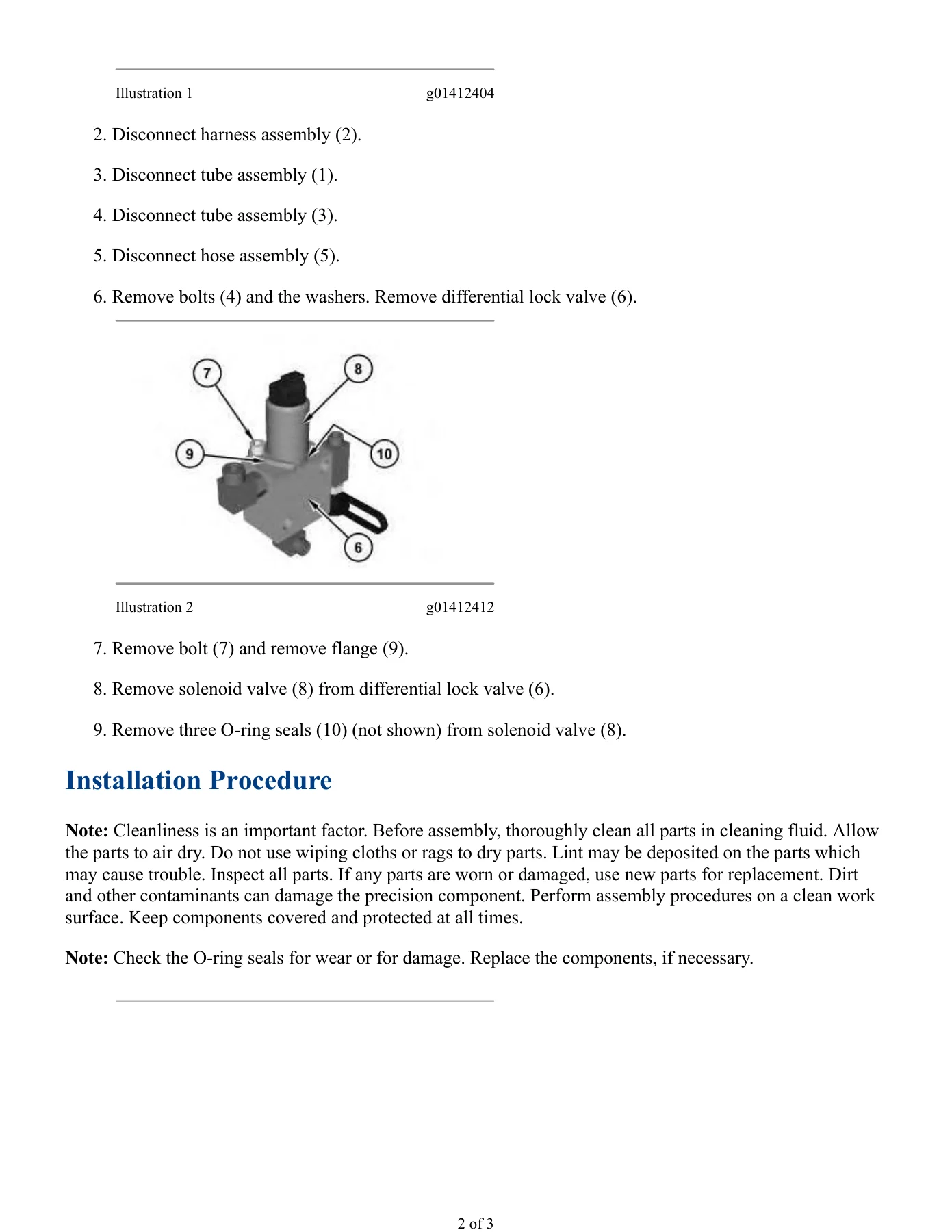
- Differential Lock Valve – Remove and Install
- Drive Chain – Install / Remove
- Drive Shaft – Remove and Install
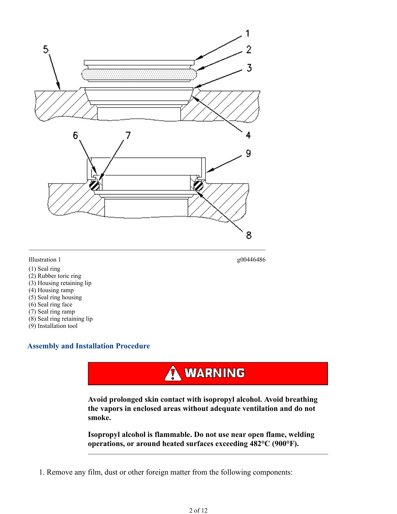
- Duo-Cone Conventional Seals – Install
- Gear Group (All Wheel Drive) – Assemble / Disassemble / Install / Remove
- Gear Pump (Transmission Charging and Scavenge) – Assemble / Disassemble / Install / Remove
- Housing (Tandem) – Remove and Install
- Modulating Valve (Transmission Clutch) – Assemble / Disassemble / Install / Remove
- Parking Brake – Install / Remove
- Piston Motor (Wheel Propel) – Assemble / Disassemble / Install / Remove
- Rear Axle, Differential and Final Drive – Assemble / Disassemble / Install / Remove
- Relief Valve (Main) – Assemble / Disassemble / Install / Remove
- Service Brake (Wheel Spindle) – Assemble / Disassemble / Install / Remove
- Steering Frame Lock – Separate and Connect
- System Pressure – Release
- Transmission – Assemble / Disassemble / Remove
- Transmission Oil Cooler – Install / Remove
- Transmission Oil Filter Base – Assemble / Disassemble / Install / Remove
- Wheel Spindle and Wheel Spindle Housing – Install / Remove
- Wheel and Tire (Rear) – Remove and Install
Transmission Overhaul and Clutch Pack Assembly
The transmission chapter is the deepest single section of this Caterpillar 12M Series 3 power train manual, walking the technician through complete tear-down and rebuild of the 12M3, 140M3 and 160M3 transmission. It covers gear train assembly, clutch pack stacking and orientation, piston seal ring installation, valve assembly installation, seal carrier torques and speed sensor placement, with every step tied to a numbered illustration and a required-tooling callout. Disassembly mirrors the assembly order in reverse, letting you strip the unit in the same sequence the factory built it.
Rear Axle, Differential and Final Drive
Full assemble, disassemble, install and remove coverage for the rear axle assembly on these motor graders. The section documents bevel gear and pinion setup in detail, including shim pack measurement, backlash measurement, and Prussian blue tooth-contact pattern checks so you can dial in the differential correctly rather than by feel. Ring gear, spider assembly, planetary carriers, axle shafts, bearing cones and wear sleeves are all covered, along with final drive housing installation and the torque values that go with each fastener.
All-Wheel Drive Gear Group
The AWD gear group section covers the wheel-end planetary reduction for the 12M3, 140M3 and 160M3 all-wheel-drive configuration. Assembly walks you through the planetary, roller assemblies, races, Duo-Cone seal installation, brake piston, first reduction and clutch plate/friction disc stack with specific torque values at each stage. Disassembly reverses the process and calls out the tooling needed to separate the spindle from the housing and to remove retaining rings under spring load.
Piston Motor (Wheel Propel)
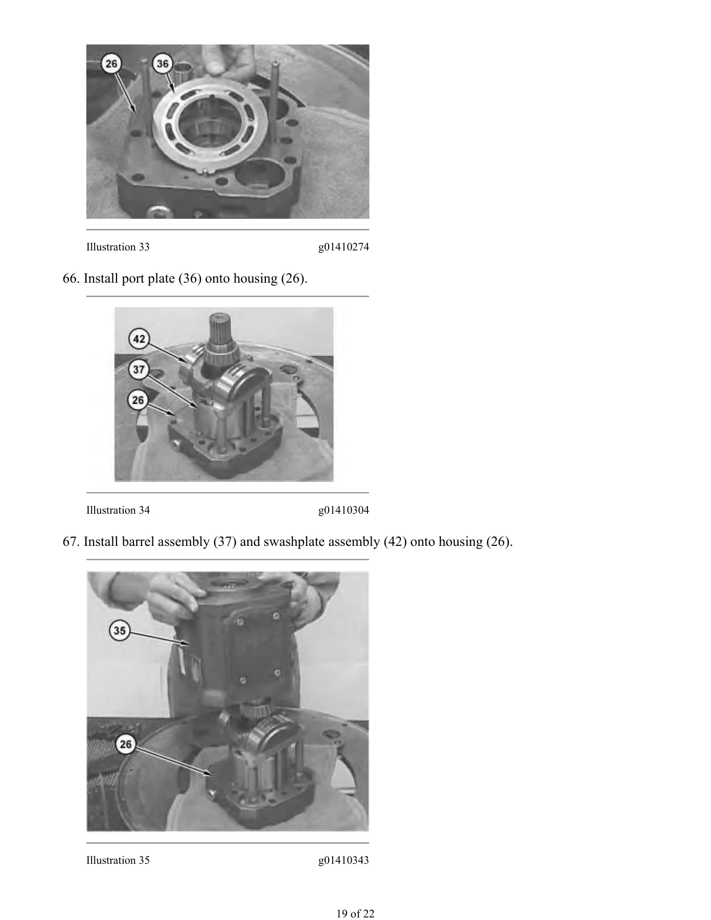
The wheel propel piston motor chapter is a full hydrostatic motor overhaul. Shimming routines for the cradle bearing preload, barrel and swashplate clearances, slipper clearance and port plate measurements are all laid out step-by-step with the dimensions you need to record and calculate. The section covers bearing cone and race installation temperatures, seal installation, valve assembly and cover torque sequencing, so the finished motor goes back on the machine with the correct internal clearances rather than just a fresh set of seals.
Service Brake and Parking Brake
Both brake systems are documented end to end. The service brake (wheel spindle) section covers Duo-Cone seal installation, bearing cup and cone fitting, piston and disc/plate stacking, cover torquing under spring compression, retainer shimming and the compensator adjustment procedure used to set the correct running clearance. The parking brake section covers spring plate removal under controlled release, coned disc spring orientation, piston and O-ring seal replacement, solenoid and pressure sensor installation, and the exact torque for the retaining bolts.
Drive Chains, Drive Shaft and Tandem Housing
The drive chain procedures on this 12M3/140M3/160M3 power train manual cover both removal and installation with the required Cat tooling, including chain pullers, lift stands, punch and air hammer for master link work. Clear notes on cotter pin direction, master link positioning relative to sprocket tooth spaces, and cover gasket torque values help avoid the classic chain interference and rework issues. The tandem housing remove-and-install procedure is documented with lifting weights, O-ring seal replacement and the bolting caution about not using the corner final-drive bolts to pull the housing into contact.
Gear Pump, Relief Valve and Modulating Valves
The transmission charging and scavenge gear pump is covered in assemble, disassemble, install and remove order, with sleeve bearing depth and joint angle measurements, gear, key and body orientation, and manifold O-ring sealing. The main relief valve section covers the full valve stack, including spring-loaded ball, retainer, spool slug and cover torques. The transmission clutch modulating valve section walks through solenoid, cartridge and spool/servicing on the bench plus installation torque and harness routing back on the machine.
Wheel Spindle and Front Axle End Assemblies
The wheel spindle and wheel spindle housing install/remove procedures cover bearing installation via hydraulic puller, seal and thrust washer fitting, pin installation depth, steering cylinder and tie rod nut torque, and cotter pinning. Rear wheel and tire remove and install is included with the correct bolt torque and lifting weights. If you are pulling a spindle to replace bearings or a leaking seal, this is the section you will use.
Duo-Cone Conventional Seal Installation
This manual includes the full Caterpillar Duo-Cone Conventional Seal installation procedure used across the wheel spindle, gear group, service brake and rear axle sections. It explains rubber toric ring preparation, correct use of the installation tool, assembly height measurement with a dial indicator, and the failure modes that follow from twisted or incorrectly seated toric rings. Anyone rebuilding a wheel end, final drive or brake on these machines needs this section open before touching a seal.
Preparation, Safety and System Pressure Release
The manual opens each procedure with the standard Caterpillar warnings about fluid containment, cleanliness and spring-loaded component hazards, and includes the steering frame lock procedure (separate and connect) and the system pressure release step that must be completed before any hydraulic component is opened. Following these in sequence avoids both injury and contamination of the precision components in the transmission, gear group and piston motor.
Tooling and Torque References
Every procedure in this UENR3483 PDF opens with a required-tools table listing the Caterpillar part numbers you need, from link brackets, lever puller hoists and transmission repair stands to bearing puller groups, driver groups, hydraulic pumps and thread lockers. Torque values are printed inline at the point of use – retaining bolts, cartridge assemblies, cover bolts, sensor ports and final drive nuts – so you are not scrolling back to a spec section to find them. If you are running a shop or working on your own 12M3, 140M3 or 160M3 motor grader, this is the practical reference that keeps the tool list and the torque values in the same place as the procedure.
What This Caterpillar 12M3 140M3 160M3 Power Train Manual Delivers
If you are tearing down a transmission, chasing a wheel propel fault, rebuilding an all-wheel-drive gear group, replacing a service brake, or pulling a final drive on a 12M Series 3, 140M Series 3 or 160M Series 3 motor grader, this is the factory procedure set that matches the machine. It carries the exact disassembly order, the correct fastener torques, the measurement routines for shim packs and bearing preloads, and the tooling list for each job – so you can complete the repair to the same standard the machine was built to, not the standard of a generic guide that skips half the steps.
IMAGES PREVIEW
Instant PDF Delivery
This Caterpillar motor grader power train disassembly and assembly manual is delivered as a PDF immediately after payment – no shipping, no waiting, no lost paper copy in the shop. Open it on a laptop, tablet or phone at the machine, print the sections you need for the job at hand, and keep the rest of the 377 pages tucked away until the next repair. Buy it once and it stays with you for every future service on your 12M3, 140M3 or 160M3.
Reviews
There are no reviews yet.