
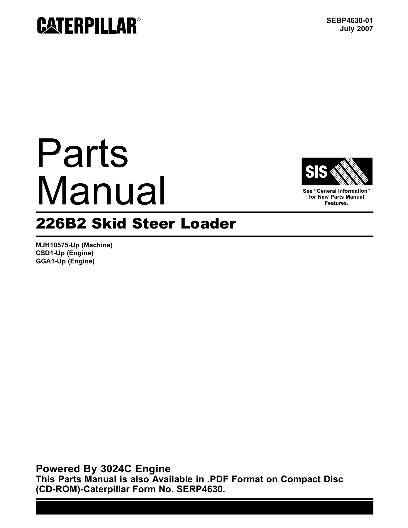
Caterpillar 226B2 Skid Steer Loader Parts Manual 2007 – SEBP4630-01 PDF Download
Original price was: $52.95.$34.95Current price is: $34.95.
Complete Caterpillar 226B2 Skid Steer Loader parts manual SEBP4630-01 (2007) — 706-page PDF with exploded views, parts lists and part numbers for every major assembly. Instant download.
Description
Caterpillar 226B2 Skid Steer Loader Parts Manual — SEBP4630-01 (2007)
When you need the exact part that fits a 226B2 Skid Steer Loader, a generic aftermarket catalogue is not good enough — you need the Caterpillar parts manual that was printed for the machine. This is SEBP4630-01, the Caterpillar 226B2 Skid Steer Loader parts manual dated 2007, presented as a complete PDF that covers every major assembly on the machine. From the engine block to the operator station, every illustration and parts list is keyed to the machine’s serial-number range (machine MJH10575-UP; engine GGA1-UP and CSD1-UP), so you can trace any part back to the exact configuration as built.
File Details
- Manual type: Parts manual (parts catalogue with exploded illustrations and serviceable consist lists)
- Brand / manufacturer: Caterpillar
- Model: 226B2 Skid Steer Loader
- Publication number: SEBP4630-01
- Edition / date: 2007
- Language: English, with multilingual front matter (French, Spanish, Portuguese and German sections covering product/dealer information and contents listings)
- File format: PDF
- Page count: 706 pages
- Serial-number coverage: Machine MJH10575-UP; engine GGA1-UP and CSD1-UP
Chapters Covered
The manual opens with general information, repair alternatives, supplemental coolant additives, a maintenance-parts index and the master index, then moves into the machine’s build sections:
- General Information
- Repair Alternatives
- Supplemental Coolant Additives
- Maintenance Parts
- Machine Arrangement
- Engine Arrangement
- Basic Engine
- Cooling System
- Air Inlet and Exhaust System
- Fuel System
- Electrical and Starting System
- Power Train
- Frame and Body
- Hydraulic System
- Work Tools
- Operator Station
- Service Equipment and Supplies
General Information, Repair Alternatives and Maintenance Parts
The opening chapters explain how a Caterpillar machine is identified by Product Identification Number (PIN) and serial number, how to order replacement parts, and how the parts manual itself is organised. A maintenance-parts index lists the most frequently ordered service items — filters, belts, seals, batteries, fuses and similar consumables — with quantity and the pages they appear on. The multilingual front matter also repeats the product and dealer information sheets in several languages, with the contents listings printed as TABLE DES MATIERES (French), CONTENIDO (Spanish), ÍNDICE (Portuguese) and INHALTSVERZEICHNIS (German) so the same document can be used across markets.
Machine Arrangement and Engine Arrangement
These sections give the top-level arrangement of the machine and its engine. The machine arrangement chapter lists the major sub-assemblies the loader is built from — chassis, common arrangement, machine-control arrangement and the various conversion arrangements used for roading and non-roading markets. The engine arrangement chapter breaks the engine down into its primary arrangement, the installation arrangement in the machine, and the sub-assemblies that make up the engine assembly itself.
Basic Engine
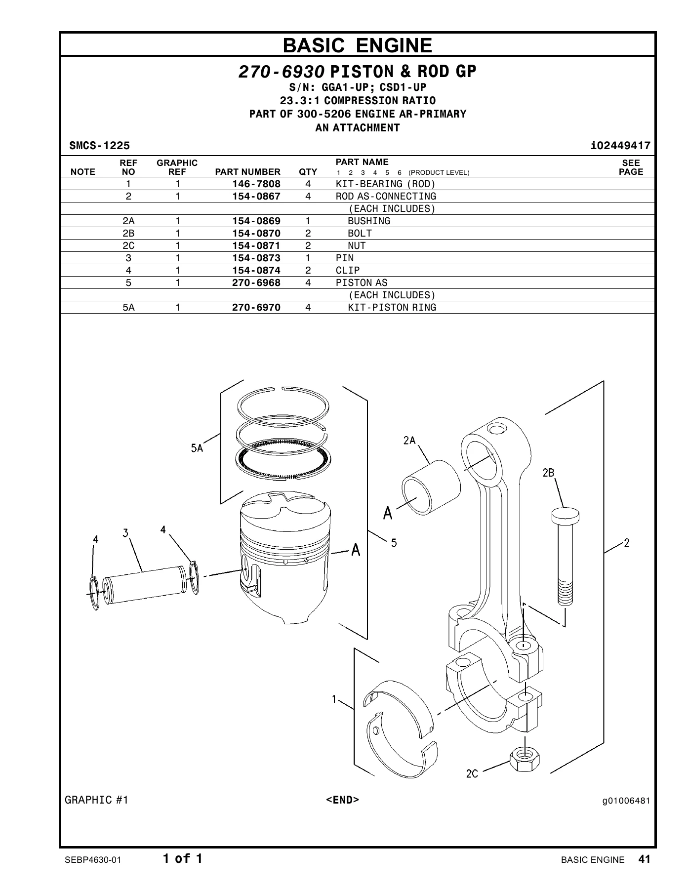
This is the core of the engine side of the book. It covers the camshaft group, valve-mechanism cover, crankshaft group, cylinder block, cylinder head, engine-oil drain, flywheel, belt guard, flywheel housing, front housing, engine lifting, engine and fan mounting, oil pan, piston and rod group, crankshaft pulley, water-pump pulley, and the complete valve mechanism. Each group has its own exploded illustration with a numbered parts list that shows part number, quantity and description for every serviceable item in that assembly.
Cooling System
The cooling-system chapter covers the radiator and hydraulic-oil cooler group and its mounting, the water pump, the water-temperature regulator, the coolant-recovery bottle and the hoses and clamps that link them. Parts are listed for both the standard radiator-and-oil-cooler arrangement and the Stage II sound-suppressed arrangement used on certain conversion packages.
Air Inlet and Exhaust System
The air-cleaner group, air lines, exhaust manifold, muffler group and turbocharger group are all covered here, with the associated gaskets, clamps, elbows and mounting hardware. This is the chapter you go to when you are chasing air-intake leaks, replacing a turbocharger, or fitting a replacement muffler on a sound-suppressed machine.
Fuel System
Fuel-system coverage includes the governor control cable and pedal, the governor group, the water-separator and fuel filter, the primary fuel filter and priming lines, the fuel transfer pump and its mounting, the fuel-injection pump, and the fuel priming pump. Each assembly is illustrated with a complete consist list, so you can order the exact injector, seal or line without guessing.
Electrical and Starting System
This is one of the larger chapters. It covers the alternator and charging system, batteries (standard and heavy-duty maintenance-free), electrical connections, the interlock control, non-roading conversion, fuse-panel cover, implement electronics, wiring-harness fasteners, glow plugs, jacket-water heaters (120 V and 240 V), security installation, work-tool control and wiring kits, flood and head lamps, stop and tail lamps, warning beacon, roading, flood, stop-and-tail and warning-beacon lighting groups, temperature and pressure sensors, the machine service group, electric starting motor, pressure switch, backup warning, and the air-conditioner, chassis, engine, horn, machine, rear-lighting and work-tool wiring groups. The wiring groups are shown as harness layouts with connector call-outs rather than full circuit schematics, but they are detailed enough to trace a lamp, switch or relay back to its connector.
Power Train
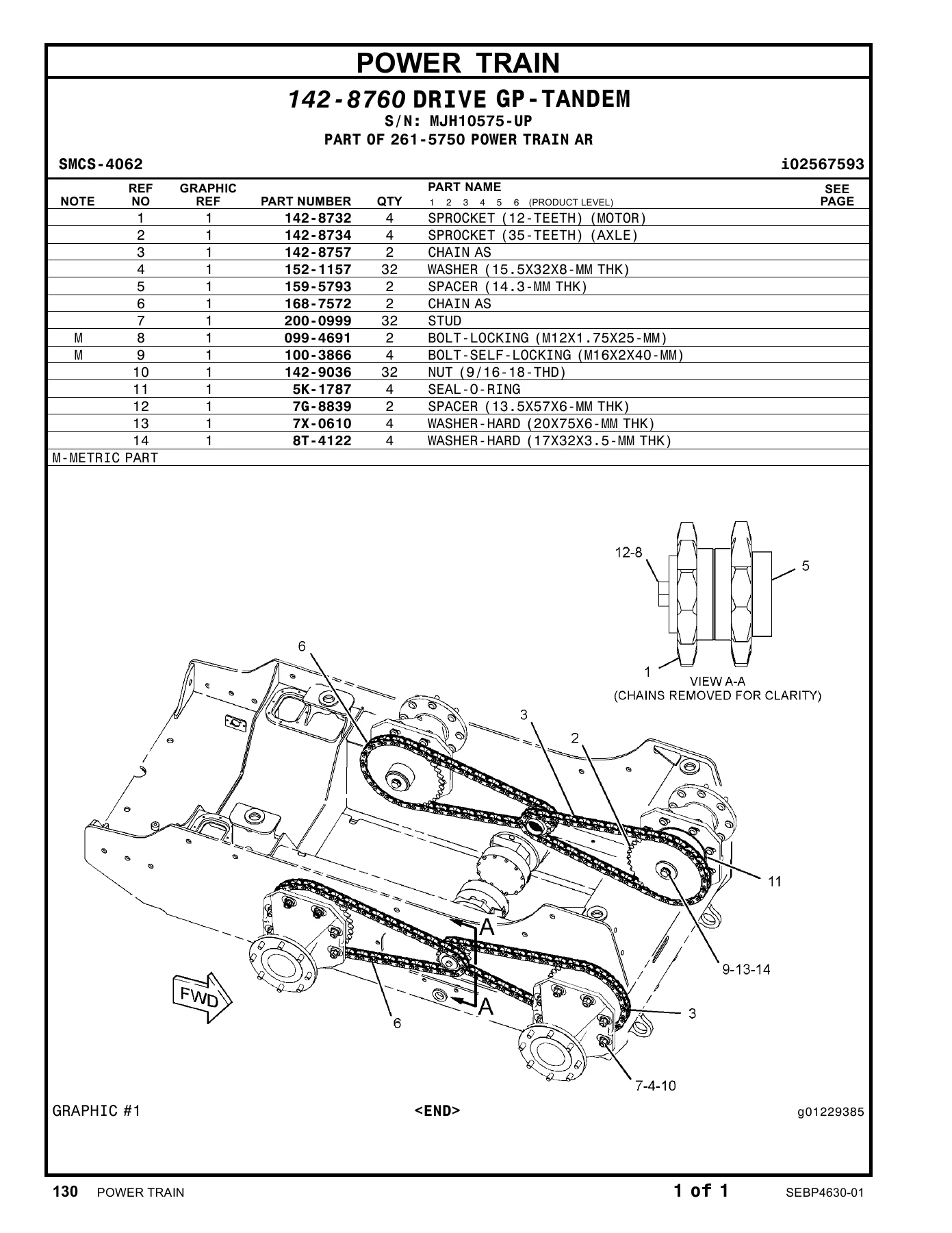
The power-train chapters group the axle assemblies, the tandem drive, the hydraulic filter and lines, the hydraulic-oil filter, hydrostatic lines, return manifold, hydrostatic motor and its mounting, piston motor, pump mounting, the complete power-train arrangement, hydrostatic pump and mounting, piston pump, and the tire-and-rim and wheel-and-tire groups. The hydrostatic components are listed with their internal cartridges, seals and bearings, which makes this chapter useful when a drive motor or pump needs to come apart.
Frame and Body
Frame-and-body coverage includes the rear bumper, the roading-conversion arrangements (Europe, Germany, Italy, United Kingdom and the associated high-flow variants), counterweights (standard and kit), engine enclosure, loader frame, machine frame, line guide, roading-conversion kit, machine lifting groups (single-point and 4-point), rear-view mirror and mounting, registration mounting and roading-light mounting, and the sound-suppression group. Conversion arrangements are listed by region, so you can tell at a glance which parts belong to which market package.
Hydraulic System
This is the largest single section of the manual and the one most owners and independent shops reach for. It covers hydraulic accumulators and mounting, oil-line adapters, angle-blade cylinders, bucket cylinders and their mounting, lift-arm cylinder groups, bucket cylinders, grapple cylinders, hydraulic cylinders generally, lift cylinders (LH and RH), tilt cylinders (bucket ejector, LH and RH), hydraulic fittings (including the high-flow quick-disconnect fittings), the complete hydraulic arrangements, high-flow conversion kit, quick-coupler conversion kit, bucket lines (including the industrial variant), connecting lines, grapple lines, hydraulic-fan lines, hydraulic-oil-cooler lines, lift-cylinder lines, lowering-control lines, pilot lines (direction/speed and work-tool), pump lines, tilt-cylinder lines, work-tool lines, control manifolds and lines, control manifold and mounting, control manifold and solenoid, control manifold, hydraulic-fan motor and mounting, gear motor, cylinder mounting, pilot-valve plug, work-tool pump and mounting, gear pump, hydraulic tank and mounting, hydraulic tank, coupler valve and lines, control valve and mounting, control valve, manual-resolver valve, pilot valve, relief valve, and solenoid valves. Every cylinder, valve, hose assembly and manifold is illustrated with an exploded view and a full consist list.
Work Tools
The work-tools section covers the entire attachment range offered for the 226B2: material-handling arm, angling blades (1829 mm, 2134 mm and the 2007 mm version), multipurpose buckets, dirt buckets, general-purpose buckets, grapple buckets, light-material buckets, multipurpose buckets (60, 66, 72 and 78 in), utility buckets (60, 66 and 72 in), carriage and fork arrangements, fork and grapple arrangements, grapples, pallet forks, utility forks, blade frames, grapple frames, fork frames, coupler handles and pins, coupler links, coupler locks, roading plates, blade springs, material-handling steps, grapple stops, water strainer, water tank and mounting, water tank, and the universal tooth. If you run the loader with more than one attachment, the parts for each attachment live in this section.
Operator Station
The operator-station chapters cover everything the operator sees and touches: air-conditioner refrigerant accumulator, air-conditioner and mounting group, the air-conditioner arrangement, air-conditioner group, armrests and mounting, storage box, enclosed-ROPS cab, cab group, control cable, compressor and motor, refrigerant compressor and mounting, refrigerant condenser and mounting, handle controls, pilot-operated hydraulic controls, drive coupling, console covers, instrument-panel covers, cab doors and door mounting, cab-door glass, duct and control group, window frame, gauges and warning group, ROPS/FOPS guard, handhold, modular handle, cab heater and mounting, heater group, side housing, installation groups, cab air-conditioner and heater installation kit, cab-door and mounting kit, cab-seal kit, governor lever, cab liner, air-conditioner lines, heater lines, literature group, rear-view mirror, warning-indicator module, ROPS mounting, window group, cab seal, seat belt, seat, adjustable seat, gas spring, cab visor and cab windows. Options such as the cab arrangement, instrument panel, side panel, governor pedal, operator platform and seat are all covered.
Service Equipment and Supplies
The closing chapters cover the smaller support items: mounting brackets, film and identification plates, service-equipment and supplies listings, and the index of part numbers that lets you look up any part number in the manual and jump straight to the page that shows it.
What You Can Do With This Manual
Because every assembly is shown as an exploded illustration with a numbered parts list, this Caterpillar 226B2 parts manual lets you:
- Identify the correct part number for any component on the machine, down to bolts, seals, gaskets and hoses
- Confirm which configuration your machine was built with, using the serial-number coverage and the arrangement-by-arrangement layout
- Cross-check a part before ordering, so you do not end up with the wrong cylinder, valve or manifold on the bench
- Rebuild a cylinder, valve bank, hydrostatic motor or pump using the exploded views as your disassembly and reassembly reference
- Look up a part from the numeric index if you already know the number and just need the page
- Compare market-specific conversion arrangements (Europe, Germany, Italy, United Kingdom, high flow) so you know exactly what your machine was originally fitted with
Why the Right Parts Reference Matters
On a skid steer loader, the wrong part is not a cosmetic problem — a mismatched hydraulic fitting, relief valve or cylinder can leak, stall the machine mid-job, or damage a component further up the circuit. The Caterpillar 226B2 parts manual takes the guesswork out of ordering by tying every part number back to a specific assembly and a specific serial-number range. Whether you are an owner doing your own maintenance, an independent shop working on a customer’s machine, or a parts counter checking a fitment, having the original Caterpillar parts listing in front of you is the difference between one correct order and three wrong ones.
IMAGES PREVIEW
Instant PDF Delivery
The manual is delivered as a PDF, so there is no shipping, no waiting for a parcel, and no risk of a damaged paper copy. Once your order is placed, the download is available immediately. The file opens on any device — desktop, laptop, tablet or phone — and you can print the pages you need for the workshop, or keep the whole 706-page book on a tablet at the machine. If you work on more than one 226B2, the same PDF covers every serial number from MJH10575-UP onward, and the engine range from GGA1-UP and CSD1-UP. Keep a copy in the office, keep a copy on the shop computer, and you always have the Caterpillar parts information at hand when the next job comes in.
Reviews
There are no reviews yet.