
Cessna Electronics Parts Catalog & Maintenance Manual D-144 1962 – Models 150 172 175 180 182 185 210
Original price was: $39.95.$23.95Current price is: $23.95.
Complete 1962 Cessna electronics service manual D-144 covering radio systems, illustrated parts breakdowns, wiring diagrams, and maintenance procedures for Models 150, 172, 175, 180, 182, 185, and 210 single-engine aircraft.
Description
Cessna Electronics Parts Catalog & Maintenance Manual D-144 — 1962 Edition
This Cessna Electronics Parts Catalog and Maintenance Manual D-144 is the complete 1962 service reference for radio and electronic equipment installed in Cessna single-engine aircraft. Published 1 May 1962 and revised 20 October 1962, it combines an illustrated parts catalog, wiring and schematic diagrams, and a full electronics maintenance manual into one document. Whether you are restoring a vintage Cessna, troubleshooting a Narco Omnigator, or sourcing a Lear LNC-100A mounting bracket, this manual provides the parts numbers, wiring details, and service procedures needed to keep the avionics systems operational.
File Details
- Manual type: Electronics Parts Catalog & Maintenance Manual
- Brand: Cessna
- Document number: D-144
- Date: 1 May 1962, Revised 20 October 1962
- Models covered: 150, 172, 175, 180, 182, 185, 210
- Language: English
- Page count: 505
- File format: PDF
Chapters Covered
The manual is organized into five sections, each with its own table of contents:
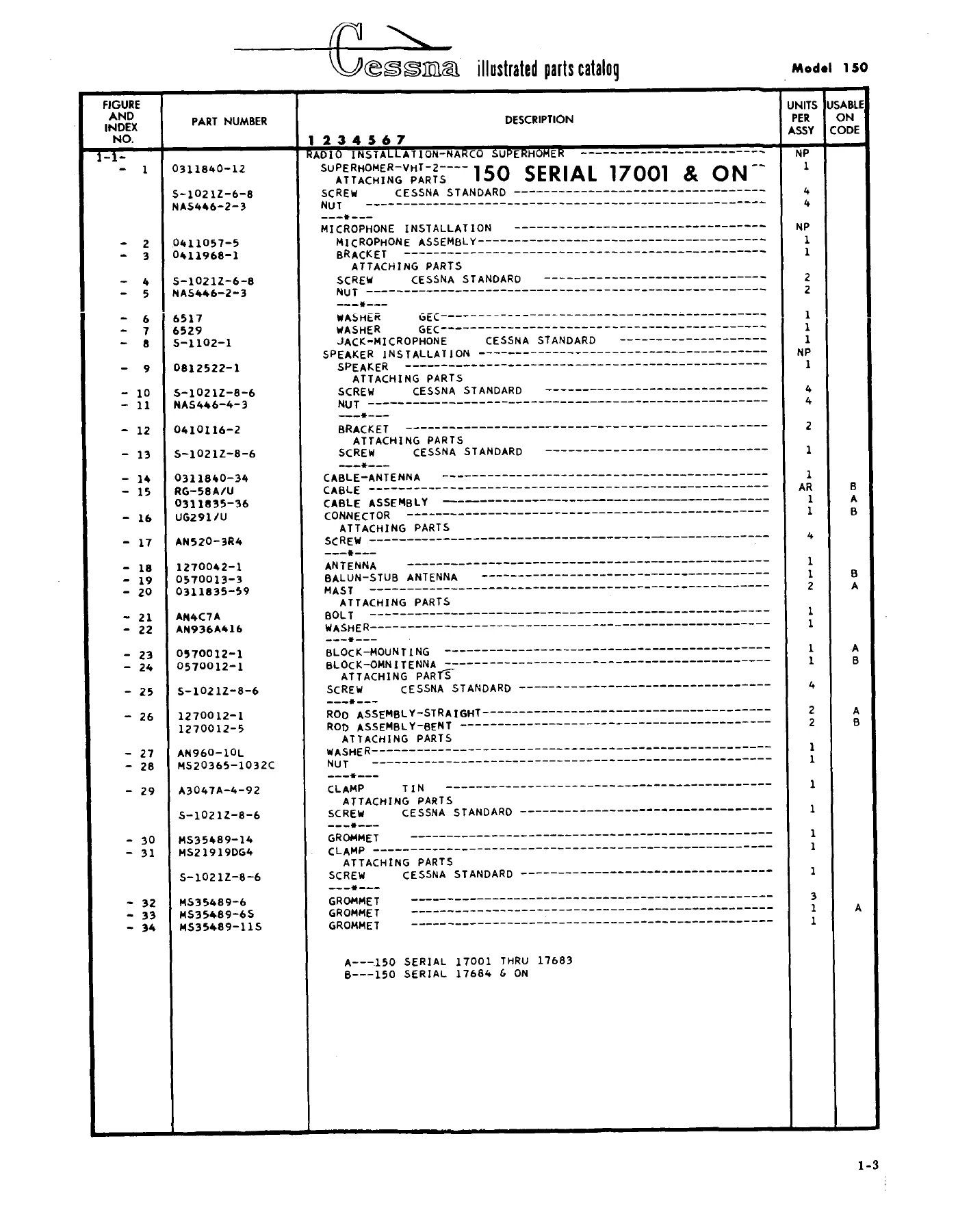
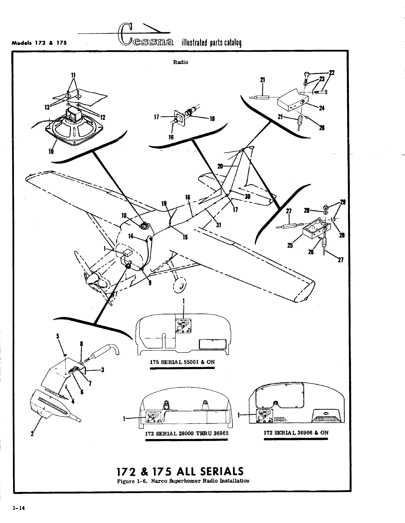
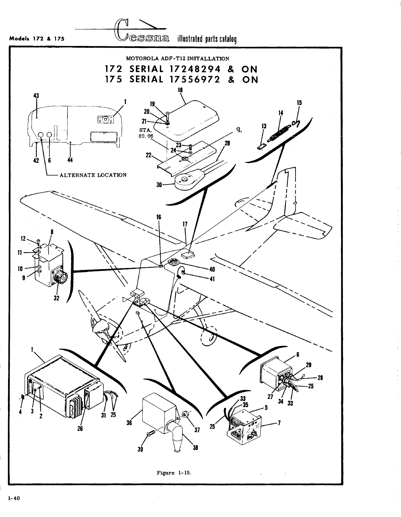
- Section I — Illustrated Parts Catalog: Complete parts breakdowns with figure and index numbers, part numbers, descriptions, units per assembly, and usable-on codes for every radio installation.
- Section II — Wiring and Schematic Diagrams: Detailed wiring diagrams and isometric location drawings for each model and radio system.
- Section III — Electronics Maintenance Manual: Bench test and adjustment procedures for ADF, VHF transceivers, receivers, isolation amplifiers, and navigation equipment.
- Section IV — ARC F-503A Audio Isolation Amplifier Manual: Purpose, specifications, installation, operation, maintenance, performance tests, wiring diagram, schematic, and parts list.
- Section V — Cessna Nav-O-Matic Manual: Automatic flight controller system maintenance, installation, operation, adjustment procedures, troubleshooting, voltage measurements, removal and replacement, operational checks, schematic and wiring diagrams, and parts lists.
Radio systems covered in the illustrated parts catalog include:
- Narco Omnigator
- Sunair Radio, Sunair T-5D, Sunair T-5DA
- King KY-90, King KX-100
- Narco Simplexer
- Narco LFR-3
- Narco Mark V
- Lear LNC-100A, Lear LNC-100B
- Motorola M-135
- ARC Radio
- Narco MBT-12
- Lear ADF-12, Lear ADF-12E-2
- Motorola ADF-T12
- ARC ADF-501A
- Narco UGR-1
- Narco UDI-2 DME
- Radio Cooling System
- VHF Antenna Installation
- Omni-Antenna Installation
- Microphone Installation
- Speakers Installation
- Marker Beacon Antenna Installation
Section III of this Cessna electronics manual walks through bench test and adjustment procedures for a wide range of avionics. Automatic direction finders covered include the ARC 501A, ARC Type 21, ASL Birdog RDF-2, Motorola ADF-12, and Motorola ADF-T12, with detailed instructions for IF peaking, RF tracking, loop compensation, phase detector alignment, and pre-flight quadrantal error compensation. Audio isolation amplifiers covered include the ARC F-13A, ARC F-503A, King KA-10, and King KA-11. Glide path receiver coverage includes the Narco UGR-1. High frequency transceivers covered include the Sunair S5-DTR, S5-RTR, T5-DA, and T-10, with alignment procedures, crystal installation, tuning coil and capacitor selection, and antenna loading coil adjustment. Low frequency receiver coverage includes the Narco LFR-3. Marker beacon receiver coverage includes the Narco MBT-12. VHF transceivers covered include the Narco Mark II Omnigator, Narco VHT-3 Superhomer, Narco VC-27 Simplexer, Narco Mark V with VOA-3 converter, Motorola M-135, and King KX-100. VHF transmitters covered include the ARC T-11B and T-22. Omnireceiver coverage includes the ARC Type 15 Navigation System.
Section V provides complete maintenance instructions for the Cessna Nav-O-Matic automatic flight controller system. This includes the Controller Amplifier, Rate Gyro, and Actuator. The section covers principles of operation, engagement of autopilot, attitude hold, heading hold, test equipment, mechanical inspection, lubrication, performance checks, adjustment procedures, troubleshooting, voltage measurements, removal and replacement procedures, operational checks using a portable test meter, operational checks without a test meter, and complete schematic and wiring diagrams plus parts lists for the actuator assembly, controller amplifier assembly, rate gyro, and Nav-O-Matic installation.
The illustrated parts catalog uses a clear system: figure and index numbers keyed to illustrations, part numbers for procurement, descriptions with indentation showing assembly relationships, and units per assembly. Usable-on codes indicate which serial numbers each part applies to. The catalog also explains interchangeable and non-interchangeable parts, accessory kits, bulk items, and how to order. Standard hardware items use AN and NAS numbers, while parts with standard usage carry the “S-” prefix. The manual notes that some electronics equipment installed in Cessna aircraft but discontinued by 1959 is not included.
Serial number ranges covered include 150 serial 17001 & ON, 150 serial 17001 THRU 15059350, 172 serial 28000 THRU 36965, 172 serial 36966 & ON, 172 serial 17247747 & ON, 175 serial 55001 & ON, 175 serial 17557003 & ON, 180 serial 30000 & ON, 180 serial 18051064 & ON, 182 serial 33000 & ON, 182 serial 18253599 & ON, 185 serial 185-0001 & ON, and 210 serial 57001 & ON, among others. The specific serial applicability is noted throughout the parts lists for each figure.
This Cessna D-144 manual covers a wide range of antenna installations including VHF antenna installations A and B, omni-antenna installations A, B, C, and D, microphone installations A, B, C, and D, speaker installations A, B, C, and D, and marker beacon antenna installation. The omni-antenna section covers both straight and bent rod antennas, balun stubs, mounting blocks, and cable assemblies for different aircraft models and serial ranges. The microphone section covers bracket mounting, jack installation, insulating washers, and microphone assemblies for different configurations.
For the radio cooling system, the manual covers the scoop, adapter, hose, clamps, plenum assembly, and spring. This system is applicable to the Model 210. The manual notes that an accessory kit is available, referenced as Kit QAK182-87.
What This Manual Enables You to Do
This Cessna electronics parts catalog and maintenance manual gives you the information needed to service, repair, and maintain the radio and electronic systems in Cessna 150, 172, 175, 180, 182, 185, and 210 aircraft. You can identify and order correct parts using the illustrated parts breakdowns and part numbers. You can trace wiring using the wiring and schematic diagrams. You can perform bench tests and adjustments on ADF systems, VHF transceivers, receivers, isolation amplifiers, and navigation equipment. You can troubleshoot the Nav-O-Matic autopilot system using the performance checks, troubleshooting charts, and voltage measurements. You can perform operational checks with or without a portable test meter. You can remove and replace components using the detailed procedures. You can rig and adjust the Nav-O-Matic system after installation.
Having the correct procedures and specifications matters because avionics systems require precise adjustment to function properly. Incorrect alignment of an ADF loop, improper tuning of a transceiver, or wrong adjustment of the Nav-O-Matic sensitivity can lead to poor performance or system failure. This manual provides the test equipment requirements, adjustment values, and step-by-step procedures to get it right. The parts catalog ensures you order the correct part for your specific aircraft serial number, avoiding the frustration of incompatible components.
IMAGES PREVIEW
This Cessna D-144 manual is delivered as an instant PDF download after payment. No shipping, no waiting for a physical book. You can view it on any device, print the pages you need for the hangar or bench, and keep the complete manual on hand for reference. Whether you are a licensed aircraft mechanic, an avionics technician, or a Cessna owner maintaining a vintage aircraft, this manual provides the factory information needed to service these classic radio systems.
Reviews
There are no reviews yet.