★ TRUSTED BY 321,897+ PROFESSIONALS WORLDWIDE
🏒
Trusted Business
Verified & Licensed
πŸ›‘οΈ
Virus Free Files
100% Safe Downloads
πŸ”’
Secure Payment
SSL Protected
⚑
Instant Delivery
Available Immediately
Sale!

Cessna FR172 Series 1968-1976 Reims Rocket Illustrated Parts Catalog P534-12

Original price was: $44.95.Current price is: $26.95.

Cessna FR172 Series (Reims Rocket) 1968-1976 Illustrated Parts Catalog, publication P534-12, including Temporary Revisions 1 through 3. Instant 466-page PDF with illustrated figures, part numbers, quantities and serial-coded usage.

⚑
Instant PDF Download
Available immediately
πŸ’Ύ
Save to Your Device
Download & keep forever
πŸ›‘οΈ
Antivirus Scanned
100% virus-free
🌍
Trusted Worldwide
175,000+ customers

Description

Cessna FR172 Series 1968-1976 Illustrated Parts Catalog P534-12

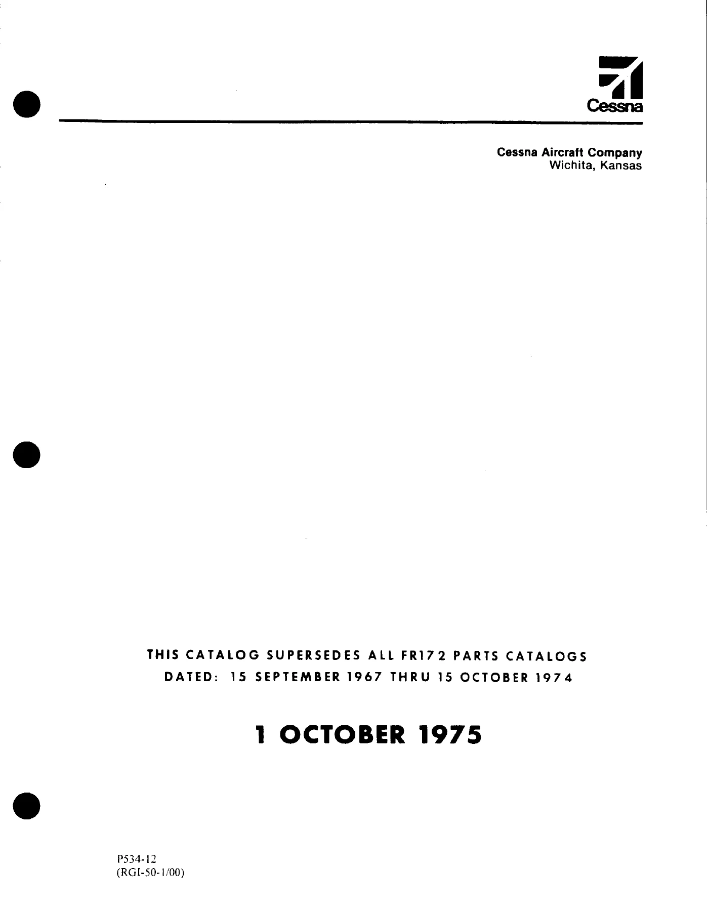
The Cessna FR172 Series 1968-1976 Illustrated Parts Catalog (P534-12) is the complete parts breakdown for the FR172 series, marketed under the popular name Reims Rocket. Published by Cessna Aircraft Company of Wichita, Kansas and dated 1 October 1975, it supersedes every earlier FR172 parts catalog dated 15 September 1967 through 15 October 1974. This PDF also carries all three temporary revisions, the latest dated 1 October 2010, so the Cessna FR172 parts catalog you download includes the later corrections as well as the 1975 original.

File Details

  • Manual type: Illustrated Parts Catalog
  • Manufacturer: Cessna Aircraft Company, Wichita, Kansas
  • Model: FR172 Series, 1968 through 1976 (Reims Rocket)
  • Publication number: P534-12 (paper copy) and P534-12AF (aerofiche)
  • Original issue: 1 October 1975
  • Revisions included: Temporary Revision 1 (5/01/92), Temporary Revision 2 (17 February 1995), Temporary Revision 3 (1 October 2010)
  • Language: English
  • Pages: 466
  • File format: PDF

Serial Numbers and Model Years Covered

Parts in this FR172 illustrated parts catalog are tied to airplane serial numbers through usable-on codes, and the interior trim tables break the production run out by model year:

  • 1968: FR172-0001 THRU FR172-0060
  • 1969: FR172-0061 THRU FR172-0145
  • 1970: FR17200146 THRU FR17200225
  • 1971: FR17200226 THRU FR17200275
  • 1972: FR17200276 THRU FR17200350
  • 1973: FR17200351 THRU FR17200440
  • 1974: FR17200441 THRU FR17200530
  • 1975: FR17200531 THRU FR17200559 and FR17200561
  • 1976: FR17200560 and FR17200562 and on

How the FR172 Parts Lists Are Organized

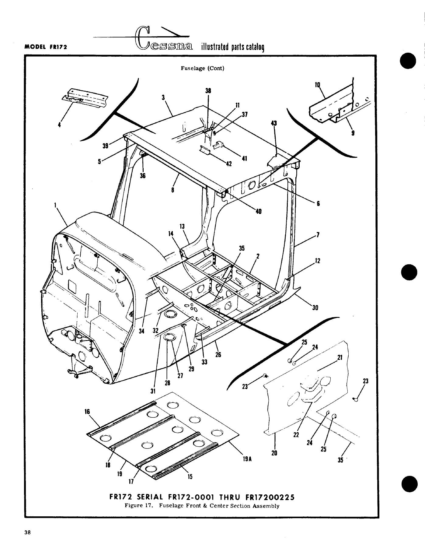
Each figure pairs an illustration with a parts list. The index numbers on the illustration are keyed to the list, which gives the part number, a description whose indention shows how assemblies nest, the units per assembly, and a usable-on code letter that ties each part to a specific block of serial numbers. Attaching parts are listed directly beneath the item they secure, and the quantity shown is what it takes to attach a single part. Where a later design part is fully interchangeable with an earlier one, the earlier listing carries a when-exhausted-use note so you know which number to order. The introduction explains the symbols NP (not procurable) and AR (as required, used for bulk quantities), the S prefix for Cessna standard parts, and the AN and NAS numbers used for standard hardware. The Cessna FR172 parts catalog is indexed at both ends: an alphabetical index at the front and a numerical index at the back that shows every figure in which a part number appears.

IMAGES PREVIEW

Cessna FR172 Series 1968-1976 Reims Rocket Illustrated Parts Catalog P534-12 β€” PDF page 1 preview
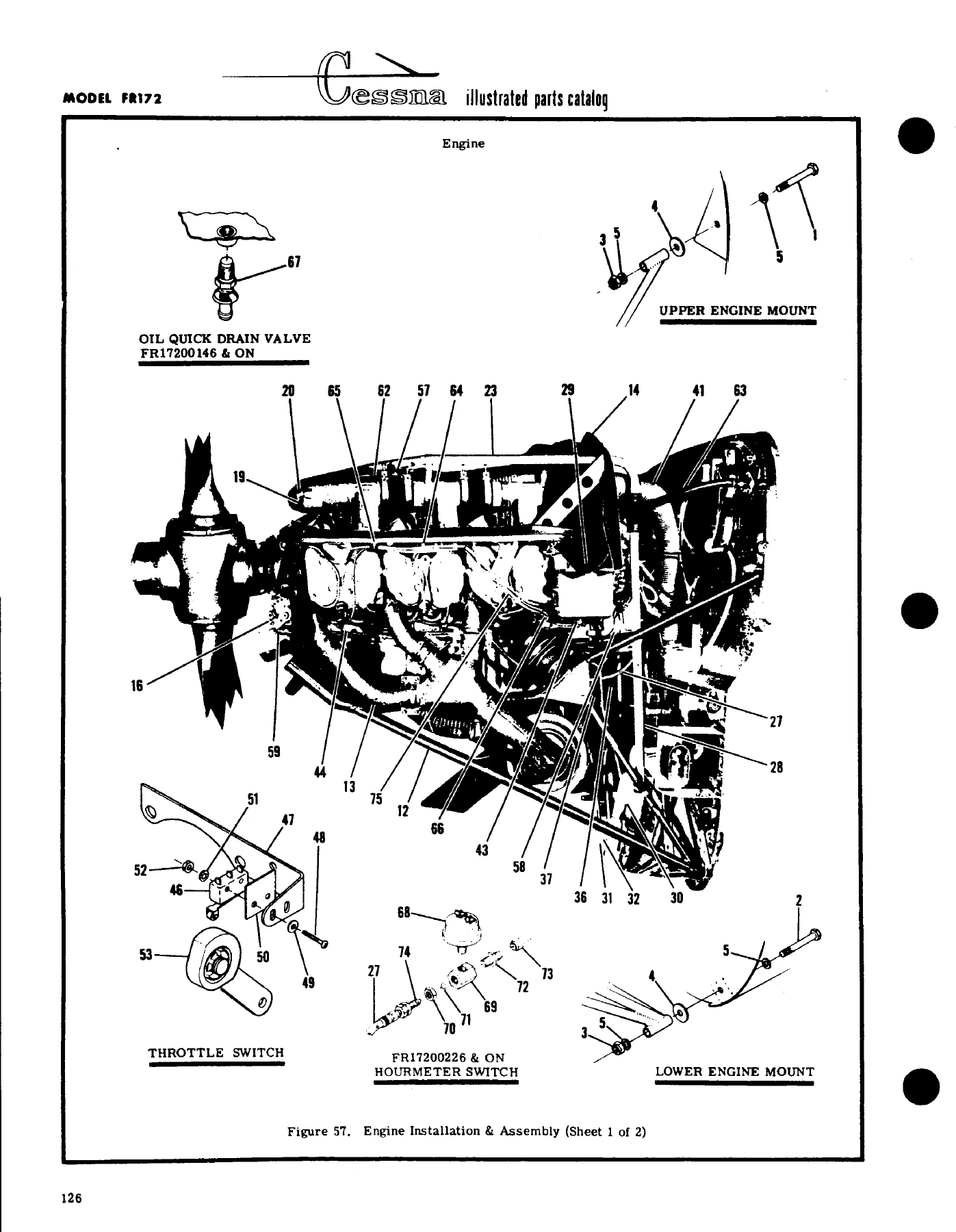
Cessna FR172 Series 1968-1976 Reims Rocket Illustrated Parts Catalog P534-12 β€” PDF page 106 preview
Cessna FR172 Series 1968-1976 Reims Rocket Illustrated Parts Catalog P534-12 β€” PDF page 310 preview

Chapters Covered

  • Introduction, symbols and part number terms, how to order parts
  • Finish and trim plate explanation and Model FR172 paint code charts
  • Upholstered parts and interior painted or plastic parts ordering tables, 1968 through 1976 model years
  • Alphabetical index
  • Figure 1 – Miscellaneous bulk items
  • Figure 2 – Placards, nameplates and exterior markings
  • Wing (Figures 3-11): complete wing, fuel tank well covers, structure assembly, leading edge, spars, skins and stringers, fuel tank installation, aileron, flap, wing strut
  • Empennage (Figures 12-15): fin, rudder, stabilizer, elevator trim tab actuator, elevator
  • Fuselage (Figures 16-29): fuselage assembly, front and center section, front section structure, front doorpost bulkhead, tunnel components, console structure, firewall and grommets, landing gear bulkhead, windshield, aft section, tailcone, battery box
  • Alighting gear (Figures 30-39A): nose gear and shock strut, heavy duty nose gear, nose wheels, shimmy dampeners, main landing gear, wheel and brake assemblies
  • Door and window (Figures 40-43A): left and right cabin doors, openable window doors, door latches, baggage door
  • Upholstery (Figures 44-49A): cabin top and firewall, side panels and floorboard, soundproofing, pilot and copilot seats, front seats, rear seat, auxiliary seat
  • Instruments (Figures 50-50F): instrument panel equipment installations and post lighted panel covers
  • Map compartment (Figure 51)
  • Fuselage equipment (Figures 52-53B): fuselage equipment, seat belt and shoulder harness, portable stretcher, refueling step and handle, static dischargers
  • Propeller and spinner (Figures 54-55A)
  • Cowl (Figures 56-56D): engine cowl assemblies and cowl flap control
  • Engine (Figures 57-61C): installation and assembly, components and accessories, induction air box and filter, propeller governor, exhaust system, baffles, oil filter
  • Winterization equipment (Figures 62-62A)
  • Cabin ventilation system (Figure 63)
  • Cabin heating and defrosting system (Figure 64)
  • Brake system, brake and rudder pedals, master brake cylinder (Figures 65-67)
  • Flight controls (Figures 68-73A): control yoke and wheel, aileron control, wing leveler, elevator control, elevator trim, electric flap system, rudder control
  • Pitot system and stall warning (Figures 74-75)
  • Fuel system, fuel strainer, fuel valve assemblies (Figures 76-78)
  • Engine driven vacuum system (Figures 79-79B)
  • Electrical equipment (Figures 80-88): electrical installation, instrument panel lights, landing lights, courtesy light, flashing beacon, map lights, alternator
  • Numerical index

Taken together, this FR172 Reims Rocket parts catalog lets you trace any assembly from the airframe to the engine compartment down to the individual nut, screw, bushing or placard. Variants that changed during the 1968-1976 production run, such as heavy duty nose gear, alternate wheel and brake assemblies, and different panel and seat installations, are listed in separate figures with their own usable-on serial codes. The correct part for a particular airplane is therefore the one whose code matches its serial number.

Paint, Upholstery and Interior Trim Ordering

Interior painted or plastic parts and upholstered parts need a second dash number for color and material. The catalog shows how to read the finish and trim plate on the left hand rear doorpost, then gives ordering tables by model year keyed to the interior color code. The paint code charts list exterior color combinations with their CES1054 dash numbers, and the ordering instructions note that adding the letters CP after a part number specifies corrosion proofing.

Complete PDF Bookmark Tree

Complete Bookmarks

The complete bookmarks in the β€œCessna FR172 Series 1968-1976 Reims Rocket Illustrated Parts Catalog P534-12” are as follows:

P534-12 – MODEL FR172 SERIES (1968 THRU 1976)p. 1
TEMPORARY REVISION NUMBER 3p. 2
TEMPORARY REVISION NUMBER 2p. 3
TEMPORARY REVISION NUMBER 1p. 8
LIST OF EFFECTIVE PAGESp. 9
INTRODUCTIONp. 10
STANDARD PARTSp. 10
SYMBOLS & PART NUMBER TERMSp. 10
GROUP ASSEMBLY PARTS LIST ARRANGEMENTp. 10
ACCESSORY KITSp. 11
BULK ITEMSp. 11
HOW TO ORDERp. 11
SERIAL, COLOR, & CORROSION PROOFINGp. 11
DISTRIBUTOR ORDERSp. 11
DEALER ORDERSp. 11
RETAIL ORDERSp. 11
FINISH & TRIM PLATEp. 12
PAINT CODE CHARTp. 13
PAINT CODE CHART 1968p. 13
PAINT CODE CHART 1969p. 13
PAINT CODE CHART 1978p. 14
PAINT CODE CHART 1971p. 14
PAINT CODE CHART 1972p. 15
PAINT CODE CHART 1973p. 15
PAINT CODE CHART 1974p. 16
PAINT CODE CHART 1975p. 17
PAINT CODE CHART 1976p. 18
UPHOLSTERY & INTERIOR TRIMp. 19
UPHOLSTERED PARTS – HOW TO ORDERp. 20
INTERIOR PAINTED OR PLASTIC PARTS HOW TO ORDERp. 21
INTERIOR PAINTED OR PLASTIC PARTSp. 22
INTERIOR PAINTED OR PLASTIC PARTS 1968 MODEL YEARp. 22
INTERIOR PAINTED OR PLASTIC PARTS 1969 MODEL YEARp. 23
INTERIOR PAINTED OR PLASTIC PARTS 1970 MODEL YEARp. 24
INTERIOR PAINTED OR PLASTIC PARTS 1971 MODEL YEARp. 25
INTERIOR PAINTED OR PLASTIC PARTS 1972 MODEL YEARp. 26
INTERIOR PAINTED OR PLASTIC PARTS 1973 MODEL YEARp. 27
INTERIOR PAINTED OR PLASTIC PARTS 1974 MODEL YEARp. 28
INTERIOR PAINTED OR PLASTIC PARTS 1974 MODEL YEARp. 29
INTERIOR PAINTED OR PLASTIC PARTS 1975 MODEL YEARp. 30
INTERIOR PAINTED OR PLASTIC PARTS 1975 MODEL YEARp. 31
INTERIOR PAINTED OR PLASTIC PARTS 1976 MODEL YEARp. 32
INTERIOR PAINTED OR PLASTIC PARTS 1976 MODEL YEARp. 33
ALPHABETICAL INDEXp. 34
PARTS LISTINGp. 51
BULK ITEMSp. 52
FIGURE 1. MISCELLANEOUS BULK ITEMSp. 54
PLACARDSp. 59
FIGURE 2. PLACARDS, NAMEPLATES & EXTERIOR MARKINGS (SHEET 1 OF 5)p. 56
FIGURE 2. PLACARDS, NAMEPLATES & EXTERIOR MARKINGS (SHEET 2 OF 5)p. 57
FIGURE 2. PLACARDS, NAMEPLATES & EXTERIOR MARKINGS (SHEET 3 OF 5)p. 58
FIGURE 2. PLACARDS, NAMEPLATES & EXTERIOR MARKINGS (SHEET 4 OF 5)p. 60
FIGURE 2. PLACARDS, NAMEPLATES & EXTERIOR MARKINGS (SHEET 5 OF 5)p. 62
WINGp. 65
FIGURE 3. WING ASSEMBLY COMPLETEp. 64
FIGURE 3A. FUEL TANK WELL COVERS INSTALLATIONp. 68
FIGURE 4. WING STRUCTURE ASSEMBLYp. 70
FIGURE 4A. WING STRUCTURE ASSEMBLYp. 72
FIGURE 5. WING LEADING EDGE ASSEMBLYp. 75
FIGURE 5A. WING LEADING EDGE ASSEMBLYp. 77
FIGURE 6. WING SPARS ASSEMBLYp. 79
FIGURE 6A. WING SPAR ASSEMBLIESp. 81
FIGURE 7. SKINS & STRINGERS INSTALLATIONp. 83
FIGURE 7A. SKINS AND STRINGERS INSTALLATIONp. 85
FIGURE 8. FUEL TANK INSTALLATIONp. 87
FIGURE 9. AILERON INSTALLATIONp. 89
FIGURE 10. FLAP INSTALLATIONp. 91
STRUTp. 93
FIGURE 11. WING STRUT ASSEMBLYp. 93
EMPENNAGEp. 95
FIGURE 12. FIN INSTALLATIONp. 94
FIGURE 13. RUDDER ASSEMBLYp. 96
FIGURE 14. STABILIZER INSTALLATIONp. 99
FIGURE 14A. ELEVATOR TRIM TAB ACTUATOR ASSEMBLYp. 101
FIGURE 15. ELEVATOR INSTALLATIONp. 102
FIGURE 16. FUSELAGE ASSEMBLYp. 104
FUSELAGEp. 107
FIGURE 17. FUSELAGE FRONT & CENTER SECTION ASSEMBLYp. 106
FIGURE 17A. FUSELAGE FRONT & CENTER SECTION ASSEMBLYp. 108
FIGURE 18. FUSELAGE FRONT SECTION STRUCTURE ASSEMBLYp. 111
FIGURE 19. FRONT DOORPOST BULKHEAD ASSEMBLYp. 115
FIGURE 20. FRONT SECTION TUNNEL COMPONENTSp. 117
FIGURE 21. CONSOLE STRUCTURE ASSEMBLYp. 118
FIGURE 22. FIREWALL ASSEMBLYp. 119
FIGURE 23. FIREWALL GROMMET INSTALLATIONp. 121
FIGURE 24. FUSELAGE BULKHEAD ASSEMBLY STA. 65. 33p. 122
FIGURE 24A. REAR DOORPOST BULKHEAD ASSEMBLYp. 124
FIGURE 25. LANDING GEAR BULKHEAD ASSEMBLY STA. 44 TO 65.33p. 126
FIGURE 25A. LANDING GEAR BULKHEAD ASSEMBLY – STA. 44 TO 65.33p. 128
FIGURE 25B. LANDING GEAR BULKHEAD ASSEMBLY – STA 44.00 TO 65. 33p. 130
FIGURE 26. WINDSHIELD INSTALLATIONp. 133
FIGURE 27. FUSELAGE AFT SECTION ASSEMBLYp. 135
FIGURE 27A. FUSELAGE AFT SECTION ASSEMBLYp. 137
FIGURE 27B. DORSAL FIN ASSEMBLYp. 142
FIGURE 27C. EXTENDED BAGGAGE STRUCTUREp. 143
FIGURE 28. FUSELAGE TAILCONE ASSEMBLY STA. 205. 812 TO 228. 812p. 145
FIGURE 29. BATTERY BOX INSTALLATIONp. 146
ALIGHTING GEARp. 148
FIGURE 30. NOSE GEAR INSTALLATIONp. 147
FIGURE 31. NOSE GEAR INSTALLATION-HEAVY DUTYp. 150
FIGURE 32. NOSE GEAR STRUT ASSEMBLYp. 152
FIGURE 33. NOSE GEAR SHOCK STRUT ASSEMBLYp. 155
FIGURE 34. CLEVELAND NOSE WHEEL ASSEMBLYp. 157
FIGURE 35. NOSE WHEEL ASSEMBLY-HEAVY DUTYp. 158
FIGURE 35A. NOSE WHEEL ASSEMBLY – ALTERNATEp. 159
FIGURE 36. SHIMMY DAMPENER ASSEMBLYp. 160
FIGURE 37. SHIMMY DAMPENER ASSEMBLY-HEAVY DUTYp. 161
FIGURE 38. MAIN LANDING GEAR INSTALLATIONp. 162
FIGURE 38A. MAIN LANDING GEAR INSTALLATIONp. 166
FIGURE 39. MAIN LANDING GEAR WHEEL & BRAKE ASSEMBLYp. 169
FIGURE 39A. MAIN LANDING GEAR WHEEL AND BRAKE ASSEMBLY – ALTERNATEp. 171
DOOR & WINDOWp. 174
FIGURE 40. LEFT CABIN DOOR ASSEMBLYp. 173
FIGURE 40A. LH CABIN DOOR ASSEMBLYp. 177
FIGURE 41. RIGHT CABIN DOOR ASSEMBLYp. 179
FIGURE 41A. RH CABIN DOOR ASSEMBLYp. 183
FIGURE 41B. RIGHT CABIN DOOR ASSEMBLY-OPENABLE WINDOWp. 185
FIGURE 41C. RH DOOR ASSEMBLY (OPENABLE WINDOW)p. 189
FIGURE 42. CABIN DOOR LATCH ASSEMBLYp. 191
FIGURE 42A. CABIN DOOR LATCH ASSEMBLYp. 193
BAGGAGE DOORp. 196
FIGURE 43. BAGGAGE DOOR INSTALLATIONp. 195
FIGURE 43A. BAGGAGE DOOR INSTALLATIONp. 197
UPHOLSTERYp. 200
FIGURE 44. CABIN TOP & FIREWALL UPHOLSTERY INSTALLATIONp. 199
FIGURE 44A. UPHOLSTERY INSTALLATION – CABIN TOP & FIREWALLp. 203
FIGURE 45. CABIN SIDE PANELS & FLOORBOARD UPHOLSTERY INSTALLATIONp. 205
FIGURE 45A. CABIN SIDE PANELS & FLOORBOARD UPHOLSTERY INSTALLATIONp. 209
SOUNDPROOFINGp. 211
FIGURE 45B. SOUNDPROOFING INSTALLATIONp. 211
FIGURE 45C. SOUNDPROOFING INSTALLATIONp. 212
SEATp. 214
FIGURE 46. PILOT & COPILOT SEAT INSTALLATIONp. 213
FIGURE 46A. PILOT & COPILOT SEAT ASSEMBLYp. 217
FIGURE 46B. PILOT & CO-PILOT SEAT INSTALLATIONp. 221
FIGURE 47. VERTICALLY ADJUSTABLE FRONT SEAT INSTALLATIONp. 224
FIGURE 47A. INFINITELY ADJUSTABLE FRONT SEAT INSTALLATIONp. 226
FIGURE 47B. INFINITELY ADJUSTABLE FRONT SEAT INSTALLATIONp. 230
FIGURE 47C. INFINITELY ADJUSTABLE FRONT SEAT INSTALLATIONp. 234
FIGURE 48. REAR SEAT INSTALLATIONp. 238
FIGURE 48A. REAR SEAT INSTALLATION – INDIVIDUALLY RECLINING BACKp. 242
FIGURE 49. AUXILIARY SEAT INSTALLATIONp. 244
FIGURE 49A. AUXILIARY SEAT INSTALLATIONp. 246
INSTRUMENTp. 249
FIGURE 50. INSTRUMENT PANEL EQUIPMENT INSTALLATIONp. 248
FIGURE 50A. INSTRUMENT PANEL EQUIPMENT INSTALLATIONp. 252
FIGURE 50B. INSTRUMENT PANEL EQUIPMENT INSTALLATIONp. 256
FIGURE 50C. INSTRUMENT PANEL EQUIPMENT INSTALLATIONp. 262
FIGURE 50D. INSTRUMENT PANEL EQUIPMENT INSTALLATIONp. 268
FIGURE 50E. POST LIGHTED PANEL COVERSp. 272
FIGURE 50F. POST LIGHTED PANEL COVERSp. 274
MAP COMPARTMENTp. 277
FIGURE 51. MAP COMPARTMENT INSTALLATIONp. 276
FUSELAGE EQUIPMENTp. 278
FIGURE 52. FUSELAGE EQUIPMENT INSTALLATIONp. 279
FIGURE 52A. SEAT BELT & SHOULDER HARNESS INSTALLATIONp. 281
FIGURE 53. PORTABLE STRETCHER INSTALLATIONp. 286
FIGURE 53A. STEP & HANDLE INSTALLATIONp. 287
STATIC DISCHARGERSp. 289
FIGURE 53B. STATIC DISCHARGER INSTALLATIONp. 288
PROPELLERp. 290
FIGURE 54. PROPELLER & SPINNER INSTALLATIONp. 290
FIGURE 54A. PROPELLER & SPINNER INSTALLATIONp. 291
FIGURE 55. PROPELLER ASSEMBLYp. 292
FIGURE 55A. PROPELLER ASSEMBLYp. 295
COWLp. 298
FIGURE 56. ENGINE COWL ASSEMBLYp. 297
FIGURE 56A. ENGINE COWL ASSEMBLYp. 299
FIGURE 56B. ENGINE COWL ASSEMBLYp. 303
FIGURE 56C. ENGINE COWL ASSEMBLYp. 305
FIGURE 56D. COWL FLAP CONTROL INSTALLATIONp. 308
ENGINEp. 312
FIGURE 57. ENGINE INSTALLATION & ASSEMBLY (SHEET 1 OF 2)p. 310
FIGURE 57. ENGINE INSTALLATION & ASSEMBLY (SHEET 2 OF 2)p. 311
FIGURE 58. INDUCTION AIR BOX & FILTER ASSEMBLYp. 317
FIGURE 59. GOVERNOR ASSEMBLYp. 318
FIGURE 60. EXHAUST SYSTEM INSTALLATIONp. 320
FIGURE 61. ENGINE BAFFLES INSTALLATIONp. 322
FIGURE 61A. ENGINE BAFFLES INSTALLATIONp. 326
FIGURE 61B. ENGINE BAFFLES INSTALLATIONp. 330
OIL SYSTEMp. 334
FIGURE 61C. OIL FILTER INSTALLATIONp. 333
WINTERIZATIONp. 335
FIGURE 62. WINTERIZATION EQUIPMENTp. 335
FIGURE 62A. WINTERIZATION EQUIPMENTp. 336
VENTILATION SYSTEMp. 338
FIGURE 63. CABIN VENTILATION SYSTEM INSTALLATIONp. 337
HEATING DEFROSTINGp. 341
FIGURE 64. CABIN HEATING & DEFROSTING SYSTEMp. 340
BRAKE SYSTEMp. 343
FIGURE 65. BRAKE SYSTEMp. 342
CONTROL PEDALSp. 346
FIGURE 66. BRAKE & RUDDER PEDALS INSTALLATIONp. 345
BRAKE CYLINDERp. 348
FIGURE 67. MASTER BRAKE CYLINDER ASSEMBLYp. 347
FLIGHT CONTROLSp. 350
FIGURE 68. CONTROL YOKE INSTALLATIONp. 349
FIGURE 68A. CONTROL WHEEL & TUBE ASSEMBLYp. 352
FIGURE 69. AILERON CONTROL SYSTEM INSTALLATIONp. 353
FIGURE 69A. WING LEVELER INSTALLATIONp. 356
FIGURE 69B. WING LEVELER COMPONENTS INSTALLATIONp. 358
FIGURE 70. ELEVATOR CONTROL SYSTEM INSTALLATIONp. 360
FIGURE 71. ELEVATOR TRIM CONTROL SYSTEMp. 362
FIGURE 72. FLAP CONTROL INSTALLATION – ELECTRICp. 364
FIGURE 73. RUDDER CONTROL SYSTEMp. 367
FIGURE 73A. RUDDER CONTROL SYSTEMp. 369
PITOTp. 372
FIGURE 74. PILOT SYSTEMp. 371
FIGURE 74A. PITOT SYSTEMp. 374
STALL WARNINGp. 377
FIGURE 75. STALL WARNING HORN INSTALLATIONp. 377
FUEL SYSTEMp. 378
FIGURE 76. FUEL SYSTEM INSTALLATIONp. 379
FIGURE 76A. FUEL SYSTEMp. 383
FIGURE 77. FUEL STRAINER INSTALLATIONp. 386
FIGURE 78. FUEL VALVE ASSEMBLIESp. 388
VACUUM SYSTEMp. 391
FIGURE 79. ENGINE DRIVEN VACUUM SYSTEMp. 390
FIGURE 79A. ENGINE DRIVEN VACUUM SYSTEMp. 394
FIGURE 79B. ENGINE DRIVEN VACUUM SYSTEMp. 396
ELECTRICAL EQUIPMENTp. 400
FIGURE 80. ELECTRICAL EQUIPMENT INSTALLATIONp. 399
FIGURE 81. INSTRUMENT PANEL LIGHT INSTALLATIONp. 403
FIGURE 81A. INSTRUMENT PANEL LIGHTS INSTALLATIONp. 405
FIGURE 81B. INSTRUMENT PANEL LIGHTS INSTALLATIONp. 407
FIGURE 81C. INSTRUMENT PANEL LIGHT & SWITCHES INSTALLATIONp. 409
FIGURE 82. LANDING LIGHT INSTALLATIONp. 411
FIGURE 82A. LANDING LIGHT INSTALLATIONp. 412
FIGURE 82B. LANDING LIGHT INSTALLATIONp. 413
FIGURE 83. COURTESY LIGHT INSTALLATIONp. 414
FIGURE 84. FLASHING BEACON LIGHT INSTALLATIONp. 415
FIGURE 85. MAP LIGHT INSTALLATIONp. 417
FIGURE 86. ALTERNATOR INSTALLATIONp. 419
FIGURE 87. CONTROL WHEEL MAPLIGHT INSTALLATIONp. 421
FIGURE 88. MAP LIGHT INSTALLATIONp. 423
NUMERICAL INDEXp. 425

Revision History Included in This PDF

Temporary Revision 1 (5/01/92) corrected the part number of the aileron push rod end. Temporary Revision 2 (17 February 1995) collects revision sheets for many figures, including part number changes, deleted lines, added nutplates and serialization code changes. Temporary Revision 3 (1 October 2010) revises Figure 78 to show the correct positioning of the O-ring and retainer.

Good to Know Before You Buy

This is a parts catalog, not a maintenance or overhaul procedures manual. It identifies parts and how they are assembled but does not give step-by-step service instructions. Radio and avionics installations are referred to the separate Cessna Electronics Manual, and accessory kits are listed in a separate Accessory Kit Catalog.

Put the Cessna FR172 Series 1968-1976 Illustrated Parts Catalog to Work

With the Cessna FR172 Series 1968-1976 Illustrated Parts Catalog P534-12 you can identify the exact part number for a repair, work out how many of a part an assembly uses, check which serial numbers a part is good for, and follow a superseded number to its replacement. Mechanics, restorers and owners of the FR172 Reims Rocket can use it to prepare accurate parts orders, avoid buying the wrong variant, and cross-check hardware before a job starts. Ordering from the right figure and serial code saves time and returns. You get the complete catalog as an instant PDF download with no shipping and no waiting. It opens on any computer, tablet or phone, and you can print the figures you need for the hangar or workshop.
Reviews

There are no reviews yet.

Be the first to review “Cessna FR172 Series 1968-1976 Reims Rocket Illustrated Parts Catalog P534-12”

What Our Customers Say

β˜…β˜…β˜…β˜…β˜… Live reviews from customers
Loading customer reviews...
0
    0
    Your Cart
    Your cart is emptyReturn to Shop
    πŸ›’
    Recently Purchased
    πŸ•’ verified order