
Cessna Skylane RG R182 TR182 1978 thru 1986 Illustrated Parts Catalog
Original price was: $32.95.$18.95Current price is: $18.95.
Cessna Illustrated Parts Catalog P701-12 for R182, TR182, and Reims FR182 Skylane RG airplanes from 1978 through 1986, with figure-keyed part numbers, usable-on serial codes, paint and interior trim data, and exploded assembly listings.
Description
Cessna Skylane RG R182 TR182 1978 thru 1986 Illustrated Parts Catalog
This Cessna Skylane RG R182 TR182 1978 thru 1986 Illustrated Parts Catalog is the P701-12 reissue dated 1 May 1997 for Model R182 and TR182 series airplanes built from 1978 through 1986. It supersedes earlier R182 and TR182 series parts catalogs dated 20 September 1983 through 1 November 1985 and Temporary Revision 1 dated 3 April 1995. Temporary Revision Number 1 dated 6 April 1998 is included to correct the effective serial number list. The catalog identifies replaceable airframe, landing-gear, powerplant installation, interior, and systems parts by figure and index, part number, nomenclature, units per assembly, and usable-on serial coding.
File Details
- Manual type: Illustrated Parts Catalog
- Brand / models: Cessna R182, TR182, and Reims FR182 (Skylane RG, Skylane RG II, Turbo Skylane, Turbo Skylane II, Reims/Cessna Skylane RG)
- Language: English
- Page count: 600-page PDF compilation of the P701-12 publication (publication states 696 pages including listed blanks)
- File format: PDF
- Document number: P701-12 (paper); P701-12AF (aerofiche); Temporary Revision P701TR1-12
- Date: 1 May 1997 reissue; Temporary Revision Number 1 dated 6 April 1998
Airplanes and Serial Coverage
Popular names in this Cessna Skylane RG R182 TR182 1978 thru 1986 Illustrated Parts Catalog are cross-referenced to certificated model numbers. Model numbers are used throughout the listings unless a popular name is needed to separate versions of the same basic model.
R182 Skylane RG / Skylane RG II
- 1978: R18200001 through R18200583
- 1979: R18200584 through R18201313
- 1980: R18201314 through R18201628
- 1981: R18201629 through R18201798
- 1982: R18201799 through R18201928
- 1983: R18201929 through R18201973
- 1984: R18201974 through R18201999
- 1985: R18202000 through R18202031
- 1986: R18202032 and on
FR182 Reims/Cessna Skylane RG
- 1978: FR18200001 through FR18200020
- 1979: FR18200021 through FR18200045
- 1980: FR18200046 through FR18200070
TR182 Turbo Skylane / Turbo Skylane II shares the R182 serial blocks beginning at R18200584 (1979) through the 1986 R18202032-and-on block. Reims Aviation serial usage is listed with Cessna serial usage immediately after the parts listing on each figure where it applies.
How Listings Are Organized
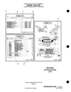
Each illustrated figure is keyed to a group-assembly parts list. The figure number appears once at the start of the list; remaining index numbers are dashed. Indentation in the description column shows assembly relationship. Attaching parts sit directly under the item they fasten, marked Attaching Parts and closed with a separator. Units Per Assembly is the quantity used per figure; attaching-part quantities are for one item and must be multiplied when more than one assembly is installed.
USABLE ON letter codes occupy the right-hand column and apply only to the figure on which they appear. Codes and the serials they cover are printed at the end of that figure. A first-column listing with no code is used on all models and serials in the catalog. An indented listing with no code is used on all models and serials covered by that figure. Bold-face serial blocks flag large production groups.
When a later part is fully interchangeable, both numbers are serialized and the earlier item carries When Exhausted Use (WEU). Non-interchangeable parts are listed separately with their own usable-on letters. NP marks items that are not procurable. AR marks bulk quantity. Standard hardware uses Cessna S-prefix standards plus AN and NAS numbers. Corrosion-proofed orders add the letters CO after the part number. Accessory kits are directed to a separate Accessory Kit and Service Kit Index rather than this catalog. Avionics, autopilot, communications, and navigation breakdowns are pointed to the Customer Care Supplies Catalog and supplier publications, not duplicated here.
Chapters Covered
- General information — title page, manufacturer’s introduction, record of revisions, record of temporary revisions, letter of transmittal, list of effective pages
- Alphabetical index and numerical index
- Finish and trim plate interpretation (1978–1980 and 1981-and-on formats)
- Paint code charts by model year (1978 through 1986)
- Upholstery and interior trim; how to order upholstered, painted, and plastic interior parts
- Miscellaneous bulk items (Fig 1)
- Registration markings (Fig 2)
- Placards, nameplates, and exterior markings (Fig 3)
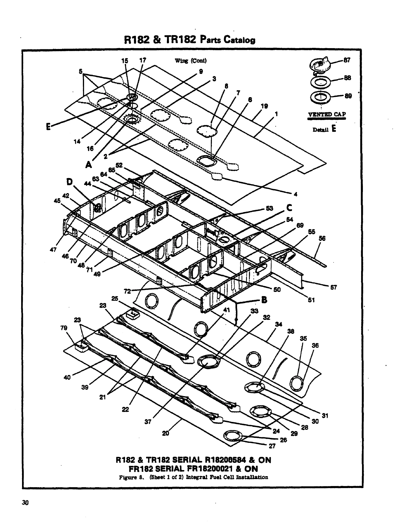
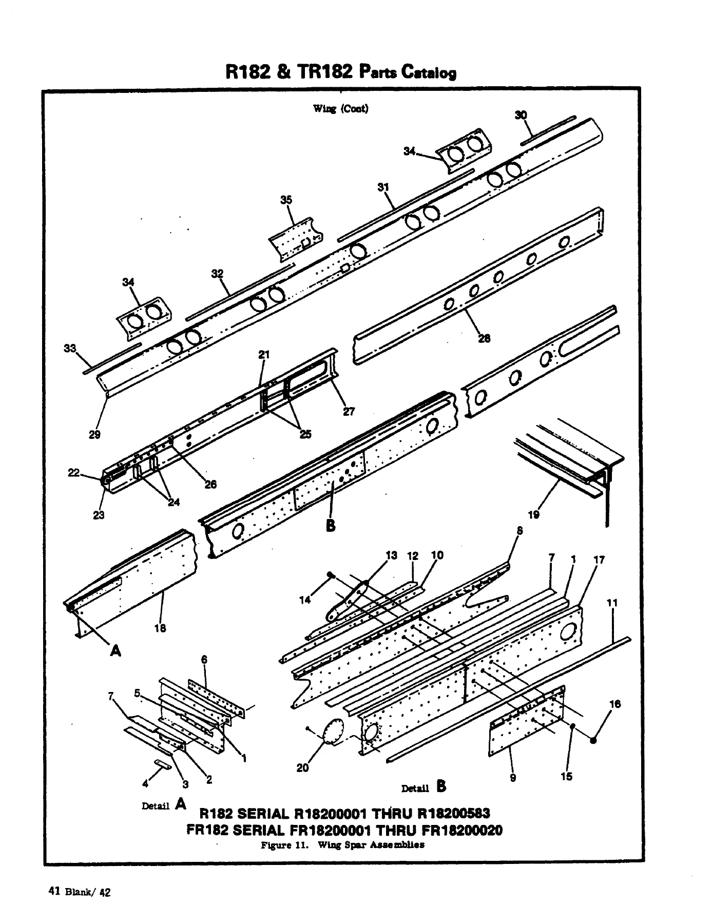
- Wing assembly complete; wing structure; integral fuel cell; leading edge; wing spars; skins and stringers (Fig 4–14)
- Fuel tank and fuel tank drain valve (Fig 15–16)
- Aileron and flap installation (Fig 17–18)
- Wing strut (Fig 19)
- Fin and dorsal, including VHF comm antenna version; rudder; stabilizer; elevator (Fig 20–24)
- Fuselage assembly, forward and lower forward structure, front doorpost bulkhead, console structure, firewall and firewall grommets (Fig 25–35)
- Center cabin, floorboard, lower cabin, fuselage center belly (Fig 36–39)
- Landing gear and rear doorpost bulkhead; main gear actuator bulkhead; main landing-gear wheel well (Fig 40–42)
- Windshield and aft cabin windows; tailcone and aft tailcone stringers (Fig 43–48)
- Nose gear, steering, shock strut; Cleveland and McCauley nose wheel and tire; shimmy dampener (Fig 49–55)
- Main landing gear, downlock, main wheel and brake; nose gear doors and actuator (Fig 56–59)
- Left and right cabin doors, RH openable window, door latch, baggage door, door upholstery (Fig 60–70)
- Cabin top, upper cabin, side and floorboard upholstery; air conditioning ducting; soundproofing (Fig 71–76)
- Pilot and copilot seats (standard and infinite-adjust), rear seat, auxiliary seat (Fig 77–83)
- Instrument panel equipment, stationary panel structure, post-lighted panel, map compartment (Fig 84–92)
- Fuselage equipment; seat belts and shoulder harness; inertia reel; seat-back table; step and handle; rear-view mirror and compass (Fig 93–98)
- Ice detector light; windshield anti-ice; propeller de-ice (two- and three-blade); propeller and spinner (Fig 99–104)
- Upper cowl and nose cap; cowl flap control; winterization equipment (Fig 105–109)
- Engine installation and engine assembly; exhaust; baffles; carburetor airbox and turbocharged heat airbox; turbocharger; throttle and wastegate controls (Fig 110–125)
- Cabin ventilation; cabin heating and defrosting (Fig 126–127)
- Brake system, brake and rudder pedals, master brake cylinder (Fig 128–131)
- Control column, control wheel and switches, console and controls (Fig 132–136)
- Aileron, electric flap, elevator, elevator trim (manual and electric), trim-tab actuator, rudder controls (Fig 137–145)
- Pitot system; encoding altimeter; blind encoder (Fig 146–148)
- Fuel system, selector valve, strainer and drain control, primer and electric primer (Fig 149–154A)
- Vacuum system including electrically driven vacuum (Fig 155–156C)
- Landing-gear hydraulic system, selector valve and lines, hydraulic power pack, emergency hand pump, nose and main gear actuators, downlock actuator, gear selector valve (Fig 157–166)
- Oxygen system (Fig 167–168)
- Electrical equipment, glareshield and panel lighting, landing lights, courtesy light, flashing beacon, console cover lighting (Fig 169–177)
- External power receptacle; alternator and 95 amp alternator; dome light; battery box and battery (Fig 178–186)
Taken together, the figures give a technician a complete illustrated breakdown of the retractable-gear Skylane RG airframe and its installed systems. You can move from a complete wing or fuselage assembly down through structure, skins, fuel cells, flight controls, cabin furnishings, engine installation, turbocharger hardware on TR182 airplanes, hydraulic landing gear, and electrical components, then pull the exact part number and the serial block that uses it.
Finish, Paint, and Interior Ordering
The Finish and Trim plate sits on the left lower door jamb below the aircraft identification nameplate. For 1978 through 1980 the stamp encodes model year, interior color scheme, optional black carpet, overall exterior color, major stripe, and accent stripe. From 1981 on the plate encodes year plus exterior overall, major stripe, and accent colors. Special paint or interior is marked SP. Year-by-year paint code charts list interior vinyl, fabric, and leather schemes against Cessna CES1054 lacquer and vinyl numbers, and exterior modified-urethane colors with CES1054 (and later CSF5052) numbers plus DuPont Imron or Pratt & Lambert cross-references where printed. Lacquer notes apply to French-built aircraft only on the early charts.
Upholstered parts marked with a number sign take a second dash for color and material on 1978–1980 airplanes: add the year code and interior color code from the Finish and Trim plate to the catalog part number. From 1981 on, those marked parts are ordered with the aircraft serial number. Interior painted or plastic parts marked with a square take a second dash from the model-year color table keyed to the interior code. The catalog prints those tables for 1978, 1979, and 1980 interiors (baggage-door panels, escutcheons, console covers, headliner tiaras, window mouldings, armrests, and related trim).
Powerplant, Gear, and Systems Content
Engine figures cover installation and assembly, exhaust (including turbocharged left-hand exhaust on TR182), baffles, carburetor airbox, turbocharger heat airbox, turbocharger, throttle control, and wastegate control. A governor note sends overhaul detail to the applicable Lycoming manual rather than expanding engine internals here. Propeller listings include two-blade and three-blade installations plus de-ice. Retractable landing gear is broken out as nose gear, steering, shock strut, Cleveland and alternate McCauley nose wheel and tire, shimmy dampener, main gear, downlock, wheels and brakes, gear doors, and the full hydraulic circuit: selector valve and lines, power pack, emergency hand pump, nose actuator, main rotary actuator, downlock actuator, and gear selector valve.
Fuel coverage runs from integral wing cells and tank drain valves through selector valve, strainer, drain control, and both manual and electric primers. Flight-control figures list aileron, electric flap, elevator, manual and electric trim, trim-tab actuator, and rudder systems. Cabin systems include ventilation, heating and defrosting, air-conditioning ducting, soundproofing, seats, belts, inertia reels, and oxygen. Electrical figures run from panel equipment and lighting through landing lights, courtesy light, flashing beacon, external power, alternator (including the 95 amp installation), and battery support.
Using the Catalog to Order
The introduction tells the reader to order from the catalog using Cessna Parts and Accessories order forms, quoting part number and name exactly as listed, with model and serial number of the airplane. Color-sensitive items follow the Upholstery and Interior Trim section. Retail factory orders are not honored; they are to be placed with a Cessna Service Station or Distributor. Bulk items such as hose, rubber mouldings, channels, and windshield sealing strips are supplied in convenient bulk length, with cut length per installation noted so the station can issue the correct amount. Cessna reserves the right to cancel, add, or change parts without notice. Inspection intervals and life limits in Cessna maintenance data apply only to Cessna-approved parts; STC installations must follow the STC holder’s inspection program. This parts catalog does not replace a service or overhaul manual and does not list supplier internal breakdowns for every vendor component.
Identify the Correct Part Before You Order
The Cessna Skylane RG R182 TR182 1978 thru 1986 Illustrated Parts Catalog supports parts research and ordering for Skylane RG and Turbo Skylane RG airframes across the printed 1978–1986 serial blocks, including Reims FR182 airplanes through FR18200070. Use the exploded figures and usable-on codes to separate standard-range and extended-range wings, early versus later interiors, two-blade versus three-blade propeller hardware, naturally aspirated versus turbocharged engine-bay parts, and serial-specific landing-gear and electrical differences. Ordering the number that matches the airplane serial avoids mixing non-interchangeable designs and documents WEU supersedures when an earlier part is exhausted.
Correct figure, index, and serial coding matter because many R182 and TR182 parts look similar across model years but are listed against different usable-on letters. The catalog is the reference for matching Cessna part numbers, attaching hardware, paint codes, and interior dash numbers to a specific airplane. Instant PDF delivery after payment — no shipping wait — so you can open the file on any device and print the figure you need at the bench or in the hangar.
Reviews
There are no reviews yet.