
Piper PA-23-250 Aztec and PA-23-235 Apache Illustrated Parts Catalog 753 522
Original price was: $31.95.$18.95Current price is: $18.95.
Illustrated Piper parts catalog 753 522 for PA-23-250 Aztec and PA-23-235 Apache airplanes, revised January 10, 2009, with figure-indexed replacement parts by serial number.
Description
Piper PA-23-250 Aztec and PA-23-235 Apache Illustrated Parts Catalog 753 522
This download is the Piper Aircraft Corporation illustrated parts catalog issued for replacement-part identification on the PA-23-250 Aztec, the PA-23-250 six-place Aztec, and the PA-23-235 Apache. The catalog carries Piper part number 753 522, was first issued August 15, 1972, and is revised through January 10, 2009. Use it to match a visible assembly on the airframe to a figure index number, then to the listed Piper part number, nomenclature, quantity, and serial-number effectivity. The introduction states that under no circumstances shall this catalog be used for rigging and installation purposes.
File Details
- Manual type: Illustrated parts catalog
- Brand / models: Piper PA-23-235 Apache, PA-23-250 Aztec, PA-23-250 (Six Place) Aztec
- Document number: 753 522
- First issued: August 15, 1972
- Revision date: January 10, 2009
- Language: English
- Page count: 684
- File format: PDF
- Manufacturer listed: Piper Aircraft Corporation, Lock Haven, Pennsylvania
Airplanes and Serial Effectivity
The Piper PA-23-250 Aztec and PA-23-235 Apache Illustrated Parts Catalog 753 522 applies part numbers by airplane serial number. Keep the serial block in mind before you order:
- 1960 Aztec PA-23-250: serials 27-1 through 27-366
- 1961 Aztec PA-23-250: serials 27-367 through 27-504
- Apache PA-23-235: serials 27-505 through 27-622
- Aztec PA-23-250 (Six Place) Model B: serials 27-2000 through 27-2504
- Aztec PA-23-250 (Six Place) Model C: serials 27-2505 through 27-3836 and 27-3838 through 27-3943
- Aztec PA-23-250 (Six Place) Model D: serials 27-3837, 27-3944 through 27-4425, and 27-4427 through 27-4573
- Aztec PA-23-250 (Six Place) Model E: serials 27-4426 and 27-4574 through 27-7554168
- Aztec PA-23-250 (Six Place) Model F: serials 27-7654001 and up
Letter codes in the parts lists further restrict usage. X marks PA-23-250 only, Y marks the six-place Aztec, and Z marks the PA-23-235 Apache. Additional letter notes call out kits already installed, 14-volt versus 28-volt electrical systems, turbocharged versus naturally aspirated powerplants, and color or vendor options.
How the Listings Are Arranged
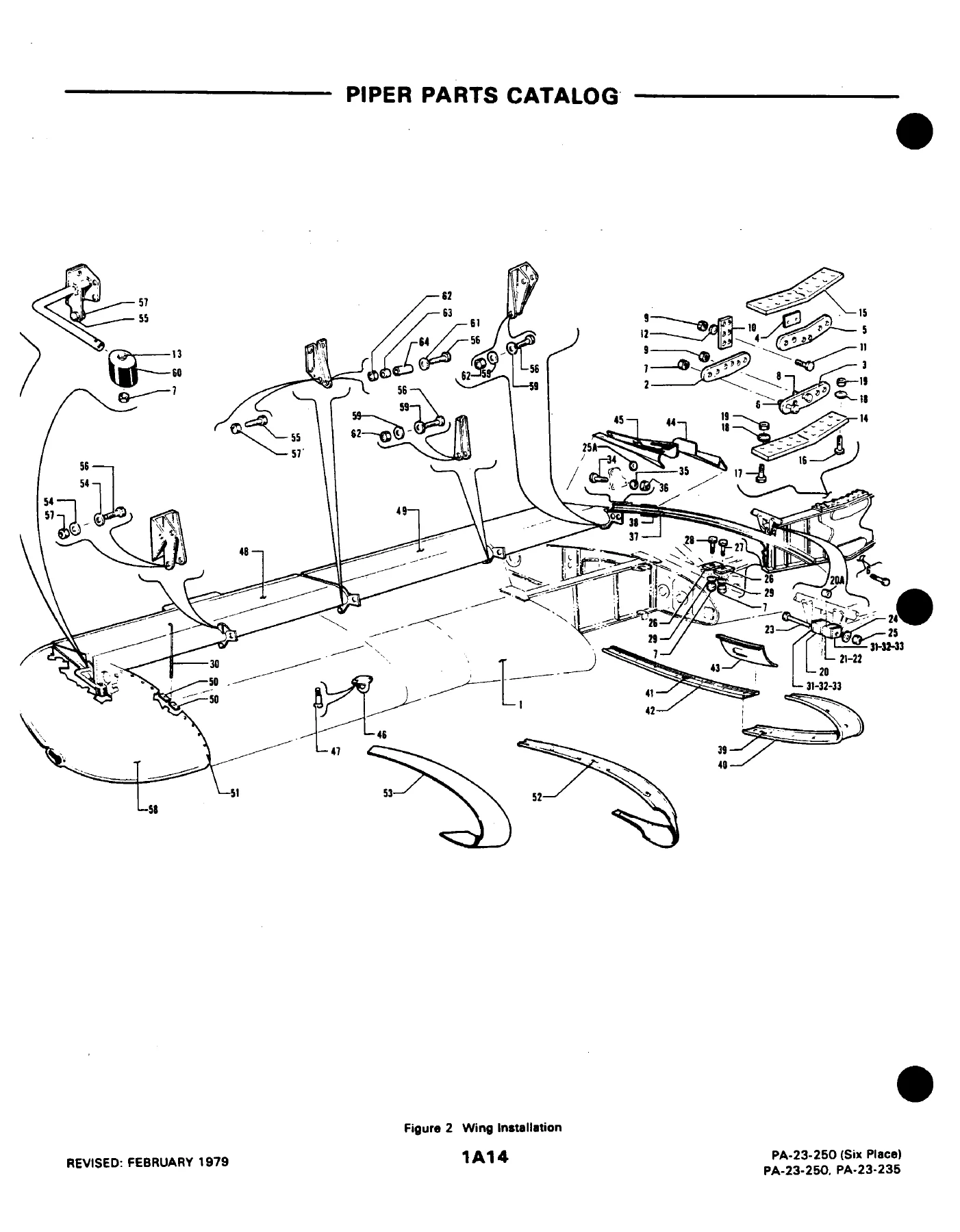
Each illustrated group opens with an exploded view. The facing parts list uses six columns: figure and index number, part number, code, nomenclature, number required, and serial numbers affected. Indentation and asterisks show next-higher-assembly relationships. Order the top-level assembly and you receive the indented items; order a single indented item and you receive only that piece. Commercial attaching hardware such as AN bolts and MS nuts is listed after the part name for convenience, even though Piper generally does not stock those items as catalog merchandise.
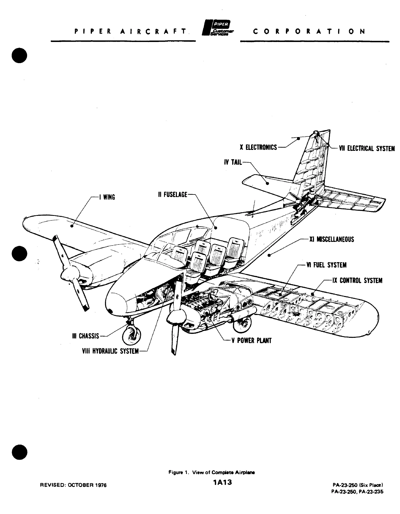
The catalog also explains how to work from a part you can see: start with Figure 1 (complete airplane) to pick the major group, open the matching figure, read the index number off the drawing, then read the full line in the parts list. Orders must include model, serial number, part number, name, type, and quantity.
Limitations printed in the catalog
On PA-23-250 six-place airplanes serial 27-7954061 and up, replacement parts for optional avionics and electronics installations (radar, radio altimeter, encoding altimeter, and similar equipment) are not listed or illustrated. On serial 27-8054001 and up, optional autopilot parts are likewise omitted. For those airplanes the catalog directs you to the avionics drawing index list and the drawings supplied with the aircraft. The cover also identifies this issue as Card 1 of 3 in the original card-set format; the compiled file presented here runs through Section XI and the numerical index.
Chapters Covered
- Introduction, revisions status, serial-number information, standard paint chart, and table of contents
- Figure 1 — View of complete airplane
- Section I Wing Group — Wing installation; flap and aileron assemblies; wing and wing-tip construction; wing and wing-tip skin
- Section II Fuselage Group — Complete fuselage; forward, center, and aft sections; bottom fairing; fuselage frame; instrument panel installations (single and dual, by serial block); control pedestal; floorboard and cockpit finishing; window curtains; enclosure; baggage and cabin doors; oxygen systems; seats; vacuum pumps; airspeed, static, oil-pressure and manifold-pressure lines; ventilating systems; Stewart Warner and Janitrol heater assemblies
- Section III Chassis Group — Gear strut assemblies; nose gear and nose wheel; main gear and main wheel; brake and dual-brake installations; brake assembly
- Section IV Tail Surfaces Group — Tail surfaces installation; stabilator assemblies by serial block; rudder assembly; fin assembly
- Section V Power Plant Group — Power-plant installation by serial block; AiResearch and Lycoming turbocharger installations; propellers; propeller synchronizer and synchrophaser systems; engine baffles; exhaust collectors and exhaust system; nacelle installations including the Lycoming-turbocharger nacelle
- Section VI Fuel System Group — Fuel system and fuel-injection installations; fuel cells; wing-tip fuel tanks; fuel-system control boxes
- Section VII Electrical System Group — Fuselage and wing electrical installations; 14-volt and 28-volt battery boxes; pedestal and instrument-panel electrical installations; taxi and strobe lights; external power supply; propeller deicers; pneumatic deicers (B.F. Goodrich and Airborne/Goodyear)
- Section VIII Hydraulic System Group — Hydraulic system and component installations; landing-gear anti-retraction valve; hydraulic powerpak components; emergency gear extender
- Section IX Control System Group — Engine controls; stabilator, aileron, and rudder controls; tail-trim mechanism; trim-tab interconnect
- Section X Electronics Group — Collins and ARC radios; radio junction boxes (14-volt and 28-volt); all-weather antenna; ELT installations (Garrett, Communications Components Corp., Narco); marker beacon; AutoControl I/II/III/III B; AltiMatic I through V and related flight-director installations; Bendix FCS-810; King KAP-200 / KFC-200; radar altimeter; glide-slope coupler; RMI; King KWX-40 and Bendix RDR-150 radar; encoding altimeter; radio installation and wiring-diagram drawing list
- Section XI Miscellaneous Group — Optional equipment kits, repair kits and special tools; decals
- Numerical index of part numbers to figure and index numbers
Taken as a whole, the Piper PA-23-250 Aztec and PA-23-235 Apache Illustrated Parts Catalog 753 522 is a parts-identification book rather than a workshop procedure manual. A technician uses the figures and serial-coded lists to decide which wing panel, flap hinge, nacelle cowl, fuel cell, powerpak component, or radio junction box belongs on a given serial number, then places the order with the correct Piper number and nomenclature.
Powerplant and Related Hardware Called Out in the Lists
Power Plant Group listings name the engines and turbocharger packages that change part effectivity. Engines called out include Lycoming O-540-A1B5 250 H.P., Lycoming O-540-A1D5 250 H.P., Lycoming IO-540-C4B5, Lycoming IO-540-J4A5, and Lycoming TIO-540-C1A. Separate figures cover AiResearch turbocharger installation, Lycoming turbocharger installation, early and late propellers, propeller synchronizer and synchrophaser hardware, baffles, exhaust collectors, and the distinct nacelle used with the Lycoming turbocharger. Fuel-system figures split carbureted installations, fuel-injection installations from serial 27-2322 through 27-2504, later six-place fuel systems, fuel cells through serial 27-4815 versus 27-4816 and up, and wing-tip tanks from serial 27-7654001 and up.
Airframe, Landing Gear, and Cabin Hardware
Wing Group figures identify left and right wing panel assemblies that change across Apache, early Aztec, and six-place production, plus spar straps, shims, root fairings, tie-down rings, ailerons, flaps, and wing tips. Fuselage Group figures run from the complete shell through serial-specific instrument panels, dual pitot-static hardware, seats, doors, oxygen bottles and regulators, Stewart Warner and Janitrol heaters, and ventilating ducting. Chassis Group figures cover nose and main gear struts, wheels, and single or dual brake installations. Tail figures separate the stabilator used through serial 27-7554168 and 27-8054001 and up from the stabilator used on serials 27-7654001 through 27-7954121, plus rudder and fin.
Electrical, Hydraulic, Ice Protection, and Paint
Electrical listings distinguish 14-volt and 28-volt battery boxes, with a further 28-volt split at serial 27-7954098. External power, taxi lights, strobes, propeller deicers, and pneumatic deicer boots from B.F. Goodrich and Airborne/Goodyear appear in their own figures. Hydraulic figures cover the early combined system, the later split fuselage and wing systems, powerpak internals, the anti-retraction valve, and the emergency gear extender through serial 27-7954121. A standard paint chart lists exterior enamel, acrylic lacquer, and Titanine polyurethane colors with quart and gallon Piper numbers, plus interior thermoplastic-trim aerosol colors.
Ordering From This Catalog
When you work from the Piper PA-23-250 Aztec and PA-23-235 Apache Illustrated Parts Catalog 753 522, specify model and serial number on every order, then the part number and the nomenclature exactly as printed. Shortages must be claimed within three days of receipt. Returned goods require prior written permission and prepaid freight. Damage in transit is a carrier claim. Those administrative notes sit in the front matter alongside the grid-numbering explanation left over from the Aerofiche card set.
What This Catalog Lets You Do
With the Piper PA-23-250 Aztec and PA-23-235 Apache Illustrated Parts Catalog 753 522 you can identify wing panels, flaps, ailerons, fuselage skins and frames, instrument panels, seats, doors, oxygen and heater components, landing-gear and brake parts, tail surfaces, engines and turbocharger hardware, propellers, fuel cells and selector boxes, electrical boxes and lighting, hydraulic powerpak pieces, flight-control cables and trim hardware, and the radios and autopilots that the catalog still illustrates for earlier serials. Matching the printed serial range and letter code to the airplane on the ramp keeps you from ordering a six-place-only panel for an Apache or a pre-4816 fuel cell for a later wing. Instant PDF delivery after payment means you can open the figures on any device and print the pages you need in the hangar—no shipping wait.
Reviews
There are no reviews yet.