★ TRUSTED BY 321,897+ PROFESSIONALS WORLDWIDE
🏢
Trusted Business
Verified & Licensed
🛡️
Virus Free Files
100% Safe Downloads
🔒
Secure Payment
SSL Protected
Instant Delivery
Available Immediately
Sale!

Piper PA-31P Pressurized Navajo Illustrated Parts Catalog 1970-1977 PDF

Original price was: $34.95.Current price is: $19.95.

Piper Aircraft PA-31P Pressurized Navajo illustrated parts catalog (P/N 753 769, revised September 10, 2009) covering 1970–1977 serials from 31P-3 through 31P-7730012, with exploded views, part numbers, quantities, and serial effectivity for airframe, power plant, systems, and kits.

Instant PDF Download
Available immediately
💾
Save to Your Device
Download & keep forever
🛡️
Antivirus Scanned
100% virus-free
🌍
Trusted Worldwide
175,000+ customers

Description

File Details

  • Manual type: Illustrated Parts Catalog
  • Aircraft: Piper Model PA-31P Pressurized Navajo
  • Language: English
  • Page count: 554
  • File format: PDF
  • Document number: 753 769
  • Original issue: December 18, 1972
  • Revision in this file: September 10, 2009 (PR090910)

The Piper PA-31P Pressurized Navajo Illustrated Parts Catalog 1970-1977 PDF is the illustrated replacement-parts reference compiled by Piper Aircraft Corporation of Lock Haven, Pennsylvania for the pressurized twin. Each illustrated group is paired with a parts list that gives Piper part number, nomenclature, quantity required, letter codes for special use, and the serial numbers to which that item applies.

Aircraft and Serial Coverage

Use this catalog only for the PA-31P Pressurized Navajo serials printed in the serial-number section:

  • 1970 models: 31P-3 to 31P-30 inclusive
  • 1971 models: 31P-31 to 31P-66 inclusive
  • 1972 models: 31P-67 to 31P-109 inclusive
  • 1973 models: 31P-7300110 to 31P-7300172 inclusive
  • 1974 models: 31P-7400173 to 31P-7400230 inclusive
  • 1975 models: 31P-7530001 to 31P-7530028 inclusive
  • 1976 models: 31P-7630001 to 31P-7630019 inclusive
  • 1977 models: 31P-7730001 to 31P-7730012 inclusive

The same pages explain how the manufacturer’s identification plate is built: a two-number set for 1970–1972 (type certificate plus sequence), a three-number set for 1973–1974 (type, model year, sequence), and a four-number set from 1975 onward (type, model year, model code, sequence within the year). Orders must include model and serial number together with part number, name, type, and quantity.

How the Parts Lists Work

Figure-and-index numbers tie every line to a callout on the facing illustration. Indentation with asterisks shows next-higher assembly: ordering an undented door assembly includes the latch tube and its clevis and clip; ordering only the clevis brings that piece alone. The No. Req. column is aircraft quantity for a top-level item and assembly quantity for an indented item; AR means as required. Attaching hardware that is commercial stock is listed for convenience with its AN/MS identity after the name. Optional equipment is mixed into the same lists and identified by description rather than a separate optional flag. The catalog states plainly that it must not be used for rigging or installation.

Complete PDF Bookmark Tree

Complete Bookmarks

The complete bookmarks in the “Piper PA-31P Pressurized Navajo Illustrated Parts Catalog 1970-1977 PDF” are as follows:

753-769 – PRESSURIZED NAVAJO PARTS CATALOG – PA-31Pp. 1
AEROFICHE EXPLANATION AND REVISION STATUSp. 2
INTRODUCTIONp. 3
TABLE OF CONTENTSp. 8
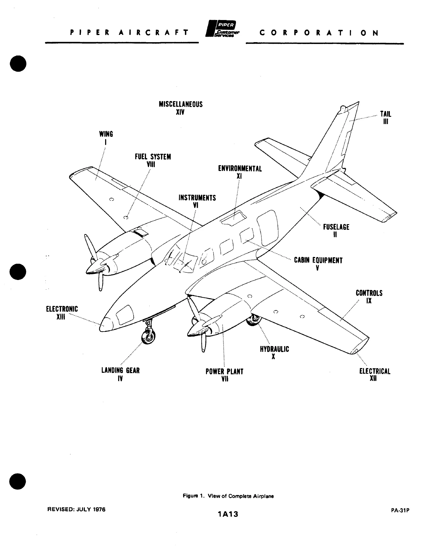
FIGURE 1. VIEW OF COMPLETE AIRPLANEp. 13
SECTION I – WING SECTIONp. 14
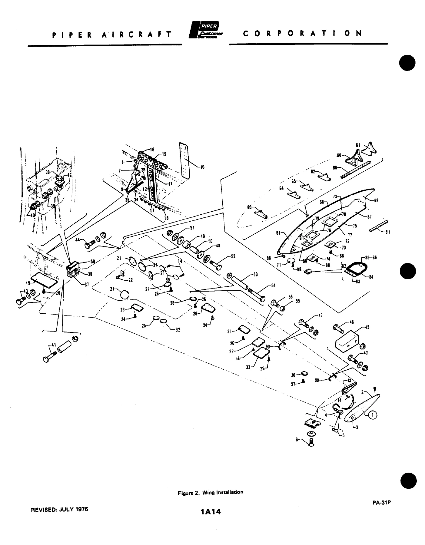
FIGURE 2. WING INSTALLATIONp. 14
FIGURE 3. WING PANEL INBOARD PARTS INSTALLATIONp. 19
FIGURE 4. WING PANEL OUTBOARD PARTS INSTALLATIONp. 21
FIGURE 5. WING PANEL LEADING EDGE ASSEMBLYp. 25
FIGURE 6. LEADING EDGE SPAR ASSEMBLYp. 28
FIGURE 7. WING PANEL REAR SPAR ASSEMBLYp. 31
FIGURE 8. AILERON ASSEMBLYp. 37
FIGURE 9. FLAP ASSEMBLYp. 40
SECTION II – FUSELAGEp. 43
FIGURE 10. FUSELAGE ASSEMBLYp. 43
FIGURE 11. UPPER FORWARD SECTION ASSEMBLYp. 45
FIGURE 12. UPPER CABIN SECTION ASSEMBLYp. 49
FIGURE 13. LOWER FORWARD SECTION ASSEMBLYp. 53
FIGURE 14. LOWER FORWARD FRAME ASSEMBLYp. 56
FIGURE 15. PRESSURE BULKHEAD ASSEMBLYp. 60
FIGURE 16. LOWER REAR SECTION ASSEMBLYp. 62
FIGURE 17. LOWER CENTER FRAME ASSEMBLYp. 66
FIGURE 18. LOWER REAR FRAME ASSEMBLYp. 69
FIGURE 19. AFT SECTIONp. 73
FIGURE 20. STRUCTURE INSTALLATION, STA. 375 TO STA. 215p. 78
FIGURE 21. STRUCTURE INSTALLATION, STA. 215 TO STA. 244p. 81
FIGURE 22. INNER SKIN INSTALLATIONp. 83
FIGURE 23. FLOORBOARD INSTALLATIONp. 85
FIGURE 24. WINDSHIELD INSTALLATIONp. 88
FIGURE 25. WINDOWS INSTALLATION (EXTERNAL)p. 90
FIGURE 26. EMERGENCY EXIT WINDOW INSTALLATION (S/N 31P-3 TO 31P-109 INCL)p. 92
FIGURE 26A. EMERGENCY EXIT WINDOW INSTALLATION (S/N 31P-7300110 AND UP)p. 94
FIGURE 26B. OVERHEAD WINDOW INSTALLATION (S/N 31P-7400178 TO 31P-7630019 INCL)p. 97
FIGURE 27. NOSE CONE INSTALLATIONp. 99
FIGURE 28. CABIN ENTRANCE DOOR INSTALLATIONp. 102
FIGURE 28A. CABIN ENTRANCE DOOR ASSEMBLYp. 106
FIGURE 29. CABIN DOOR LATCH INSTALLATIONp. 108
FIGURE 30. CABIN DOOR STEP INSTALLATIONp. 111
FIGURE 31. CABIN DOOR SNUBBER INSTALLATIONp. 114
FIGURE 32. CABIN DOOR INFLATION SYSTEM INSTALLATIONp. 116
FIGURE 33. FORWARD BAGGAGE DOOR INSTALLATIONp. 118
SECTION III – TAIL SURFACESp. 121
FIGURE 34. TAIL SURFACE INSTALLATIONp. 121
FIGURE 35. FIN ASSEMBLYp. 125
FIGURE 36. RUDDER ASSEMBLYp. 127
FIGURE 37. STABILIZER ASSEMBLYp. 130
FIGURE 38. ELEVATOR ASSEMBLYp. 132
SECTION IV – LANDING GEARp. 136
FIGURE 39. MAIN LANDING GEAR INSTALLATIONp. 136
FIGURE 40. MAIN GEAR STRUT ASSEMBLYp. 140
FIGURE 41. MAIN WHEEL ASSEMBLYp. 143
FIGURE 42. MAIN WHEEL BRAKE ASSEMBLYp. 145
FIGURE 43. NOSE LANDING GEAR INSTALLATIONp. 147
FIGURE 44. NOSE GEAR STRUT ASSEMBLYp. 151
FIGURE 45. NOSE WHEEL ASSEMBLYp. 154
FIGURE 46. NOSE GEAR STEERING INSTALLATIONp. 156
FIGURE 47. BRAKE SYSTEM INSTALLATIONp. 159
FIGURE 48. DUAL BRAKE INSTALLATIONp. 162
FIGURE 49. MASTER CYLINDER AND PARKING BRAKE VALVEp. 164
FIGURE 50. LANDING GEAR SELECTOR MECHANISM INSTALLATIONp. 166
SECTION V – CABIN EQUIPMENTp. 169
FIGURE 51. CABIN INTERIOR FINISHING INSTALLATION (31P-3 TO 31P-7630005 INCL)p. 169
FIGURE 51A. CABIN INTERIOR FINISHING INSTALLATION (3 P-7630006 AND UP)p. 175
FIGURE 52. INTERIOR WINDOWS AND CURTAINS INSTALLATIONp. 178
FIGURE 53. CABIN HEADLINER INSTALLATION (31P-3 TO 31P-7630019 INCL)p. 181
FIGURE 53A. CABIN HEADLINER INSTALLATION (S/N 31P-7730001 AND UP)p. 184
FIGURE 54. CARPET INSTALLATIONp. 186
FIGURE 55. CREW SEATS INSTALLATIONp. 191
FIGURE 56. PASSENGER SEATS INSTALLATIONp. 197
FIGURE 57. 7TH SEAT INSTALLATIONp. 204
FIGURE 58. 8TH SEAT INSTALLATIONp. 209
FIGURE 59. TOILET SEAT INSTALLATIONp. 215
FIGURE 60. FORWARD CABIN DIVIDER, FIRE EXTINGUISHER AND STORAGE CABINET INSTALLATION (31P-3 TO 31P-7630005 INCLUSIVEp. 219
FIGURE 60A. FORWARD CABIN DIVIDER AND STORAGE CABINET INSTALLATION (31 P-7630006 AND UPp. 222
FIGURE 62. REAR DIVIDER PANEL AND BEVERAGE DISPENSER INSTALLATIONp. 226
FIGURE 61. FOLDING TABLE AND REFRESHMENT CABINET INSTALLATIONp. 224
FIGURE 63. BAGGAGE COMPARTMENTS FINISHING INSTALLATIONp. 228
SECTION VI – INSTRUMENTSp. 231
FIGURE 64. INSTRUMENT PANEL INSTALLATIONp. 231
FIGURE 65. DUAL INSTRUMENT PANEL INSTALLATIONp. 239
FIGURE 66. TRUE AIRSPEED INDICATOR INSTALLATION (31P-3 TO 31P-7530028 INCL)p. 242
FIGURE 67. MISCELLANEOUS AIR AND FLUID LINES INSTALLATIONp. 244
FIGURE 68. STATIC AIR SYSTEM INSTALLATIONp. 247
FIGURE 69. GYRO INSTRUMENT LINES INSTALLATIONp. 250
FIGURE 70. DUAL INSTRUMENT AIR SYSTEM INSTALLATIONp. 252
SECTION VII – POWER PLANTp. 254
FIGURE 71. POWER PLANT INSTALLATIONp. 254
FIGURE 72. ENGINE BAFFLE INSTALLATIONp. 258
FIGURE 73. CYLINDER HEAD BAFFLE INSTALLATIONp. 260
FIGURE 74. ENGINE CONTROLS INSTALLATIONp. 263
FIGURE 75. ENGINE COWL INSTALLATIONp. 266
FIGURE 76. COWL FLAP ACTUATING MECHANISM INSTALLATIONp. 269
FIGURE 77. NACELLE INSTALLATIONp. 271
FIGURE 78. OIL COOLER INSTALLATIONp. 275
FIGURE 79. PROPELLER ASSEMBLYp. 277
FIGURE 79A. PROPELLER SYNCHRONIZER SYSTEM INSTALLATIONp. 280
FIGURE 79B. PROPELLER SYNCHROPHASER SYSTEM INSTALLATIONp. 282
SECTION VIII – FUEL SYSTEMSp. 290
FIGURE 80. FUEL CONTROL PANEL INSTALLATIONp. 290
FIGURE 81. LEFT ENGINE FUEL SYSTEM INSTALLATIONp. 293
FIGURE 82. RIGHT ENGINE FUEL SYSTEM INSTALLATIONp. 298
FIGURE 83. AUXILIARY FUEL LINES INSTALLATIONp. 303
FIGURE 84. FUEL SYSTEM COMPONENTSp. 306
FIGURE 85. FUEL FLOW GAUGE INSTALLATIONp. 309
FIGURE 86. MAIN FUEL CELL AND LINER INSTALLATIONp. 311
FIGURE 87. NACELLE AND AUXILIARY FUEL CELL AND LINER INSTALLATIONp. 314
SECTION IX – CONTROLSp. 317
FIGURE 88. PEDESTAL INSTALLATIONp. 317
FIGURE 89. PEDESTAL CONTROL ASSEMBLYp. 322
FIGURE 90. AILERON CONTROL INSTALLATIONp. 325
FIGURE 91. AILERON TRIM INSTALLATIONp. 328
FIGURE 92. RUDDER CONTROL INSTALLATIONp. 333
FIGURE 93. RUDDER TRIM INSTALLATIONp. 336
FIGURE 94. ELEVATOR CONTROL INSTALLATIONp. 339
FIGURE 95. ELEVATOR TRIM INSTALLATIONp. 342
FIGURE 96. FLAP CONTROL INSTALLATIONp. 345
FIGURE 97. CONTROL WHEEL INSTALLATIONp. 347
FIGURE 98. RUDDER PEDAL INSTALLATIONp. 351
SECTION X – HYDRAULIC SYSTEMSp. 354
FIGURE 99. FORWARD HYDRAULIC SYSTEM INSTALLATIONp. 354
FIGURE 100. AFT HYDRAULIC SYSTEM INSTALLATIONp. 357
FIGURE 101. HYDRAULIC PUMPS INSTALLATIONp. 359
FIGURE 102. HYDRAULIC SYSTEM COMPONENTS (OZONE)p. 362
FIGURE 102A. HYDRAULIC SYSTEM COMPONENTS (WIEBEL)p. 364
FIGURE 103. HYDRAULIC POWERPAK ASSEMBLY (OZONE)p. 367
FIGURE 103A. HYDRAULIC POWERPAK COMPONENTS (OZONE)p. 370
FIGURE 104. HYDRAULIC POWERPAK ASSEMBLY (WIEBEL)p. 372
FIGURE 104A. HYDRAULIC POWERPAK COMPONENTS (WIEBEL)p. 375
SECTION XI – ENVIRONMENTALp. 377
FIGURE 105. HEATER AND EVAPORATOR INSTALLATIONp. 377
FIGURE 106. HEATER ASSEMBLYp. 381
FIGURE 107. HEATER COMBUSTION AIR BLOWER AND MOTOR ASSEMBLYp. 383
FIGURE 108. HEATER IGNITION ASSEMBLYp. 385
FIGURE 109. CABIN PRESSURE CONTROL SYSTEM INSTALLATIONp. 387
FIGURE 110. AIR DISTRIBUTION DUCT INSTALLATIONp. 390
FIGURE 111. FUSELAGE PRESSURIZATION AIR SUPPLY INSTALLATIONp. 392
FIGURE 112. WING PRESSURIZATION AND PNEUMATIC AIR SUPPLY INSTALLATIONp. 395
FIGURE 113. OXYGEN SYSTEM INSTALLATIONp. 398
FIGURE 114. FUSELAGE FREON LINES INSTALLATIONp. 401
FIGURE 115. FREON LINES INSTALLATION – WINGp. 403
FIGURE 116. FREON CONDENSER SCOOP INSTALLATIONp. 405
FIGURE 117. WINDSHIELD DEFROSTER SYSTEM INSTALLATIONp. 407
FIGURE 118. PNEUMATIC DE-ICING SYSTEM INSTALLATIONp. 409
SECTION XII – ELECTRICAL SYSTEMp. 412
FIGURE 119. PRIMARY AND AUXILIARY POWER INSTALLATIONp. 412
FIGURE 120A. INSTRUMENT PANEL HARNESS INSTALLATIONp. 418
FIGURE 121. AFT ELECTRICAL SYSTEM INSTALLATIONp. 421
FIGURE 120. FORWARD ELECTRICAL SYSTEM INSTALLATIONp. 415
FIGURE 121A. SWITCH AND CIRCUIT BREAKERS SYSTEM INSTALLATIONp. 423
FIGURE 122. STROBE LIGHTS INSTALLATION (S/N 31P-3 TO 31P-7300146 INCL)p. 426
FIGURE 122A. STROBE LIGHTS INSTALLATION (S/N 31P-7300147 AND UP)p. 429
FIGURE 123. OVERHEAD SWITCH PANEL INSTALLATIONp. 431
FIGURE 124. LANDING LIGHT AND ICE DETECTION LIGHT INSTALLATIONp. 434
FIGURE 125. ELECTRIC WINDSHIELD WIPER INSTALLATIONp. 436
FIGURE 126. PROPELLER ELECTRIC DE-ICER INSTALLATIONp. 438
SECTION XIII – ELECTRONICS SYSTEMp. 441
FIGURE 126A. ALTIMATIC PILOT III B INSTALLATIONp. 441
FIGURE 126B. ALTIMATIC PILOT III B-1 INSTALLATIONp. 444
FIGURE 127. ALTIMATIC PILOT III C INSTALLATIONp. 447
FIGURE 127A. ALTIMATIC V F/D AND V F/D-1 AUTOPILOT INSTALLATIONp. 451
FIGURE 127B. ALTIMATIC V AND V-1 AUTOPILOT INSTALLATIONp. 455
FIGURE 127C. RADIO MAGNETIC INDICATOR INSTALLATION (USED WITH ALTIMATIC III B & ALTIMATIC III B-1)p. 458
FIGURE 127D. RADIO MAGNETIC INDICATOR INSTALLATION (USED WITH ALTIMATIC V, V-1, V F/D OR V F/D-1)p. 460
FIGURE 128. GLIDE SLOPE COUPLER INSTALLATIONp. 462
FIGURE 128A. PIPER AUTOMATIC LOCATOR (ELT) INSTALLATION (GARRETT MFG. LTD)p. 464
FIGURE 128B. PIPER AUTOMATIC LOCATOR (ELT) INSTALLATION (COMMUNICATIONS COMPONENTS CORP)p. 466
FIGURE 128C. PIPER AUTOMATIC LOCATOR (ELT) INSTALLATION (NARCO AVIONICS)p. 468
FIGURE 128D. R.C.A. RADAR INSTALLATIONp. 470
FIGURE 128E. BENDIX RADAR INSTALLATION (RDR-110) (31P-3 TO 31P-7530022 INCL)p. 472
FIGURE 129. BENDIX RADAR INSTALLATION (RDR-130)p. 475
FIGURE 129A. BENDIX RADAR INSTALLATION (RDR-140)p. 477
FIGURE 129B. BENDIX RADAR INSTALLATION (RDR-150)p. 479
FIGURE 129C. RADAR ALTIMETER INSTALLATIONp. 481
FIGURE 129D. COLLINS RADIO ALTIMETER INSTALLATIONp. 483
FIGURE 129E. ENCODING ALTIMETER AND ALTITUDE ALERTER INSTALLATIONp. 485
FIGURE 129F. RADIO TELEPHONE SYSTEM INSTALLATIONp. 487
FIGURE 130. ANTENNA CABLE, SPEAKER, STATIC WICKS, JACK AND MIKE INSTALLATIONp. 489
FIGURE 130A. RADIO JUNCTION BOX AND TRANSMITTER SELECTOR ASSEMBLIESp. 491
RADIO DRAWINGSp. 494
SECTION XIV – MISCELLANEOUSp. 499
FIGURE 131. PLACARDS AND EXTERIOR STENCILSp. 499
OPTIONAL EQUIPMENT KITS AND REPAIR KITSp. 504
NUMERICAL INDEXp. 509

Chapters Covered

  • Figure 1 — View of Complete Airplane
  • Section I Wing — wing installation; inboard and outboard panel parts; leading edge and leading-edge spar; rear spar; aileron; flap
  • Section II Fuselage — fuselage assembly; upper forward and cabin sections; lower forward section and frame; pressure bulkhead; lower rear and center frames; aft section; structure Sta. 375–215 and 215–244; inner skin; floorboard; windshield; external windows; emergency exit windows (early and 31P-7300110-and-up); overhead windows; nose cone; cabin entrance door and door assembly; latch, step, snubber, and door inflation; forward baggage door
  • Section III Tail Surfaces — tail installation; fin; rudder; stabilizer; elevator
  • Section IV Landing Gear — main gear, strut, wheel, and brake; nose gear, strut, and wheel; nose-gear steering; brake system and dual brake; master cylinder and parking-brake valve; landing-gear selector mechanism
  • Section V Cabin Equipment — interior finishing (early and later serials); interior windows and curtains; headliner (two serial groups); carpet; crew, passenger, 7th, 8th, and toilet seats; forward cabin divider with fire extinguisher or storage cabinet; folding table and refreshment cabinet; rear divider and beverage dispenser; baggage-compartment finishing
  • Section VI Instruments — instrument panel and dual panel; true airspeed indicator; miscellaneous air and fluid lines; static air; gyro instrument lines; dual instrument air
  • Section VII Power Plant — power-plant installation; engine and cylinder-head baffles; engine controls; cowl and cowl-flap mechanism; nacelle; oil cooler; propeller; propeller synchronizer and synchrophaser
  • Section VIII Fuel System — fuel control panel; left and right engine fuel systems; auxiliary fuel lines; fuel-system components; fuel-flow gauge; main fuel cell and liner; nacelle and auxiliary cells and liners
  • Section IX Controls — pedestal and pedestal control; aileron and aileron trim; rudder and rudder trim; elevator and elevator trim; flap control; control wheel; rudder pedals
  • Section X Hydraulic System — forward and aft hydraulic installations; pumps; Ozone and Wiebel components and powerpak assemblies
  • Section XI Environmental — heater and evaporator; heater assembly, combustion-air blower, and ignition; cabin pressure control; air-distribution ducts; fuselage and wing pressurization and pneumatic supply; oxygen; fuselage and wing Freon lines; Freon condenser scoop; windshield defroster; pneumatic deicing
  • Section XII Electrical System — primary and auxiliary power; forward and aft electrical; instrument-panel harness; switches and circuit breakers; strobe lights (two serial groups); overhead switch panel; landing and ice-detection lights; electric windshield wiper; propeller electric deicer
  • Section XIII Electronics System — AltiMatic III B, III B-1, III C, V, V-1, V F/D and V F/D-1; radio magnetic indicators; glide-slope coupler; Garrett, Communications Components, and Narco ELT; R.C.A. and Bendix RDR-110/130/140/150 radar; radar and Collins radio altimeters; encoding altimeter and altitude alerter; radio telephone; antennas, speakers, static wicks, jack and mike; radio junction box and transmitter selector; radio drawings
  • Section XIV Miscellaneous — placards and exterior stencils; optional equipment kits, repair kits, and special tools; numerical index

Taken together, the Piper PA-31P Pressurized Navajo Illustrated Parts Catalog 1970-1977 PDF lets a technician walk from a visible assembly on the airplane to the exact Piper number, the next-higher assembly that contains it, the hardware that holds it, and the serial break that decides which dash number is correct. That is the whole purpose of the book: positive identification of replacement parts for this pressurized Navajo, not a substitute for a service manual.

Power Plant and Related Assemblies

The power-plant group lists ENGINE ASSEMBLY – Lycoming (TIGO-541-E1A) as quantity two, with the note to secure the engine from Lycoming-Division Avco Corporation, Williamsport. Surrounding callouts cover mounts (including rear J-9612-8 and front J-7763-26 styles), baffles, throttle and propeller cables, cowl assemblies, oil-specification placards, nacelle structure, oil cooler, propeller assembly, and the later synchronizer and synchrophaser installations. Fuel pages split left and right engine systems, auxiliary lines, cells and liners, heated-vent supersedure kit 763 994, and serial-split gauge and access plates.

IMAGES PREVIEW

Piper PA-31P Pressurized Navajo Illustrated Parts Catalog 1970-1977 PDF — PDF page 1 preview
Piper PA-31P Pressurized Navajo Illustrated Parts Catalog 1970-1977 PDF — PDF page 13 preview
Piper PA-31P Pressurized Navajo Illustrated Parts Catalog 1970-1977 PDF — PDF page 14 preview

Paint Colors, Kits, and Cross-Reference

Standard paint charts list acrylic lacquer and Titanine polyurethane enamel and primer colors with manufacturer numbers and Piper quart and gallon part numbers (Juneau White, Dakota Black, Bahama Blue, Madrid Red, and the remaining catalog colors, plus thinners, catalyst, reducer, and epoxy primer/converter). Section XIV adds placards and exterior stencils plus the optional-equipment, repair-kit, and special-tool list. A numerical index at the back maps part number to figure-and-index location so a number found on a tag or packing slip can be traced back to its illustration.

Revision Trail in This File

Revisions recorded from the December 18, 1972 issue through this September 10, 2009 card include PR750314, PR760109, PR760716, PR770325, PR800512, PR840611, PR060910, PR080310, PR080910, and PR090910. Individual figure pages also carry their own revision dates and frequent notes to the latest Piper Service Bulletin or Service Letter that affects a part. Where a listing is superseded, the catalog names the replacement kit (examples in the file include heated fuel vent kit 763 994 and several door, vent, and ELT kits).

Identify the Correct PA-31P Part Before You Order

With the Piper PA-31P Pressurized Navajo Illustrated Parts Catalog 1970-1977 PDF open, a shop can confirm wing-tip light assemblies by serial (navigation-only versus navigation-and-strobe), choose the matching cabin-door, window, interior-finish, or headliner group for an early versus later airplane, separate Ozone from Wiebel hydraulic powerpak pieces, and pick the AltiMatic, radar, or ELT installation that was actually fitted. Wrong dash numbers are expensive on a pressurized twin; matching figure, index, part number, and serial column is how this catalog prevents that mistake.

Correct identification matters because many PA-31P items change at documented serial breaks—wing panels, fuel vents, emergency-exit windows, strobe lights, instrument panels, and interior kits among them. Using the printed effectivity instead of a look-alike number from another Navajo variant keeps the order aligned with the airframe on the ramp.

Delivery is an instant PDF download after payment. There is no printed-book shipping delay. Open the file on a desktop, tablet, or phone in the hangar and print the figure and parts-list pages you need for a work order or parts request.
Reviews

There are no reviews yet.

Be the first to review “Piper PA-31P Pressurized Navajo Illustrated Parts Catalog 1970-1977 PDF”

What Our Customers Say

★★★★★ Live reviews from customers
Loading customer reviews...
0
    0
    Your Cart
    Your cart is emptyReturn to Shop
    🛒
    Recently Purchased
    🕒 verified order