★ TRUSTED BY 321,897+ PROFESSIONALS WORLDWIDE
🏢
Trusted Business
Verified & Licensed
🛡️
Virus Free Files
100% Safe Downloads
🔒
Secure Payment
SSL Protected
Instant Delivery
Available Immediately
Sale!

Piper PA-24 Comanche 180/250/260/400 Factory Parts Catalog 2009 Manual PDF

Original price was: $34.95.Current price is: $22.95.

Official Piper PA-24 Comanche Parts Catalog covering all models from 1958 to 2009. Includes detailed exploded-view illustrations, OEM part numbers, and serial-number-specific applicability for the 180, 250, 260, and 400 series.

Instant PDF Download
Available immediately
💾
Save to Your Device
Download & keep forever
🛡️
Antivirus Scanned
100% virus-free
🌍
Trusted Worldwide
175,000+ customers

Description

Genuine Piper PA-24 Comanche Factory Parts Catalog

This is the complete Piper PA-24 Comanche 180/250/260/400 Factory Parts Catalog, covering all variants from the 180-hp original to the powerful 400-hp model. Issued under Piper part number 752-464 and revised through March 10, 2009, this document is the definitive source for genuine factory part identification and ordering. Every component, from wing structures to landing gear, engine controls, and cockpit finishing, is indexed with precise part numbers, serial number applicability, and illustrated in clear exploded-view drawings.

File Details

  • Manual Type: Factory Parts Catalog
  • Brand / Manufacturer: Piper Aircraft Corporation
  • Models Covered: PA-24-180, PA-24-250, PA-24-260, PA-24-400
  • Part Number: 752 464
  • Revision Date: March 10, 2009
  • Language: English
  • Page Count: 639
  • File Format: PDF (Instant Download)

Chapters Covered

The catalog is organized into ten major sections, each with detailed parts lists and corresponding illustrations. Coverage is fully serial-number-specific.

Complete PDF Bookmark Tree

Complete Bookmarks

The complete bookmarks in the “Piper PA-24 Comanche 180/250/260/400 Factory Parts Catalog 2009 Manual PDF” are as follows:

752-464 – COMANCHE PARTS CATALOG – PA-24-180/250/260/400p. 1
AEROFICHE EXPLANATION AND REVISION STATUSp. 2
INTRODUCTIONp. 3
HOW TO IDENTIFY A PART IF YOU KNOW WHAT IT LOOKS LIKE AND KNOW WHERE IT IS LOCATEDp. 4
HOW TO ORDER PARTSp. 4
GENERAL INFORMATIONp. 4
PA-24 SERIES SERIAL NUMBER INFORMATIONp. 5
STANDARD PAINT CHARTp. 6
TABLE OF CONTENTSp. 8
FIGURE 1 – VIEW OF COMPLETE AIRPLANEp. 13
SECTION I – WING GROUPp. 15
FIGURE 2 – WING INSTALLATIONp. 14
FIGURE 2A – FLAP AND AILERON ASSEMBLYp. 21
FIGURE 2B – FLAP ASSEMBLY (PA-24-250/260/400)p. 25
FIGURE 3 – WING CONSTRUCTION (PA-24-180/250 (WING PANEL 20377 ONLY)p. 28
FIGURE 3A – WING CONSTRUCTION (PA-24-180/250/260/400 (WING PANEL 22181, 22700, 22701 AND 24723)p. 33
FIGURE 3B – REAR SPAR SECTION (PA-24-250/260/400)p. 42
FIGURE 4 – WING SKINp. 46
SECTION II – FUSELAGE GROUPp. 52
FIGURE 5 – COMPLETE FUSELAGE (PA-24-180/250/400 AND PA-24-260 S/N 24-3642, 24-4000 TO 24-4246 INCL 24-4248 TO 24-4299)p. 51
FIGURE 5A – COMPLETE FUSELAGE (PA-24-260 S/N 24-4247, 24-4300 AND UP)p. 57
FIGURE 5B – FUSELAGE TOP SECTION (PA-24-180/250/400 AND PA-24-260 S/N 24-3642, 24-4000 TO 24-4246 INCL)p. 61
FIGURE 5C – FUSELAGE TOP SECTION (PA-24-260 S/N 24-4247, 24-4300 AND UP)p. 66
FIGURE 5D – FUSELAGE FRONT FRAME ASSEMBLYp. 69
FIGURE 5E – FUSELAGE REAR FRAME ASSEMBLY (PA-24-180/250/400 AND PA-24-260 S/N 24-3642, 24-4000 TO 24-4246 INCL, 24-4248 TO 24-4299 INCL.)p. 78
FIGURE 5F – FUSELAGE REAR FRAME ASSEMBLY (PA-24-260 S/N 24-4247, 24-4300 AND UP)p. 85
FIGURE 5G – FUSELAGE FIREWALL ASSEMBLYp. 90
FIGURE 6 – FUSELAGE AFT SECTIONp. 98
FIGURE 7 – INSTRUMENT PANEL INSTALLATION (PA-24-180/250 S/N 24-1 TO 24-2174 INCL, 24-2176 TO 24-2298 INCL)p. 104
FIGURE 7A – INSTRUMENT PANEL INSTALLATION (PA-24-180/250 S/N 24-2175, 24-2299 AND UP, PA-24-260 S/N 24-3642. 24-4000 TO 24-4782 INCL. 24-4784 TO 24-4803 INCL, AND PA-24-400)p. 107
FIGURE 7B – INSTRUMENT PANEL INSTALLATION (PA-24-260 S/N 24-4783, 24-4804 AND UP)p. 118
FIGURE 8 – COCKPIT FINISHING INSTALLATION (PA-24-180/250/400 AND PA-24-260 S/N 24-3642, 24-4000 TO 24-4246 INCL., 24-4248 TO 24-4299 INCL )p. 124
FIGURE 8A – PALM BEACH INTERIOR (PA-24-180/250 S/N 24-2844 TO 24-3557 INCL.)p. 139
FIGURE 8B – COCKPIT FINISHING INSTALLATION (PA-24-260 S/N 24-4247, 24-4300 AND UP)p. 145
FIGURE 8C – WINDOW CURTAIN INSTALLATION (PA-24-180/250/260/400 S/N 24-2844 AND UP)p. 151
FIGURE 9 – FLOORBOARD INSTALLATIONp. 154
FIGURE 10 – FUSELAGE ENCLOSURE INSTALLATION (PA-24-180/250/260 S/N 24-1 TO 24-4246 INCL. 24-4248 TO 24-4299 INCL. AND PA-24-400)p. 161
FIGURE 10A – FUSELAGE ENCLOSURE INSTALLATION (PA-24-260 S/N 24-4247, 24-4300 AND UP)p. 166
FIGURE 11 – CABIN DOORp. 170
FIGURE 11A – BAGGAGE COMPARTMENT DOOR ASSEMBLYp. 181
FIGURE 12 – SEATS INSTALLATION (PA-24-180/250/400 AND PA-24-260 S/N 24-3642, 24-4000 TO 24-4246 INCL, 24-4248 TO 24-4299 INCL)p. 185
FIGURE 12A – SEATS INSTALLATION (PA-24-260 S/N 24-4247, 24-4300 AND UP)p. 201
FIGURE 12B – VERTICALLY ADJUSTABLE SEATS INSTALLATION (PA-24-260 S/N 24-4783, 24-4804 AND UP)p. 208
FIGURE 13 – CABIN HEAT, DEFROSTER AND FRESH AIR SYSTEM (PA-24-180/250 S/N 24-1 TO 24-1251 INCL.)p. 211
FIGURE 13A – CABIN HEAT, DEFROSTER AND VENTILATING SYSTEM (PA-24-180/250 S/N 24-1252 TO 24-2174 INCL., 24-2176 TO 24-2298 INCL)p. 214
FIGURE 13B – CABIN HEAT, DEFROSTER AND VENTILATING SYSTEM (PA-24-180/250 S/N 24-2175, 24-2299 AND UP)p. 217
FIGURE 13C – CABIN HEAT, DEFROSTER AND VENTILATING SYSTEM (PA-24-260/400)p. 221
FIGURE 14 – VACUUM PUMP INSTALLATION (WET)p. 227
FIGURE 14A – VACUUM SYSTEM INSTALLATION (DRY)p. 229
FIGURE 15 – AIRSPEED, STATIC, OIL PRESSURE AND MANIFOLD PRESSURE LINESp. 234
FIGURE 15A – OXYGEN SYSTEM INSTALLATION (PA-24-260 S/N 24-3642, 24-4000 TO 24-4246 INCL., 24-4248 TO 24-4299 INCL., AND PA-24-400)p. 239
FIGURE 15B – OXYGEN SYSTEM INSTALLATION (PA-24-260 S/N 24-4247, 24-4300 TO 24-4782 INCL., 24-4784 TO 24-4803 INCL.)p. 242
FIGURE 15C – OXYGEN SYSTEM INSTALLATION (PA-24-260 S/N 24-4783, 24-4804 AND UP)p. 245
SECTION III – CHASSIS GROUPp. 256
FIGURE 16 – MAIN LANDING GEAR INSTALLATIONp. 255
FIGURE 16A – NOSE GEAR INSTALLATIONp. 262
FIGURE 17 – LANDING GEAR RETRACTION SYSTEMp. 267
FIGURE 17A – LANDING GEAR WARNING MECHANISM (PA-24-260 S/N 24-3642, 24-4000 TO 24-4782 INCL, 24-4784 TO 24-4803 INCL AND PA-24-400)p. 271
FIGURE 18 – LANDING GEAR DOOR INSTALLATION (PA-24-180/250 AND PA-24-260 S/N 24-3642, 24-4000 TO 24-4782 INCL., 24-4784 TO 24-4803 INCL)p. 274
FIGURE 18A – LANDING GEAR DOOR INSTALLATION (PA-24-260 S/N 24-4783, 24-4804 AND UP, PA-24-400)p. 277
FIGURE 19 – LANDING GEAR STRUT ASSEMBLIES (PA-24-180/250)p. 280
FIGURE 19A – LANDING GEAR STRUT ASSEMBLIES (PA-24-260/400)p. 285
FIGURE 20 – BRAKE SYSTEM INSTALLATION (PA-24-180/250 S/N 24-1 TO 24-2174 INCL., 24-2176 TO 24-2298 INCL.)p. 291
FIGURE 20A – TOE BRAKE SYSTEM INSTALLATION {PA-24-180/250/260/400 S/N 24-2175, 24-2299 AND UP)p. 294
FIGURE 20B – DUAL BRAKE INSTALLATION (PA-24-260)p. 299
FIGURE 21 – BRAKE ASSEMBLYp. 301
FIGURE 22 – MAIN WHEEL ASSEMBLYp. 304
FIGURE 22A – NOSE WHEEL ASSEMBLYp. 307
SECTION IV – TAIL SURFACES GROUPp. 310
FIGURE 23 – TAIL SURFACES INSTALLATION (PA-24-180/250/260)p. 309
FIGURE 23A – TAIL SURFACES INSTALLATION (PA-24-400)p. 313
FIGURE 23B – STABILATOR ASSEMBLY (PA-24-180/250/260)p. 316
FIGURE 23C – STABILATOR ASSEMBLY (PA-24-400)p. 319
FIGURE 23D – RUDDER ASSEMBLY (PA-24-180/250/260)p. 321
FIGURE 23E – RUDDER ASSEMBLY (PA-24-400)p. 324
FIGURE 23F – FIN ASSEMBLY (PA-24-180/250/260)p. 326
FIGURE 23G – FIN ASSEMBLY (PA-24-400)p. 328
SECTION V – POWER PLANT GROUPp. 331
FIGURE 24 – POWER PLANT INSTALLATION (PA-24-180)p. 330
FIGURE 24A – POWER PLANT INSTALLATION (PA-24-250 S/N 24-103 AND UP AND PA-24-260 S/N 24-3642, 24-4000 TO 24-4782 INCL. 24-4784 TO 24-4803 INCL)p. 334
FIGURE 24B – POWER PLANT INSTALLATION (PA-24-260 S/N 24-4783, 24-4804 AND UP)p. 339
FIGURE 24C – POWER PLANT INSTALLATION (PA-24-400)p. 343
FIGURE 24D – FUEL INLECTION INSTALLATION (PA-24-250)p. 347
FIGURE 24E – FUEL INJECTION INSTALLATION (PA-24-260 S/N 24-3642, 24-4000 TO 24-4782 INCL, 24-4784 TO 24-4803 INCL.)p. 351
FIGURE 24F – HEATED ALTERNATE AIR INDUCTION SYSTEM INSTALLATION (PA-24-260 S/N 24-3642, 24-4000 TO 24-4782 INCL., 24-4784 TO 24-4803 INCL)p. 355
FIGURE 24G – RAJAY TURBOCHARGER COMPONENTS (PA-24-260)p. 357
FIGURE 24H – RAJAY TURBOCHARGER COMPONENTS (PA-24-260)p. 361
FIGURE 25 – ENGINE COWL INSTALLATION (PA-24-180/250 AND PA-24-260 S/N 24-3642, 24-4000 TO 24-4782 INCL., 24-4784 TO 24-4803 INCL)p. 365
FIGURE 25A – ENGINE COWL INSTALLATION "400"p. 371
FIGURE 26 – ENGINE BAFFLE INSTALLATION (PA-24-180)p. 376
FIGURE 26A – ENGINE BAFFLE INSTALLATION (PA-24-250 S/N 103 AND UP, PA-24-260 S/N 24-3642, 24-4000 TO 24-4782 INCL, 24-478 TO 24-4803 INCL)p. 378
FIGURE 26B – ENGINE BAFFLE INSTALLATION (PA-24-260 S/N 24-4783, 24-4804 AND UP)p. 381
FIGURE 26C – ENGINE BAFFLE INSTALLATION (PA-24-400)p. 383
FIGUER 27 – ENGINE EXHAUST INSTALLATION (PA-24-180)p. 385
FIGURE 27A – ENGINE EXHAUST INSTALLATION (PA-24-250)p. 388
FIGURE 27B – ENGINE EXHAUST INSTALLATION (PA-24-400)p. 391
FIGURE 27C – ENGINE EXHAUST INSTALLATION (PA-24-260 S/N 24-3642, 24-4000 TO 24-4782 INCL, 27-4784 TO 24-4803 INCL.)p. 394
FIGURE 27D – EXHAUST SYSTEM INSTALLATION (PA-24-260 S/N 24-4783, 24-4804 AND UP)p. 396
FIGURE 28 – OIL RADIATOR INSTALLATION (PA-24-180/250 AND PA-24-260 S/N 24-3642, 24-4000 TO 24-4782 INCL., 24-4784 TO 24-4803 INCL)p. 398
FIGURE 28A – OIL RADIATOR INSTALLATION (PA-24-260 S/N 24-4783, 24-4804 AND UP)p. 401
FIGURE 28B – OIL RADIATOR INSTALLATION (PA-24-400)p. 403
FIGURE 29 – ENGINE CONTROLS INSTALLATION (PA-24-180/250 AND PA-24-260 S/N 24-3642, 24-4000 TO 24-4782 INCL, 24-4784 TO 24-4803 INCL)p. 405
FIGURE 29A – ENGINE CONTROLS INSTALLATION (PA-24-260 S/N 24-4783, 24-4804 AND UP)p. 409
FIGURE 29B – ENGINE CONTROLS INSTALLATION (PA-24-400)p. 413
FIGURE 29C – PROPELLER ASSEMBLY (PA-24-260)p. 417
SECTION VI – FUEL SYSTEM GROUPp. 421
FIGURE 30 – FUEL SYSTEM INSTALLATION (PA-24-180/250 S/N 24-1 TO 24-2174 INCL., 24-2176 TO 24-2298 INCL.)p. 420
FIGURE 30A – FUEL SYSTEM INSTALLATION (PA-24-180 S/N 24-2175, 24-2299 AND UP)p. 423
FIGURE 30B – FUEL SYSTEM INSTALLATION (PA-24-250 S/N 24-2299 AND UP)p. 427
FIGURE 30C – AUXILIARY FUEL SYSTEM (PA-24-250/260 S/N 24-2299 AND UP)p. 431
FIGURE 30D – FUEL PRIMER SYSTEM INSTALLATION (PA-24-180/250 AND PA-24-260 S/N 24-3642, 24-4000 TO 24-4782 INCL., 24-4784 TO 24-4803 INCL)p. 435
FIGURE 31 – FUEL CELL INSTALLATION (PA-24-180/250/260)p. 438
FIGURE 31A – FUEL SYSTEM INSTALLATION (PA-24-400)p. 442
FIGURE 31B – FUEL CELL INSTALLATION (PA-24-400)p. 446
FIGURE 31C – FUEL SYSTEM INSTALLATION (PA-24-260 S/N 24-3642, 24-4000 TO 24-4782 INCL., 24-4784 TO 24-4803 INCL.)p. 449
FIGURE 31D – FUEL SYSTEM INSTALLATION (PA-24-260 S/N 24-4783, 24-4804 AND UP)p. 453
SECTION VII – ELECTRICAL SYSTEM GROUPp. 458
FIGURE 32 – FORWARD ELECTRICAL SYSTEM INSTALLATIONp. 457
FIGURE 32A – AFT ELECTRICAL SYSTEM INSTALLATIONp. 465
FIGURE 32B – BATTERY BOX INSTALLATION (PA-24-180/250/400 AND PA-24-260 S/N 24-3642, 24-4000 TO 24-4246 INCL., 24-4248 TO 24-4299 INCL)p. 469
FIGURE 32C – BATTERY BOX INSTALLATION (PA-24-260 S/N 24-4247, 24-4300 AND UP)p. 472
FIGURE 33 – COCKPIT ELECTRICAL INSTALLATION (PA-24-180/250/400 AND PA-24-260 S/N 24-3642, 24-4000 TO 24-4782 INCL. 24-4784 TO 24-4803 INCL)p. 475
FIGURE 33A – COCKPIT ELECTRICAL INSTALLATION (PA-24-260 S/N 24-4783, 24-4804 AND UP)p. 481
FIGURE 33B – EXTERNAL POWER SUPPLY (PA-24-180/250/260 S/N 24-2299 TO 24-4246 INCL., 24-4248 TO 24-4299 INCL., AND PA-24-400)p. 484
FIGURE 33C – EXTERNAL POWER SUPPLY (PA-24-260 S/N 24-4247, 24-4300 AND UP)p. 486
FIGURE 33D – STROBE LIGHTS INSTALLATION (PA-24-260)p. 489
SECTION VIII – CONTROL SYSTEM GROUPp. 492
FIGURE 34 – CONTROL WHEEL INSTALLATIONp. 491
FIGURE 35 – RUDDER PEDAL INSTALLATIONp. 495
FIGURE 36 – CONTROL SURFACES CONTROL SYSTEMSp. 498
FIGURE 37 – RUDDER TRIM MECHANISM INSTALLATIONp. 503
FIGURE 38 – STABILATOR TRIM MECHANISM INSTALLATIONp. 507
FIGURE 39 – FLAP CONTROL MECHANISM INSTALLATION (PA-24-250/260 S/N 24-2844 AND UP)p. 511
FIGURE 40 – FLAP CONTROL MECHANISM INSTALLATION (PA-24-400)p. 515
SECTION IX – ELECTRONICS GROUPp. 523
FIGURE 41 – AUTOCONTROL I INSTALLATION (PA-24-180/250 S/N 24-1 TO 24-3471 INCL)p. 522
FIGURE 42 – AUTOCONTROL II INSTALLATION (PA-24-180/250/260 S/N 24-2299 TO 24-4566 INCL AND PA-24-400)p. 524
FIGURE 43 – AUTOCONTROL III INSTALLATION (PA-24-260 S/N 24-4567 AND UP)p. 527
FIGURE 44 – ALTIMATIC I INSTALLATION (PA-24-180/250 S/N 24-1 TO 24-3393 INCL.)p. 530
FIGURE 45 – ALTIMATIC II INSTALLATION (PA-24-180/250/260 S/N 24-2299 TO 24-4566 INCL. AND PA-24-400)p. 532
FIGURE 46 – ALTIMATIC III AND III B INSTALLATIONS (PA-24-260 S/N 24-4567 AND UP)p. 538
FIGURE 46A – ALTIMATIC PILOT III B-1 (PA-24-260)p. 543
FIGURE 47 – GLIDE SLOPE COUPLER INSTALLATION (PA-24-260 S/N 24-4783, 24-4804 AND UP)p. 546
FIGURE 48 – GYRO INSTRUMENTS (3 INCH) (PA-24-260)p. 548
FIGURE 49 – CUSTOM RADIO INSTALLATION (PA-24-180/250 S/N 24-1 TO 24-2174 INCL., 24-2178 TO 24-2298 INCL)p. 550
FIGURE 50 – SUPER CUSTOM RADIO INSTALLATION (PA-24-180/250 S/N 24-1 TO 24-2174 INCL. 24-2176 TO 24-2298 INCL.)p. 552
FIGURE 51 – RADIO JUNCTION BOXES (PA-24-180/250/260/400)p. 555
FIGURE 52 – RADIO JUNCTION BOXES (PA-24-260)p. 559
FIGURE 52A – RADIO JUNCTION BOXES (PA-24-260)p. 561
FIGURE 53 – ALL WEATHER ANTENNA INSTALLATION (PA-24-260/400)p. 563
FIGURE 53A – PIPER AUTOMATIC LOCATOR (ELT) INSTALLATION (GARRETT MFG. LTD)p. 565
FIGURE 53B – PIPER AUTOMATIC LOCATOR (ELT) INSTALLATION (NARCO AVIONICS)p. 567
FIGURE 54 – PIPER PM-1 MARKER BEACON INSTALLATION RADIO INSTALLATION AND WIRING DIAGRAM DRAWINGSp. 569
RADIO INSTALLATION AND WIRING DIAGRAM DRAWINGSp. 571
SECTION X – MISCELLANEOUS GROUPp. 574
OPTIONAL EQUIPMENT KITS AND REPAIR KITSp. 574
DECALSp. 581
NUMERICAL INDEXp. 583
SEARCHp. 1

  • Section I – Wing Group: Wing installation, ailerons, flaps, wing construction panels, spars, ribs, skins, and tip assemblies.
  • Section II – Fuselage Group: Complete fuselage assembly, top and bottom sections, firewall and instrument panel, cockpit finishing, window, door, and seat installations.
  • Section III – Chassis Group: Main and nose landing gear, retraction system, gear doors, strut assemblies, brake systems, and wheel assemblies.
  • Section IV – Tail Surfaces Group: Stabilator, rudder, and fin assemblies with all related control components.
  • Section V – Power Plant Group: Engine mounts, cowling, baffles, exhaust systems, oil radiators, engine controls, and propeller assemblies (including Hartzell and McCauley).
  • Section VI – Fuel System Group: Fuel system installation, cells, lines, valves, strainers, auxiliary fuel, and primer systems.
  • Section VII – Electrical System Group: Forward and aft electrical installations, battery boxes, cockpit electrical, external power, and strobe lights.
  • Section VIII – Control System Group: Control wheel, rudder pedal, control surfaces, trim mechanisms, and flap control mechanisms.
  • Section IX – Electronics Group: Autopilot installations, gyro instruments, radio junction boxes, antenna installations, and ELT systems.
  • Section X – Miscellaneous Group: Optional equipment kits, repair kits, decals, and numerical index.

This is not a generic service manual; it is the exact reference used by Piper dealers and service centers. Each part listing includes the identifying number required for ordering, the nomenclature, quantity required, and the specific serial numbers affected. The included tables and exploded-view illustrations enable you to identify components down to the last washer and bracket, ensuring you order the correct Piper-sourced part the first time.

IMAGES PREVIEW

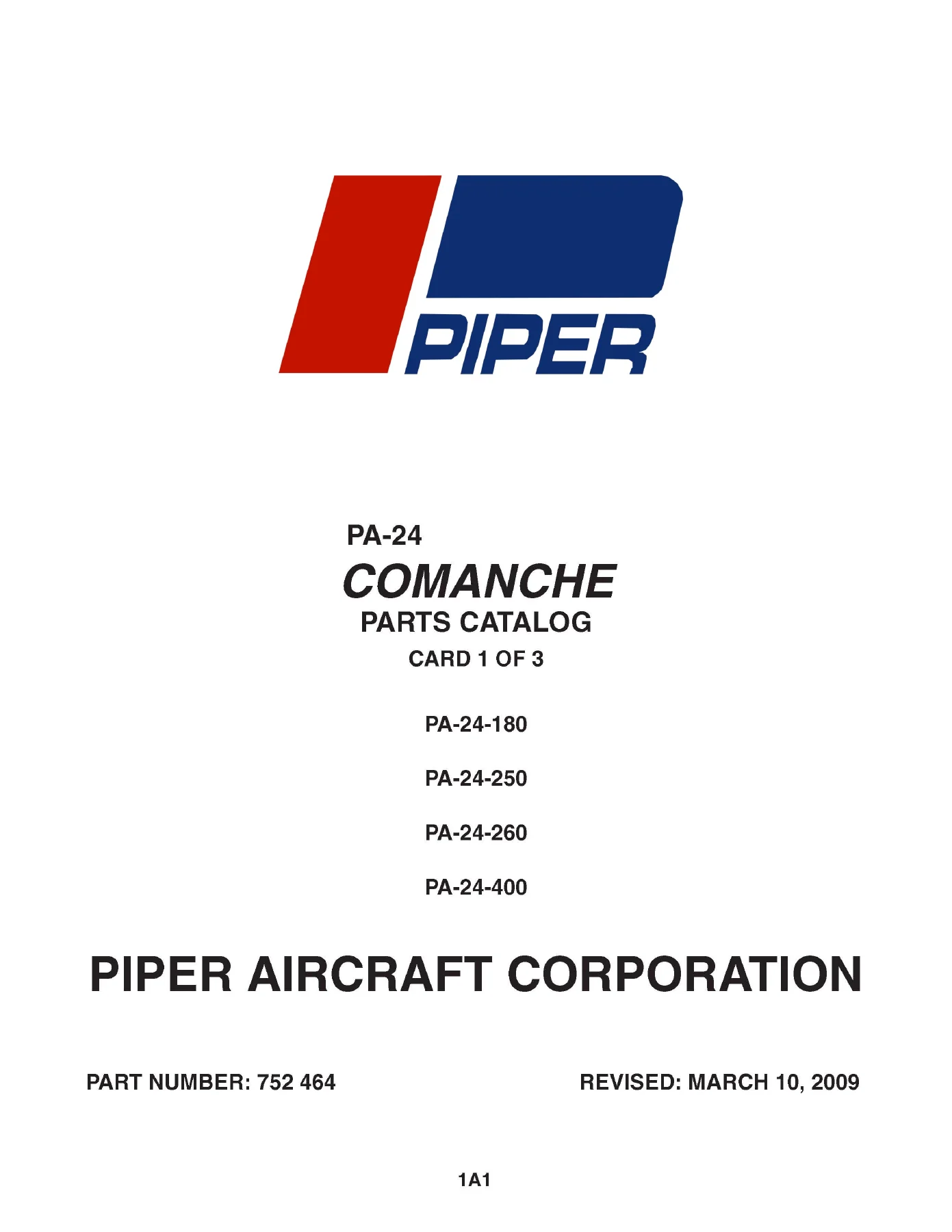
Piper PA-24 Comanche 180/250/260/400 Factory Parts Catalog 2009 Manual PDF — PDF page 1 preview
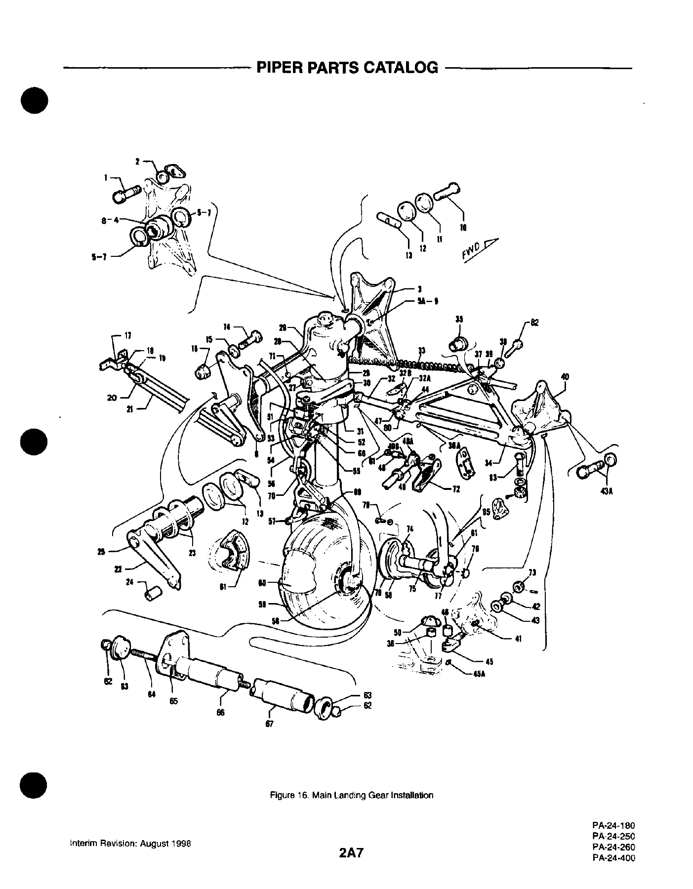
Piper PA-24 Comanche 180/250/260/400 Factory Parts Catalog 2009 Manual PDF — PDF page 255 preview
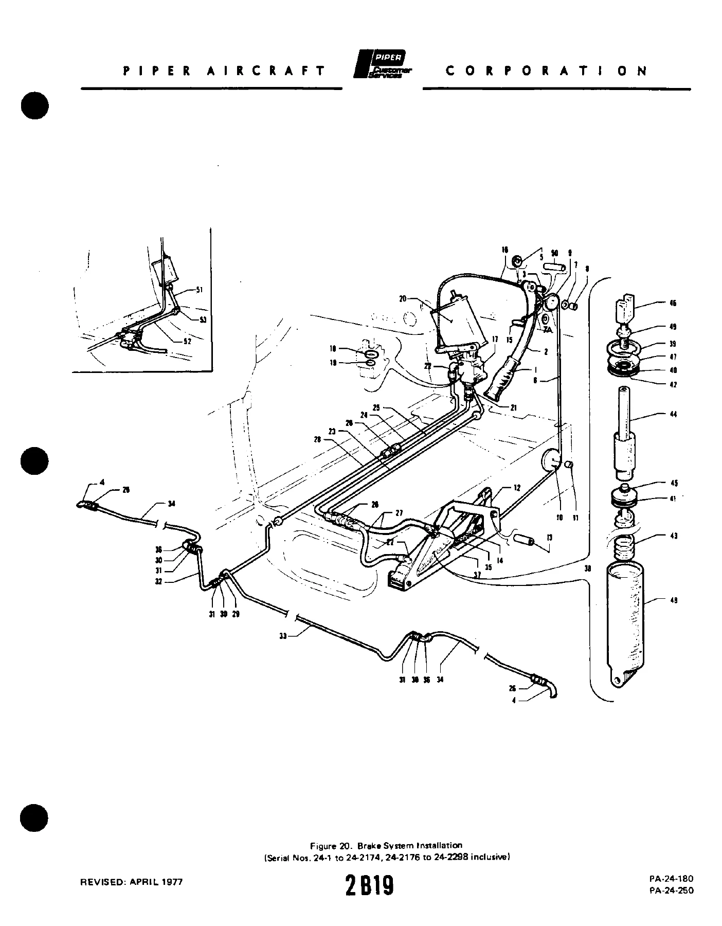
Piper PA-24 Comanche 180/250/260/400 Factory Parts Catalog 2009 Manual PDF — PDF page 291 preview

What This Manual Enables You To Do

With this Piper PA-24 Comanche Parts Catalog, you can:

  • Identify every part on your aircraft with confidence using factory drawings and part numbers.
  • Order replacement parts accurately from Piper distributors or dealers.
  • Understand the relationship between assemblies and their constituent sub-components.
  • Verify the correct part for your specific serial number.
  • Plan and budget for maintenance, restoration, or upgrade projects.
  • Locate parts for optional equipment, repair kits, and special tools.

Having the correct parts catalog is essential for any owner, mechanic, or restorer working on a Piper Comanche. Using the wrong part can lead to costly delays and improper fit. This PA-24 Comanche Parts Catalog PDF removes the guesswork, putting the entire Piper factory parts system at your fingertips.

Instant PDF Delivery. No shipping, no waiting. After purchase, you will receive immediate access to download this comprehensive manual to your computer, tablet, or phone. It is fully printable for use in the hangar or workshop. Secure your copy of the official Piper Parts Catalog and get your Comanche parts right, every time.
Reviews

There are no reviews yet.

Be the first to review “Piper PA-24 Comanche 180/250/260/400 Factory Parts Catalog 2009 Manual PDF”

What Our Customers Say

★★★★★ Live reviews from customers
Loading customer reviews...
0
    0
    Your Cart
    Your cart is emptyReturn to Shop
    🛒
    Recently Purchased
    🕒 verified order