
Learjet 31 Series Illustrated Parts Catalog IPB-102 PDF – Revision 25
Original price was: $39.95.$23.95Current price is: $23.95.
1775-page Learjet 31 Series illustrated parts catalog with numerical references, exploded diagrams, effectivity notes and replacement-part listings.
Description
Learjet 31 Series Illustrated Parts Catalog IPB-102 PDF – Revision 25
The Learjet 31 Series Illustrated Parts Catalog IPB-102 PDF – Revision 25 is a detailed replacement-parts reference for the standard production configuration of the Learjet 31 series aircraft. The 1775-page English PDF combines illustrated assemblies, itemized parts lists, numerical references and the explanatory material needed to interpret the catalog correctly. The original publication is dated June 8, 1993, and the included Revision 25 letter is dated June 20, 2016.
This is an illustrated parts catalog, not a workshop repair manual or a flight-performance handbook. Its purpose is to help identify parts, understand their relationship to an installation or assembly, and follow the relevant effectivity and replacement notes. The introduction expressly states that the information does not constitute authority to modify an aircraft. That clear scope makes the file useful to readers seeking the actual parts-reference material rather than a general aircraft description.
Find a component by number or by its place in the aircraft
The catalog explains two practical starting points. When the part number is already known, the numerical index supplies the chapter, section, figure and item reference. The reader then goes to the illustrated figure and the corresponding parts list. When the number is unknown, the applicable chapter contents or alphabetical index can be used to locate the subject by nomenclature before identifying the item on the drawing.
This structure connects a physical component with the terminology used in the parts list. It is especially useful when a name alone is too general, or when several similar pieces appear within an assembly. The illustration establishes location and relationships, while the associated table supplies the part entry and its notes. Neither should be treated as a substitute for the other.
Assembly relationships are part of the information
The introduction explains the degree of indenture in the nomenclature column. Installations, assemblies, subassemblies, detail parts and attaching parts occupy different levels. Reading that hierarchy helps establish whether an entry refers to a complete assembly, a component within it or the hardware used to attach it. A flat list of part numbers would lose that relationship; the catalog preserves it alongside the figure references.
Next-higher-assembly and detail references provide additional links between figures. Abbreviations such as NHA, DET, LH, RH, ASSY and INSTL are explained in the opening material. The figure identification block distinguishes illustration pages, text pages and the end of a figure, while the revision date and margin symbols identify changed material. These conventions make the large file more usable once the reader understands its format.
Effectivity and replacement notes require the correct context
Aircraft effectivity is expressed through alphabetical codes in the parts list. The introduction makes an important point: the interpretation printed below a figure applies to that figure only. A letter encountered in one assembly should not automatically be carried into another. Conditional usage notes and modification-dependent applicability also need to remain attached to the relevant entry.
The catalog directs readers to aircraft logbooks when part effectivity depends on modifications performed. It also distinguishes alternate parts, superseded parts, inactive spares and explicit replacement instructions. Notes such as alternate-for, when-exhausted-use and for-spares-use are not merely decorative text. They help explain why several numbers may appear beneath a related item and why the first visible number is not necessarily the correct selection for every aircraft.
The introduction also explains non-significant leading zeros in certain Learjet dash numbers. Its stated example treats a dash number and the corresponding form with non-significant zeros as the same part. That convention should be interpreted as described in the catalog rather than extended into a rule that arbitrary changes to a part number are acceptable. The full entry, figure and effectivity remain the proper reference.
Aircraft systems, structure and powerplant installations
The chapter organization spans aircraft general, airframe systems, structure and powerplant subjects. Placards and markings begin the aircraft-general group. Air-conditioning, autoflight, communications, electrical power, equipment and furnishings, fire protection, flight controls, fuel and hydraulic power are included in the airframe-system group, together with ice and rain protection and the indicating or recording systems.
Landing gear, lights, navigation, oxygen, pneumatic, water and waste, and electrical panels or multipurpose parts extend that system coverage. The structure chapters address doors, fuselage, nacelles and pylons, stabilizers, windows and wings. Powerplant-related chapters include powerplant installation, engine fuel and control, ignition, engine controls, engine indicating, oil and starting. These are parts-catalog subjects; their presence does not imply that overhaul instructions or performance limitations are supplied.
Detailed illustrated examples within the catalog
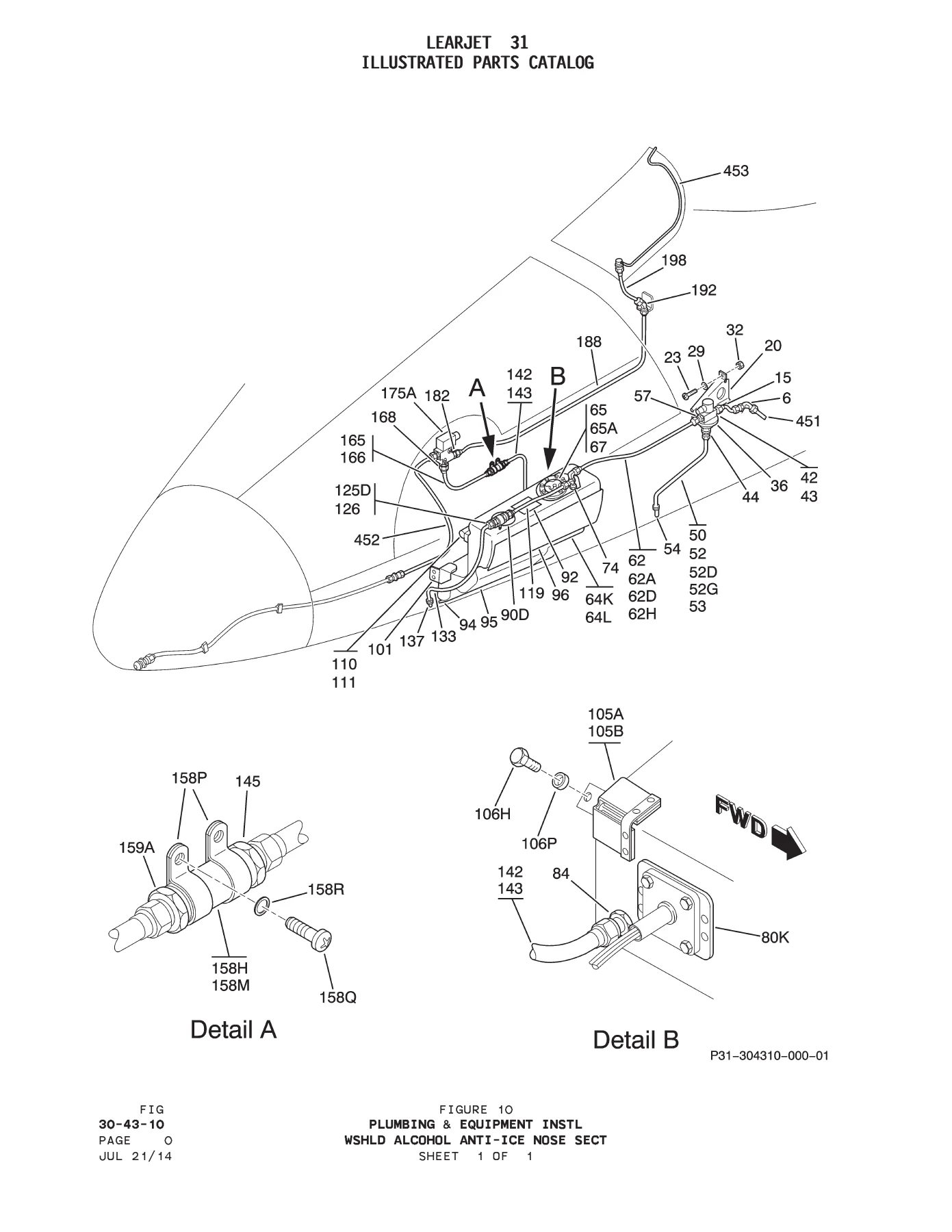
The windshield alcohol anti-ice installation provides an example of the parts detail available. Its illustrated nose-section arrangement is paired with lists covering the alcohol pressure tank, pressure-regulating and shutoff equipment, filters, tubing, supports, float switch, relief valve and associated hardware. The list preserves alternate and replacement notes alongside the named components. This allows the drawing to be used for orientation while the table supplies the exact entry that needs further applicability checking.
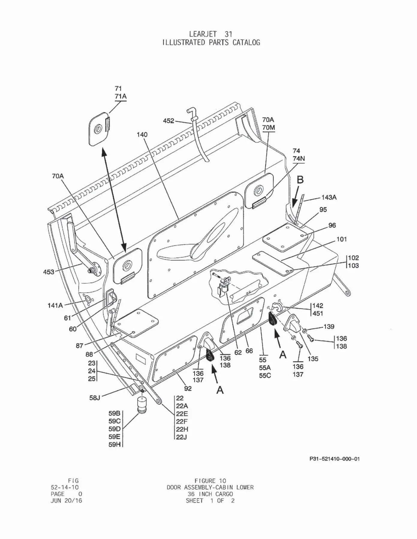
The lower cabin door material includes the 36-inch cargo-door assembly. Exploded illustrations and associated lists identify structural pieces, latch arms, seals, switches, access covers, springs, hinges and attaching hardware. Different door-latch positions and successive part entries remain distinguishable in the nomenclature. This is useful for understanding an assembly as a collection of related components without assuming that every illustrated option applies to every aircraft.
Landing-gear indication and control entries identify such equipment as the gear-control panel, control switch, gear-unsafe/down indication, horn-mute equipment, relays and circuit-board assemblies. The starting material identifies left- and right-engine cranking-system equipment, start indications, ignition/start circuit breakers, cross-start relay equipment and related electrical references. These examples demonstrate the combination of mechanical and electrical parts information in the file.
Use the catalog as a reference, with the full entry intact
A productive lookup starts with the component or installation, continues through its figure, and finishes with the parts-list entry and the associated effectivity interpretation. If the list points to a next-higher assembly or a separate detail figure, that reference completes the relationship. If it specifies a replacement or alternate, preserve the wording and the aircraft applicability rather than selecting by visual resemblance alone.
The catalog includes references to other publications where appropriate. For example, the starting-system material points electrical connector questions to Chapter 20 of the wiring manual. Such a reference defines the boundary of the present catalog; it does not mean the complete wiring manual is included in this PDF. Keeping these boundaries clear helps readers choose the correct companion reference when a question extends beyond illustrated parts identification.
Keep illustrations and list pages paired
A figure can extend over several pages, beginning with one or more illustrated sheets and continuing with parts-list text and effectivity interpretations. The catalog explains how its page identification blocks mark that sequence. Checking the end of the figure helps ensure that a lookup includes the notes associated with the list, rather than stopping at the first page containing a familiar component name.
IMAGES PREVIEW
The two-sheet lower cabin-door illustration is a useful example of this organization. The drawing provides the spatial relationship, while later pages distinguish latch positions, seal pieces, switches and access equipment. Looking at both parts of the reference preserves the detail that makes an illustrated catalog more useful than a standalone exploded picture.
File Details
- Aircraft: Learjet 31 Series, standard production configuration as described in the introduction.
- Manual: Illustrated Parts Catalog, IPB-102.
- Original publication date: June 8, 1993.
- Included revision letter: Revision 25, June 20, 2016.
- Language and format: English PDF, 1775 pages.
- Reference content: illustrated assemblies, parts lists, indices, effectivity and replacement notes.
Chapters Covered
- 11 – Placards and Markings.
- 21 – Air Conditioning; 22 – Auto Flight; 23 – Communications.
- 24 – Electrical Power; 25 – Equipment and Furnishings.
- 26 – Fire Protection; 27 – Flight Controls.
- 28 – Fuel; 29 – Hydraulic Power.
- 30 – Ice and Rain Protection; 31 – Indicating and Recording Systems.
- 32 – Landing Gear; 33 – Lights; 34 – Navigation.
- 35 – Oxygen; 36 – Pneumatic; 38 – Water and Waste.
- 39 – Electrical Panels and Multipurpose Parts.
- 52 – Doors; 53 – Fuselage; 54 – Nacelles and Pylons.
- 55 – Stabilizers; 56 – Windows; 57 – Wings.
- 71 – Powerplant; 73 – Engine Fuel and Control.
- 74 – Ignition; 76 – Engine Controls; 77 – Engine Indicating.
- 79 – Oil; 80 – Starting.
A substantial Learjet parts reference for repeated consultation
This catalog is useful for preparing a parts inquiry, identifying assembly relationships and understanding the source’s effectivity and supersession conventions. The original page images preserve the drawings, columns and notes that give each entry its meaning. Because much of the document is scanned, visual consultation remains useful where a text search does not locate a term or where a small character needs confirmation.
Keep the aircraft configuration, figure reference and complete part entry together when recording a lookup. That creates a more useful reference than copying an isolated number, particularly where similar assemblies have different effectivity or replacement history. The catalog’s systematic chapter and figure organization supports returning to the same information for later comparison.
Instant PDF delivery after payment provides access without shipping time. Open the Learjet 31 Series parts reference in a compatible PDF reader and print selected diagrams or parts-list pages for reference. The file offers detailed identification material while retaining its proper role as a parts catalog and its stated boundary against authorizing aircraft modification.
Reviews
There are no reviews yet.