★ TRUSTED BY 321,897+ PROFESSIONALS WORLDWIDE
🏒
Trusted Business
Verified & Licensed
πŸ›‘οΈ
Virus Free Files
100% Safe Downloads
πŸ”’
Secure Payment
SSL Protected
⚑
Instant Delivery
Available Immediately
Sale!

Piper PA-31-350 Chieftain 1973-1984 Illustrated Airplane Parts Catalog – 1994 Revision

Original price was: $39.95.Current price is: $24.95.

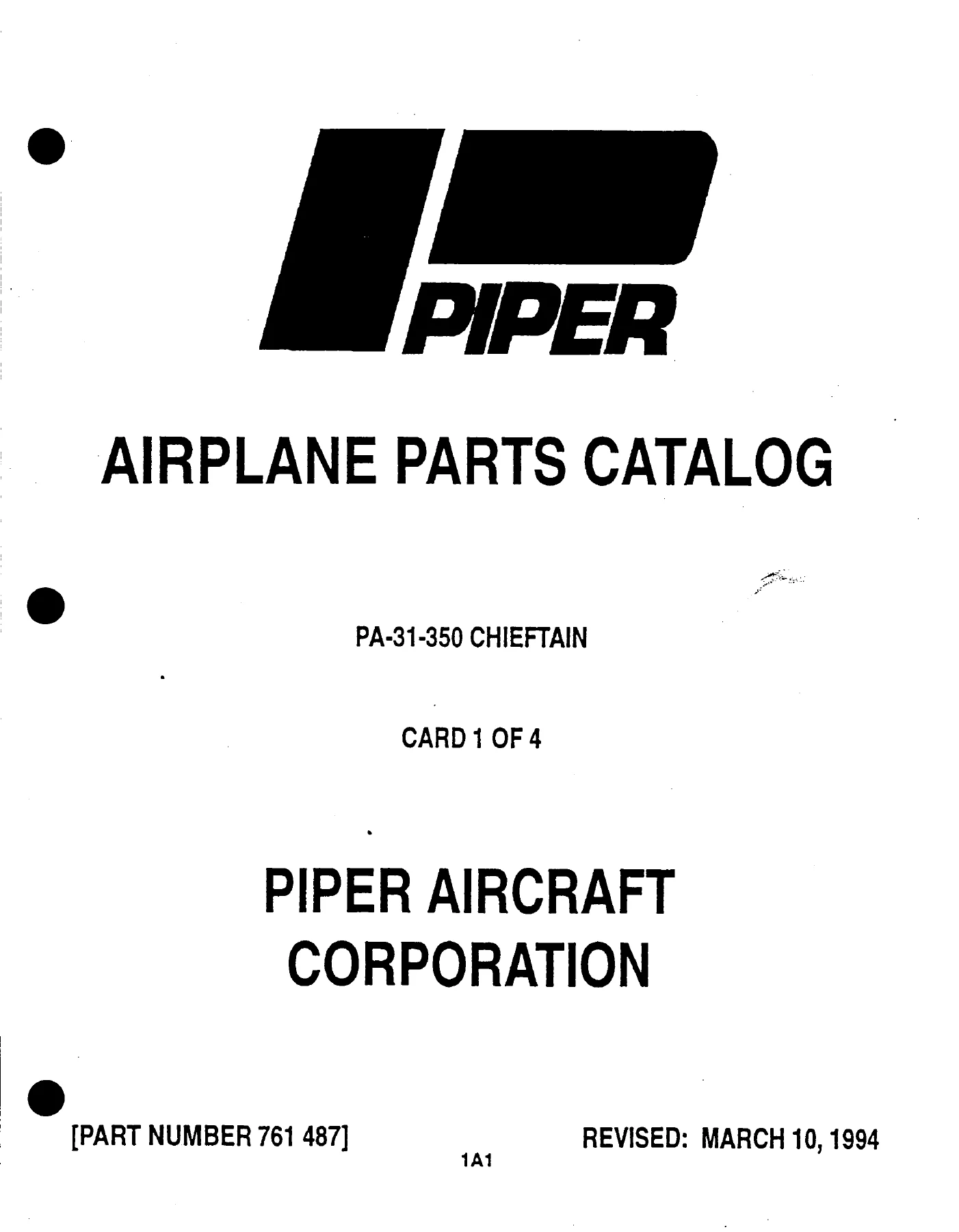
Illustrated 885-page Piper PA-31-350 Chieftain airplane parts catalog covering 1973-1984 serial-number groups, major airframe and aircraft systems, optional equipment and repair kits. Part No. 761 487, revised March 10, 1994.

⚑
Instant PDF Download
Available immediately
πŸ’Ύ
Save to Your Device
Download & keep forever
πŸ›‘οΈ
Antivirus Scanned
100% virus-free
🌍
Trusted Worldwide
175,000+ customers

Description

Piper PA-31-350 Chieftain 1973-1984 Illustrated Airplane Parts Catalog – 1994 Revision

This illustrated parts catalog is a detailed identification reference for the PA-31-350 Chieftain. It was prepared to provide positive identification of replacement parts through numbered illustrations, figure-and-index references, part numbers, nomenclature, quantities required and aircraft serial-number effectivity. The catalog covers PA-31-350 aircraft identified in its serial-number information from the 1973 through 1984 model years and carries Piper Aircraft Corporation part number 761 487 with a revision date of March 10, 1994.

Across 885 PDF pages, the catalog follows the aircraft from major wing and fuselage structure through tail surfaces, landing gear, cabin equipment, instruments, power plant, fuel, flight controls, hydraulics, environmental equipment, electrical systems and electronics. It also includes placards and exterior stencils, optional equipment kits, repair kits, special-tool references and a numerical index. The many exploded and assembly illustrations make the PA-31-350 Chieftain parts catalog especially useful when the task is to identify an assembly, trace the relationship between a parent assembly and its component parts, or confirm which listed part applies to a particular aircraft serial number.

File Details

  • Manual type: Illustrated Airplane Parts Catalog
  • Brand / model: Piper PA-31-350 Chieftain
  • Coverage shown: 1973-1984 PA-31-350 aircraft serial-number groups
  • Language: English
  • Page count: 885 pages
  • File format: PDF
  • Part number: 761 487
  • Revision: March 10, 1994

How the Catalog Identifies Parts

The catalog is organized around illustrations and matching parts lists. A figure number identifies the illustration, while the index number points to the individual item shown in that figure. The corresponding parts-list columns provide the part number, code where applicable, nomenclature, quantity required and serial numbers affected. Indentation in the nomenclature column is used to show assembly relationships, helping distinguish a complete assembly from the items contained within it.

Serial-number effectivity is a major part of this reference. The PA-31-350 serial-number information identifies separate production ranges for the 1973 through 1984 model years, and many individual figure listings further divide applicability when parts changed during production or when specific equipment or modification kits were installed. For parts identification, this makes the aircraft model and serial number important companions to the figure and part number.

The catalog itself gives a clear limitation: it is intended for replacement-part identification and states that it must not be used for rigging and installation purposes. Use the Piper PA-31-350 Chieftain 1973-1984 Illustrated Airplane Parts Catalog – 1994 Revision as a parts and effectivity reference rather than as a substitute for procedures required for rigging or installation work.

Complete PDF Bookmark Tree

Complete Bookmarks

The complete bookmarks in the β€œPiper PA-31-350 Chieftain 1973-1984 Illustrated Airplane Parts Catalog – 1994 Revision” are as follows:

761-487 – CHIEFTAIN PARTS CATALOG – PA-31-350p. 1
AEROFICHE EXPLANATION AND REVISION STATUSp. 2
INTRODUCTIONp. 3
TABLE OF CONTENTSp. 9
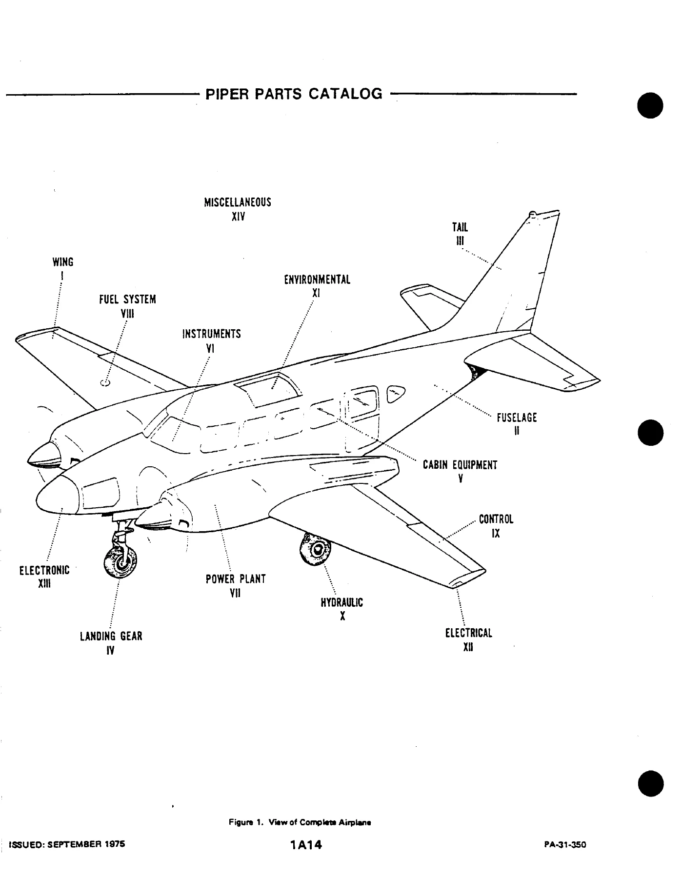
FIGURE 1. VIEW OF COMPLETE AIRPLANEp. 14
SECTION I – WING GROUPp. 15
FIGURE 2. WING INSTALLATIONp. 15
FIGURE 3. WING PANEL INBOARD PARTS INSTALLATIONp. 21
FIGURE 4 WING PANEL OUTBOARD PARTS INSTALLATIONp. 25
FIGURE 5 WING PANEL LEADING EDGE ASSEMBLYp. 29
FIGURE 6. LEADING EDGE SPAR ASSEMBLYp. 33
FIGURE 7 WING PANEL REAR SPAR ASSEMBLYp. 37
FIGURE 8. AILERON ASSEMBLYp. 45
FIGURE 9. FLAP ASSEMBLYp. 49
SECTION II – FUSELAGE GROUPp. 54
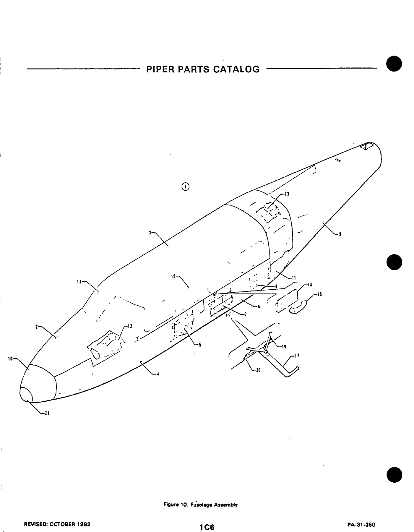
FIGURE 10. FUSELAGE ASSEMBLYp. 54
FIGURE 11. FUSELAGE UPPER FORWARD SECTIONp. 57
FIGURE 12. FUSELAGE UPPER CABIN SECTION ASSEMBLYp. 61
FIGURE 13. PILOT DOOR FUSELAGE FRAME INSTALLATIONp. 65
FIGURE 14. FUSELAGE LOWER FORWARD SECTION ASSEMBLYp. 68
FIGURE 15. FUSELAGE LOWER FORWARD FRAME ASSEMBLYp. 73
FIGURE 16. LOWER REAR SECTION ASSEMBLYp. 79
FIGURE 17. FUSELAGE LOWER CENTER FRAME ASSEMBLYp. 84
FIGURE 18. FUSELAGE LOWER REAR FRAME ASSEMBLYp. 87
FIGURE 19. CARGO DOOR FUSELAGE FRAME INSTALLATIONp. 90
FIGURE 20. FUSELAGE AFT SECTIONp. 95
FIGURE 21. FLOORBOARD INSTALLATIONp. 101
FIGURE 22. STRUCTURE INSTALLATION, STA. 57 TO STA 215p. 104
FIGURE 23. STRUCTURE INSTALLATION, STA. 215 TO STA. 244p. 107
FIGURE 24. WINDSHIELD INSTALLATIONp. 111
FIGURE 25. WINDOW INSTALLATION (SERIAL NOS. 31-5001 TO 31-7552177 INCL.)p. 115
FIGURE 25A. WINDOW INSTALLATION (SERIAL NOS. 31-7752001 AND UP)p. 119
FIGURE 26. EMERGENCY EXIT WINDOW INSTALLATIONp. 123
FIGURE 27. CABIN ENTRANCE DOOR INSTALLATIONp. 128
FIGURE 28. UPPER CABIN ENTRANCE DOORp. 132
FIGURE 29. LOWER CABIN ENTRANCE DOORp. 135
FIGURE 30. FORWARD BAGGAGE DOOR INSTALLATIONp. 141
FIGURE 31. CARGO DOOR ASSEMBLY AND INSTALLATIONp. 145
FIGURE 32. PILOT DOOR INSTALLATIONp. 149
FIGURE 33. PILOT DOOR ASSEMBLY (COMPLETE)p. 152
SECTION III – TAIL SURFACES GROUPp. 157
FIGURE 34. TAIL SURFACES INSTALLATIONp. 157
FIGURE 35. FIN ASSEMBLYp. 161
FIGURE 36. RUDDER ASSEMBLYp. 165
FIGURE 37. STABILIZER ASSEMBLYp. 169
FIGURE 38. ELEVATOR ASSEMBLYp. 173
SECTION IV – LANDING GEAR GROUPp. 178
FIGURE 39. MAIN LANDING GEAR INSTALLATIONp. 178
FIGURE 40. MAIN GEAR SRUT ASSEMBLYp. 184
FIGURE 41. MAIN WHEEL ASSEMBLY (CLEVELAND)p. 189
FIGURE 41A. MAIN WHEEL ASSEMBLY (GOODYEAR)p. 192
FIGURE 42. MAIN WHEEL BRAKE ASSEMBLY (CLEVELAND) (SERIAL NOS. 31-5001 TO 31-7652075 INCL.)p. 195
FIGURE 42A. MAIN WHEEL BRAKE ASSEMBLY (CLEVELAND) (SERIAL NOS. 31-7652076 AND UP)p. 198
FIGURE 42B. MAIN WHEEL BRAKE ASSEMBLY (CLEVELAND) (SERIAL NOS. 31-7852121, 31-8052031 AND UP)p. 201
FIGURE 42C MAIN WHEEL BRAKE ASSEMBLY (GOODYEAR)p. 204
FIGURE 43. NOSE LANDING GEAR INSTALLATIONp. 207
FIGURE 44. NOSE GEAR STRUT ASSEMBLYp. 213
FIGURE 45 NOSE WHEEL ASSEMBLYp. 218
FIGURE 46. NOSE GEAR STEERING MECHANISM INSTALLATIONp. 221
FIGURE 47 BRAKE SYSTEM INSTALLATIONp. 224
FIGURE 48. DUAL BRAKE INSTALLATIONp. 228
FIGURE 49. MASTER CYLINDER AND PARKING BRAKE VALVEp. 231
SECTION V – CABIN EQUIPMENT GROUPp. 239
FIGURE 50. FURNISHINGS INSTALLATION – CARGO VERSIONp. 239
FIGURE 51. FURNISHING INSTALLATION – COMMUTER VERSION (S/N 31-5001 TO 31-7652177 INCL)p. 243
FIGURE 51A. FURNISHING INSTALLATION-COMMUTER VERSION (S/N 31-7752001 AND UP)p. 246
FIGURE 52. FURNISHINGS INSTALLATION – CORPORATE VERSION (S/N 31-5001 TO 31-7652177 INCL.)p. 252
FIGURE 53. FURNISHINGS INSTALLATION – EXECUTIVE VERSION (S/N 31-6001 TO 31-7652177 INCL)p. 255
FIGURE 53A. FUMISHING INSTALLATION – EXECUTIVE VERSION (S/N 31-7752001 AND UP)p. 259
FIGURE 54. CABIN INTERIOR FINISHING INSTALLATION (S/N 31-5001 TO 31-7652177 INCL.)p. 267
FIGURE 54A. CABIN INTERIOR FINISHING INSTALLATION (S/N 31-7752001 TO 31-7852029 INCL)p. 272
FIGURE 54B. CABIN INTERIOR FINISHING INSTALLATION (S/N 31-7852030 AND UP)p. 276
FIGURE 55. CABIN HEADLINER INSTALLATIONp. 282
FIGURE 56. CARPET INSTALLATIONp. 285
FIGURE 57. BAGGAGE COMPARTMENTS FINISHING INSTALLATIONp. 289
FIGURE 58. SEAT INSTALLATION – FRONTp. 293
FIGURE 59. SEATS INSTALLATION – THIRD AND FOURTH FORWARD FACINGp. 300
FIGURE 59A. SEATS INSTALLATION – THIRD AND FOURTH FORWARD FACING (S/N 31-8152001 AND UP)p. 306
FIGURE 60. SEATS INSTALLATION – THIRD AND FOURTH AFT FACINGp. 310
FIGURE 60A. SEATS INSTALLATION – THIRD AND FOURTH AFT FACING (S/N 31-8152001 AND UP)p. 315
FIGURE 61. SEATS INSTALLATION PASSENGERp. 319
FIGURE 62. SEAT INSTALLATION – NINTHp. 327
FIGURE 63. SEAT INSTALLATION – TENTHp. 332
FIGURE 63A. SEATS INSTALLATION – TENTH (S/NS 31-8152001 AND UP)p. 336
FIGURE 64. CABIN DIVIDER PANELS INSTALLATION (S/N 31-4001 TO 31-7652177 IND.)p. 340
FIGURE 84A. CABIN PRIVACY CURTAIN INSTALLATIONp. 343
FIGURE 65. REFRESHMENT CABINET AND BEVERAGE DISPENSER INSTALLATION (S/N 31-5001 TO 31-7652177 INCL.)p. 346
FIGURE 66. REFRESHMENT CABINET AND BEVERAGE DISPENSER INSTALLATION (S/N 31-5001 TO 31-7652177 INCL.)p. 350
FIGURE 67. TOILET INSTALLATION – SIDE FACINGp. 353
FIGURE 68. TOILET INSTALLATION – 9TH SEAT POSITIONp. 357
FIGURE 68A TOILET INSTALLATION – 9TH SEAT POSITION (S/N 31-772096 AND UP)p. 361
TOILET INSTALLATION – 10TH SEAT POSITION (S/N 31-5001 TO 31-7652177 INCL)p. 365
SECTION VI – INSTRUMENTS GROUPp. 368
FIGURE 70. INSTRUMENT PANEL INSTALLATIONp. 368
FIGURE 71. DUAL INSTRUMENT PANEL INSTALLATIONp. 374
FIGURE 72. MISCELLANEOUS AIR AND FLUID LINES INSTALLATIONp. 378
FIGURE 73. DUAL INSTRUMENT AIR SYSTEM INSTALLATIONp. 382
FIGURE 74. INSTRUMENT PRESSURE SYSTEM INSTALLATION (S/N 31-5001 TO 31-7652123 INCL.)p. 385
FIGURE 74A. INSTRUMENT PRESSURE SYSTEM INSTALLATION (S/N 31-7652124 AND UPp. 389
FIGURE 75. STATIC PRESSURE SYSTEM INSTALLATIONp. 393
FIGURE 76. TACHOMETER SHAFT INSTALLATIONp. 397
SECTION VII – POWER PLANT GROUPp. 400
FIGURE 77. POWER PLANT INSTALLATIONp. 400
FIGURE 78. ENGINE BAFFLE INSTALLATIONp. 405
FIGURE 79. OIL COOLER AND BREATHER SYSTEM INTALLATIONp. 408
FIGURE 80. THREE BLADE PROPELLER ASSEMBLYp. 412
FIGURE 81. PROPELLER SYNCHROPHASER SYSTEM INSTALLTION (S/N 31-5001 TO 31-7852037 INCL.)p. 416
FIGURE 81A. PROPELLER SYNCHROPHASER SYSTEM INSTALLATION (S/N 31-7852038 AND UP)p. 419
FIGURE 82. ENGINE CONTROLS INSTALLATIONp. 422
FIGURE 83. ENGINE COWL INSTALLATIONp. 426
FIGURE 84. COWL FLAP ACTUSING MECHANISM INSTALLATIONp. 429
FIGURE 85. NACELLE INSTALLATIONp. 433
FIGURE 86. NACELLE LOCKER DOOR ASSEMBLY AND INSTALLATIONp. 438
SECTION VIII – FUEL SYSTEM GROUPp. 443
FIGURE 87. LEFT ENGINE FUEL SYSTEM INSTALLATIONp. 443
FIGURE 88 RIGHT ENGINE FUEL SYSTEM INSTALLATIONp. 448
FIGURE 89. FUEL FLOW AND PRESSURE GAUGE INSTALLATIONp. 453
FIGURE 90. FUEL SYSTEM COMPONENTSp. 457
FIGURE 91. FUEL CONTROLS INSTALLATIONp. 460
FIGURE 92. MAIN FUEL CELL AND LINER INSTALLATIONp. 465
FIGURE 93. AUXILIARY FUEL CELL AND LINER INSTALLATIONp. 469
FIGURE 93A. NACELLE FUEL SYSTEM INSTALLAION (NAYAK) (S/N 314152001 AND UP)p. 473
SECTION IX – CONTROL SYSTEM GROUPp. 483
FIGURE 94 PEDESTAL INSTALLATIONp. 483
FIGURE 95. PEDESTAL CONTROL ASSEMBLYp. 488
FIGURE 96. AILERON CONTROL INSTALLATIONp. 492
FIGURE 97. AILERON TRIM INSTALLATIONp. 496
FIGURE 98. RUDDER CONTROL INSTALLATIONp. 501
FIGURE 99. RUDDER TRIM INSTALLAIONp. 505
FIGURE 100. ELEVATOR CONTROL INSTALLATIONp. 509
FIGURE 101. ELEVATOR TRIM INSTALLATIONp. 513
FIGURE 102. FLAP CONTROL INSTALLATIONp. 517
FIGURE 103. CONTROL WHEEL INSTALLATIONp. 522
FIGURE 104. RUDDER PEDAL INSTALLATIONp. 527
SECTION X – HYDRAULIC SYSTEM GROUPp. 531
FIGURE 105. FORWARD HYDRAULIC SYSTEM INSTALLATIONp. 531
FIGURE 106. AFT HYDRAULIC SYSTEM INSTALLATIONp. 535
FIGURE 107. HYDRAULIC PUMPS INSTALLATIONp. 538
FIGURE 108. HYDRAULIC SYSTEM COMPONENTS (OZONE)p. 542
FIGURE 108A HYDRAULIC SYSTEM COMPONETS (WIEBEL)p. 546
FIGURE 109. HYDRAULIC POWERPAK ASSEMBLY (OZONE)p. 550
FIGURE 109A. HYDRAULIC POWERPAK COMPONENTS (OZONE)p. 554
FIGURE 110. HYDRAULIC POWERPAK ASSEMBLY (WIEBEL)p. 557
FIGURE 110A. HYDRAULIC POWERPAK COMPONENTS (WIEBEL)p. 561
FIGURE 111. LANDING GEAR SELECTOR MECHANISM INSTALLATIONp. 564
SECTION XI – ENVIRONMENTAL GROUPp. 568
FIGURE 112. HEATER AND DEFROSTER SYSTEM INSTALLATIONp. 568
FIGURE 112A. HEATER AND DEFROSTER SYSTEM INSTALLATIONp. 572
FIGURE 113. HEATER INSTALLATIONp. 576
FIGURE 113A. HEATER INSTALLATIONp. 579
FIGURE 114. HEATER ASSEMBLYp. 582
FIGURE 115. HEATER COMPONENTSp. 586
FIGURE 116. VENTILATION SYSTEM INSTALLATIONp. 590
FIGURE 116A. AIR DISTRIBUTION DUCT INSTALLATION (S/N 31-7852030 AND UP)p. 594
FIGURE 117. CABIN EXHAUST VENT AND BLOWER INSTALLATIONp. 597
FIGURE 118. AIR CONDITIONING EVAPORATOR INSTALLATIONp. 600
FIGURE 119. AIR CONDITIONING FREON SYSTEM INSTALLATIONp. 603
FIGURE 120. AIR CONDITIONING CONDENSER AND SCOOP INSTALLATIONp. 606
FIGURE 121. OXYGEN SYSTEM INSTALLATION (FORWARD MOUNTED BOTTLE) (S/N 31-5001 TO 31-7652177 INCL)p. 609
FIGURE 121A. OXYGEN SYSTEM INSTALLATION (FORWARD MOUNTED BOTTLE) (S/N 31-7752001 AND UP)p. 614
FIGURE 122. OXYGEN SYSTEM INSTALLATION (AFT MOUNTED BOTTLE) (S/N 31-5001 TO 31-7652177 INCL.)p. 618
FIGURE 122A. OXYGEN SYSTEM INSTALLATION (AFT MOUNTED BOTTLE) (S/N 31-7752001 AND UP)p. 622
FIGURE 123. FORWARD PNEUMATIC DE-ICING SYSTEM INSTALLATION (S/N31-5001 TO 31-7652123 INCLp. 626
FIGURE 123A FORWARD PNEUMATIC DE-ICING SYSTEM INSTALLATION (S/N 31-7652124 TO 31-7952250 INCL.)p. 630
FIGURE 123B. FORWARD PNEUMATIC DE-ICING SYSTEM INSTALLATION (S/N 31-8052001 AND UP)p. 634
FIGURE 124. AFT PNEUMATIC DEICING SYSTEM INSTALLATION (S/N 31-5001 TO 31-7652123 INCLp. 638
FIGURE 124A. AFT PNEUMATIC DE-ICING SYSTEM INSTALLATION (S/N 31-7652124 AND UP)p. 641
SECTION XII – ELECTRICAL SYSTEM GROUPp. 644
FIGURE 125. FORWARD ELECTRICAL SYSTEM INSTALLATIONp. 644
FIGURE 126. AFT ELECTRICAL SYSTEM INSTALLATIONp. 649
FIGURE 127. FUSELAGE HARNESS INSTALLATIONp. 652
FIGURE 128. PRIMARY AND AUXILIARY ELECTRICAL POWER INSTALLATIONp. 656
FIGURE 129. SWITCH AND CIRCUIT BREAKER SYSTEM INSTALLATIONp. 661
FIGURE 130. OVERHEAD SWITCH PANEL ASSEMBLYp. 665
FIGURE 131. LANDING LIGHT INSTALLATIONp. 669
FIGURE 132. PROPELLER ELECTRIC DE-ICER INSTALLATIONp. 672
FIGURE 133. ELECTRIC WINDSHIELD WIPER INSTALLATIONp. 675
FIGURE 134. STROBE LIGHTS INSTALLATION (S/N 31-5001 TO 31-7305052 INCL)p. 678
FIGURE 134A. STROBE LIGHTS INSTALLATION (S/N 31-7305053 AND UP)p. 681
SECTION XIII – ELECTRONICS GROUPp. 689
FIGURE 135. BENDIX RADAR INSTALLATION (ROR-110)p. 689
FIGURE 135A. BENDIX RADAR INSTALLATION (RDR-130)p. 692
FIGURE 135B. BENDIX RADAR INSTALLATION (RDR-140)p. 695
FIGURE 135C. BENDIX RADAR INSTALLATION (RDR.150)p. 698
FIGURE 135D. BENDIX RADAR INSTALLATION (RDR-16O)p. 701
FIGURE 135E. BENDIX RADAR INSTALLATION (RDR-230 HP)p. 704
FIGURE 136. RCA RADAR INSTALLATIONp. 709
FIGURE 136A. KING RADAR INSTALLATION (KWX-40/KWX-50)p. 712
FIGURE 136B. KING RADAR INSTALLATION IKWX-56)p. 715
FIGURE 136C. RCA RADAR INSTALLATION (PRIMUS 200)p. 718
FIGURE 137. RADAR ALTIMETER INSTALLATION (BONZER)p. 721
FIGURE 137A. RADAR ALTIMETER INSTALLATION (KING) (S/N 31-7852001 AND UP)p. 724
FIGURE 138. ALTIMATIC PILOT III B-1INSTALLATIONp. 727
FIGURE 138A. ALTIMATIC PILOT III C INSTALLATION (S/N 31-7552054 TO 31-8152203 INCL)p. 732
FIGURE 139. GLIDE SLOPE COUPLER INSTALLATIONp. 736
FIGURE 140. ALTIMATIC V F/ D-1 AUTOPILOT INSTALLATION (S/N 31-5001 TO 31-7752099 INCL)p. 739
FIGURE 141. ALTIMATIC V-1 AUTOPILOT INSTALLATION (S/N 31-5001 TO 31-7752099 INCL))p. 744
FIGURE 142. FLIGHT DIRECTOR/AUTOPILOT INSTALLATION (BENDIX FCS-810) (S/N 31-7752100 TO 31-8052221 INCL.)p. 749
FIGURE 143. AUTOPILOT INSTALLATION (BENDIX FCS-810) (S/N 31-7752100 TO 31-8052221 INCL.)p. 754
FIGURE 144. ALTIMATIC X F/O AUTOPILOT INSTALLATION (S/N 31-7852001 TO 31-8152203 INCL)p. 758
FIGURE 145. ALTIMATIC X AUTOPILOT INSTALLATION (S/N 31-7852001 TO 31-8152203 INCL)p. 762
FIGURE 145A. KING AUTOPILOT (KAP-200) AND KING AUTOPILOT F/D (KFC-200) INSTALLATIONSp. 766
FIGURE 145B. BENDIX FCS-870 AUTOPILOT AND F/D AUTOPILOT INSTALLATION (S/N 31-8152001 AND UP)p. 770
FIGURE 145C. CENTURY 41 AUTOPILOT AND F/D AUTOPILOT INSTALLATION (S/N 31-8252001 AND UP)p. 774
FIGURE 146. RMI SYSTEM INSTALLATION (RADIO MAGNETIC INDICATOR)p. 778
FIGURE 147 ANTENNA CABLE, SPEAKER, STATIC WICKS, RAMP HAILER AND MIKE INSTALLATIONp. 781
FIGURE 148. RADIO COOLING INSTALLATIONp. 785
FIGURE 149 PIPER PM-1 MARKER BEACON INSTALLATIONp. 788
FIGURE 150. RADIO JUNCTION BOXESp. 791
FIGURE 151. PIPER AUTOMATIC LOCATOR (ELT) INSTALLATION (GARRETT MFG. LTD.)p. 794
FIGURE 152. PIPER AUTOMATIC LOCATOR (ELT) INSTALLATION (COMMUNICATIONS COMPONENTS CORP.)p. 797
FIGURE 1 52A. PIPER AUTOMATIC LOCATOR (ELT) INSTALLATION (NARCO AVIONICS)p. 801
FIGURE 152B. KING RADIO TELEPHONE INSTALLATIONp. 804
RADIO INSTALLATION DRAWINGSp. 807
SECTION XIV – MISCELLANEOUS GROUPp. 812
FIGURE 1 53. PLACARDS AND EXTERIOR STENCILSp. 812
OPTIONAL EQUIPMENT KITS AND REPAIR KITp. 820
NUMERICAL INDEXp. 824

Chapters Covered

  • Section I – Wing Group
    • Wing installation and wing panel inboard/outboard parts
    • Wing panel leading edge and leading edge spar assemblies
    • Wing panel rear spar assembly
    • Aileron assembly
    • Flap assembly
  • Section II – Fuselage Group
    • Fuselage assembly and upper forward/cabin sections
    • Pilot-door and cargo-door fuselage frame installations
    • Lower forward, lower rear and center frame assemblies
    • Fuselage aft section and floorboard installation
    • Structure installations, windshield and window installations
    • Emergency exit, cabin entrance, baggage, cargo and pilot doors
  • Section III – Tail Surfaces Group
    • Tail surfaces installation
    • Fin assembly
    • Rudder assembly
    • Stabilizer assembly
    • Elevator assembly
  • Section IV – Landing Gear Group
    • Main landing gear installation and main gear strut assembly
    • Main wheel assemblies and brake assemblies
    • Nose landing gear, nose gear strut and nose wheel assemblies
    • Nose gear steering mechanism
    • Brake system, dual brake installation, master cylinder and parking brake valve
  • Section V – Cabin Equipment Group
    • Cargo, commuter, executive commuter and executive furnishings installations
    • Cabin interior finishing, headliner and carpet installations
    • Baggage compartment finishing
    • Front and passenger seat installations, including additional seating positions
    • Cabin divider panels and privacy curtain installations
    • Refreshment cabinet, beverage dispenser and toilet installations
  • Section VI – Instruments Group
    • Instrument panel and dual instrument panel installations
    • Miscellaneous air and fluid lines
    • Dual instrument air and instrument pressure systems
    • Static pressure system
    • Tachometer shaft installation
  • Section VII – Power Plant Group
    • Power plant and engine baffle installations
    • Oil cooler and breather system
    • Three-blade propeller assembly
    • Propeller synchrophaser system
    • Engine controls, engine cowl and cowl flap actuating mechanism
    • Nacelle and nacelle locker door assembly/installations
  • Section VIII – Fuel System Group
    • Left and right engine fuel systems
    • Fuel flow and pressure gauge installation
    • Fuel system components and fuel controls
    • Main and auxiliary fuel cell and liner installations
    • Nacelle fuel system installation where applicable
  • Section IX – Control System Group
    • Pedestal installation and pedestal control assembly
    • Aileron control and aileron trim installations
    • Rudder control and rudder trim installations
    • Elevator control and elevator trim installations
    • Flap control, control wheel and rudder pedal installations
  • Section X – Hydraulic System Group
    • Forward and aft hydraulic system installations
    • Hydraulic pumps and hydraulic system components
    • Hydraulic powerpak assemblies and components
    • Landing gear selector mechanism installation
  • Section XI – Environmental Group
    • Heater and defroster system and heater installations
    • Ventilation, air distribution, cabin exhaust vent and blower installations
    • Air-conditioning evaporator, Freon system, condenser and scoop installations
    • Forward- and aft-mounted oxygen system installations
    • Forward and aft pneumatic deicing system installations
  • Section XII – Electrical System Group
    • Forward and aft electrical system installations
    • Fuselage harness installation
    • Primary and auxiliary electrical power installation
    • Switch and circuit breaker system and overhead switch panel assembly
    • Landing lights, propeller electrical deicer, windshield wiper and strobe-light installations
  • Section XIII – Electronics Group
    • Bendix, RCA and King radar installations and radar altimeter installations
    • AltiMatic, Bendix, King and Century autopilot / flight-director installations listed by the catalog
    • RMI system, glide-slope coupler and antenna/cable installations
    • Radio cooling, marker beacon, radio junction boxes and radio installation drawings
    • Automatic locator transmitter installations and King radio telephone installation
  • Section XIV – Miscellaneous Group
    • Placards and exterior stencils
    • Optional equipment kits and repair kits
    • Special-tool references
    • Numerical index

Taken as a whole, the catalog provides a system-by-system map of the PA-31-350 and connects each illustrated assembly to its corresponding parts information. Structural assemblies such as wings, spars, fuselage frames, control surfaces and doors are shown alongside mechanical and equipment groups including landing gear, brakes, engine-related installations, fuel, controls and hydraulics. Cabin, environmental, electrical and avionics/electronics sections extend the reference into interior fittings, heating and ventilation, oxygen and deicing equipment, wiring-related installations, radar, autopilot and ELT installations.

IMAGES PREVIEW

Piper PA-31-350 Chieftain 1973-1984 Illustrated Airplane Parts Catalog - 1994 Revision β€” PDF page 1 preview
Piper PA-31-350 Chieftain 1973-1984 Illustrated Airplane Parts Catalog - 1994 Revision β€” PDF page 14 preview
Piper PA-31-350 Chieftain 1973-1984 Illustrated Airplane Parts Catalog - 1994 Revision β€” PDF page 54 preview

Serial-Number Effectivity and Configuration Detail

The serial-number tables and figure-specific effectivity notes are important when working with this catalog because the same general assembly may have different listed parts depending on production range or installed equipment. The catalog identifies the 1973 PA-31-350 Navajo Chieftain group beginning with serial numbers 31-5001, 31-5002, 31-5003 and 31-7305005 through 31-7305125, then provides separate ranges for each model year through the 1984 PA-31-350 Chieftain range 31-8452001 through 31-8452021. Throughout the parts listings, additional effectivity breaks appear for changes such as wheel and brake configurations, doors, cabin arrangements, fuel-system equipment, environmental equipment and electronics installations.

Many figure pages also include code explanations that direct the reader to related figures or identify conditions such as a particular modification kit, service letter, optional installation or serial-number break. This helps a technician or parts researcher move from a visual assembly to the applicable component listing without treating every configuration as identical.

Illustrated Assembly Reference

The 1994-revision Piper PA-31-350 Chieftain parts catalog contains extensive pictorial coverage rather than relying on part-number lists alone. The complete-airplane view maps the major catalog groups to their locations on the aircraft, while subsequent figures break assemblies into indexed components. Examples include wing installation, wing panel structure, leading-edge spars, rear spars, ailerons, flaps, fuselage sections, door frames and floorboards, followed later by landing gear, cabin, instrument, power-plant, fuel, control, hydraulic, environmental, electrical and electronic installations.

For maintenance planning and parts research, these illustrations are useful for recognizing where a component belongs and for finding the index number that leads to its nomenclature and part number. The catalog also preserves configuration-specific notes and references to replacement or modification kits, which can be essential when identifying parts on aircraft that have changed equipment during service.

Identify the Correct PA-31-350 Parts Reference

The Piper PA-31-350 Chieftain 1973-1984 Illustrated Airplane Parts Catalog – 1994 Revision supports detailed replacement-part identification, assembly research, serial-number effectivity checks and comparison of illustrated component relationships across the aircraft. It is useful when preparing for maintenance, identifying a part seen in an assembly, checking the listed quantity or nomenclature, or determining which catalog entry applies to a specific PA-31-350 serial number. Because the catalog explicitly separates parts by figures, codes and effectivity, it helps reduce the risk of relying on a visually similar component that belongs to a different production range or equipment configuration.

Correct part identification matters before repair or replacement work begins, especially on an aircraft catalog that documents years of configuration changes and optional installations. This PDF gives you the complete 885-page reference in one digital file for convenient viewing on compatible devices and printing of the pages you need. Delivery is instant after payment, with no physical book and no shipping delay. Use it as the illustrated parts and effectivity reference it is intended to be, while following the appropriate maintenance data for rigging and installation procedures.
Reviews

There are no reviews yet.

Be the first to review “Piper PA-31-350 Chieftain 1973-1984 Illustrated Airplane Parts Catalog – 1994 Revision”

What Our Customers Say

β˜…β˜…β˜…β˜…β˜… Live reviews from customers
Loading customer reviews...
0
    0
    Your Cart
    Your cart is emptyReturn to Shop
    πŸ›’
    Recently Purchased
    πŸ•’ verified order