★ TRUSTED BY 321,897+ PROFESSIONALS WORLDWIDE
🏢
Trusted Business
Verified & Licensed
🛡️
Virus Free Files
100% Safe Downloads
🔒
Secure Payment
SSL Protected
Instant Delivery
Available Immediately
Sale!

Cessna 182 and Skylane 1962-1973 Illustrated Parts Catalog P515-12

Original price was: $32.95.Current price is: $18.95.

Cessna Aircraft Company illustrated parts catalog P515-12 for Model 182, 182 Skylane, and A182 airplanes, 1962 thru 1973, with usable-on serial codes and Temporary Revision 1.

Instant PDF Download
Available immediately
💾
Save to Your Device
Download & keep forever
🛡️
Antivirus Scanned
100% virus-free
🌍
Trusted Worldwide
175,000+ customers

Description

Cessna 182 and Skylane 1962-1973 Illustrated Parts Catalog P515-12

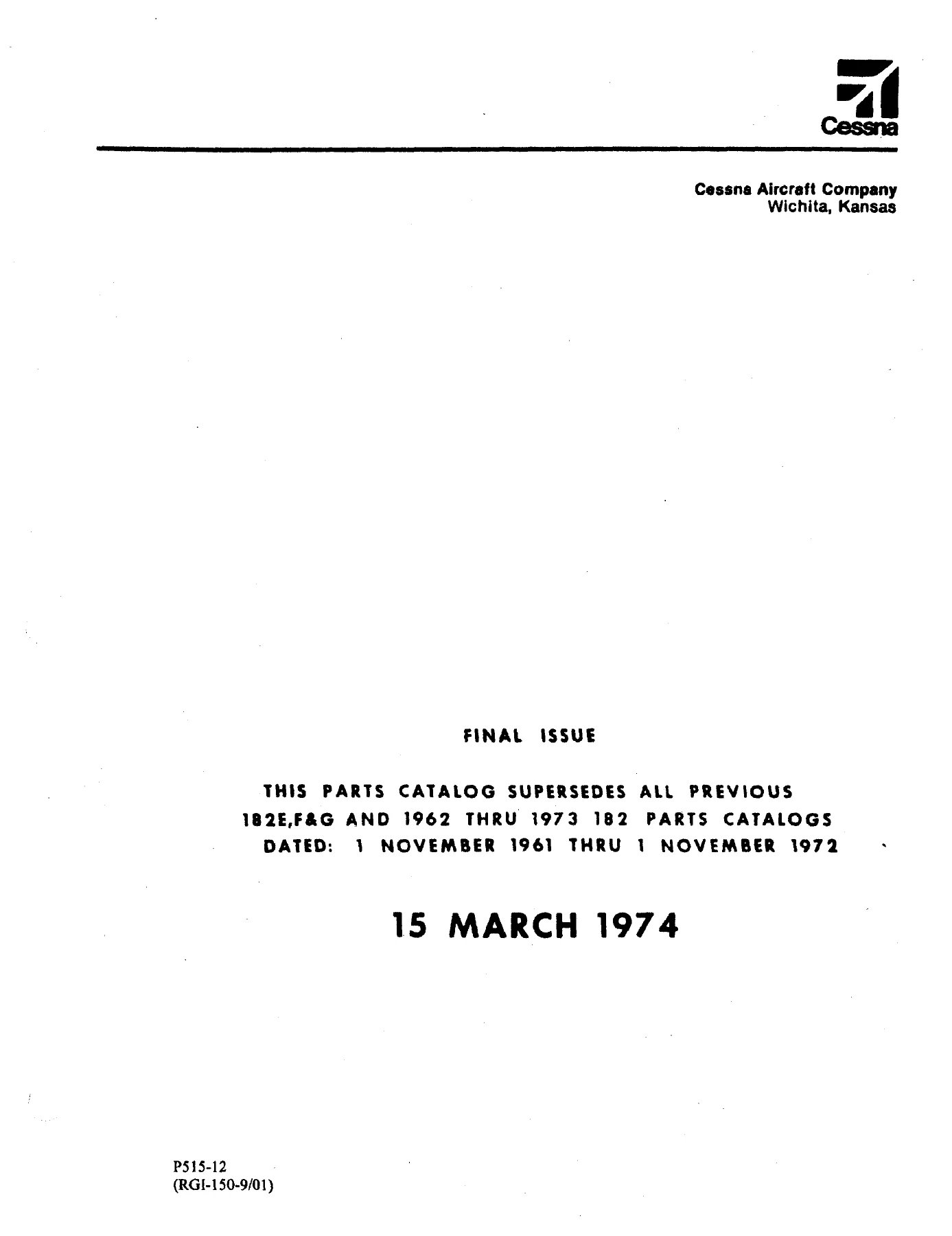
The Cessna 182 and Skylane 1962-1973 Illustrated Parts Catalog P515-12 is the Cessna Aircraft Company group-assembly parts list for Model 182, 182 Skylane, and A182 airplanes built from 1962 thru 1973. Issued as a final-issue catalog on 15 March 1974 in Wichita, Kansas, it supersedes earlier 182E, F, and G catalogs and the 1962 thru 1973 182 parts catalogs dated 1 November 1961 thru 1 November 1972. This file also includes Temporary Revision Number 1 dated 3 April 1995 plus later parts-catalog revision sheets used to keep part numbers, usable-on codes, and serialization notes current.

Use this catalog when a wing skin, cabin door, main-gear spring, cowl panel, instrument, or bulk seal must be identified by Cessna part number, quantity per assembly, and serial applicability. Each illustrated figure is keyed to an indented parts list so left-hand and right-hand details, attaching hardware, and “when exhausted use” replacements stay tied to the correct airplane block.

File Details

  • Manual type: Illustrated parts catalog
  • Brand / models: Cessna Model 182, 182 Skylane, and A182
  • Coverage years: 1962 thru 1973
  • Document number: P515-12 (paper); aerofiche P515-12AF
  • Temporary revision: P515TR1-12 dated 3 April 1995
  • Publication date: 15 March 1974 (final issue)
  • Language: English
  • Page count: 670 (PDF file)
  • File format: PDF

Airplanes and Serial Coverage

The Cessna 182 and Skylane 1962-1973 Illustrated Parts Catalog P515-12 covers the 182 / Skylane family and the A182 series listed throughout the usable-on code blocks. Serial examples printed in the catalog and revision notes include 18253599 thru 18262465 on many 182 figures, with A182 serials such as A182-0001 thru A182-0146 and A182-0147 and on called out where the later A182 configuration differs. Individual figures add finer letter codes (A, B, C, and so on) so a part used only on 18260826 thru 18261425 is not ordered for an earlier tailcone or cabin section.

Revision sheets also distinguish engine-related instrument and sending-unit parts used with the 0-470-R engine from those used with the 0-470-S engine. Order by the exact part number and usable-on letter printed against your serial; do not assume a later dash number fits an earlier airplane.

Complete PDF Bookmark Tree

Complete Bookmarks

The complete bookmarks in the “Cessna 182 and Skylane 1962-1973 Illustrated Parts Catalog P515-12” are as follows:

Parts Catalog (P515)p. 1
Letter of Transmittal (Highlights of Changes)p. 2
Temporary Revision No. 1p. 2
Parts Catalog Revision No. 75-27p. 15
Parts Catalog Revision No. 77-13p. 16
Parts Catalog Revision No. 78-9p. 17
List of Effective Pagesp. 21
Introductionp. 23
Upholstery & Interior Trimp. 38
Alphabetical Indexp. 51
Parts Listingp. 69
Figure 1. Miscellaneous Bulk Itemsp. 70
Figure 2. Placards, Nameplates & Exterior Markingsp. 74
Figure 2A. Placards, Nameplates & Exterior Markingsp. 82
Figure 3. Wing Assembly Completep. 90
Figure 4. Wing Structure Assemblyp. 95
Figure 4A. Wing Structure Assemblyp. 98
Figure 4B. Wing Structure Assemblyp. 101
Figure 5. Wing Leading Edge Assemblyp. 104
Figure 5A. Wing Leading Edge Assemblyp. 107
Figure 5B. Wing Leading Edge Assemblyp. 110
Figure 6. Wing Spar Assembliesp. 112
Figure 6A. Wing Spar Assembliesp. 115
Figure 7. Skins and Stringers Installationp. 117
Figure 7A. Skins & Stringers Installation (Fig 7A)p. 120
Figure 8. Fuel Tank Installationp. 122
Figure 8A. Fuel Tank Drain Valve Installationp. 125
Figure 9. Aileron Installationp. 126
Figure 10. Flap Installationp. 129
Figure 11. Wing Strut Installationp. 131
Figure 12. Fin & Dorsal Installationp. 133
Figure 12A. Fin & Dorsal Installationp. 135
Figure 12B. Fin & Dorsal Installationp. 137
Figure 13. Rudder Assemblyp. 139
Figure 14. Stabilizer Installationp. 142
Figure 14A. Stabilizer Installationp. 144
Figure 15. Elevator Installationp. 147
Figure 15A. Elevator Installationp. 150
Figure 16. Fuselage Assemblyp. 153
Figure 17. Fuselage Front Section Assemblyp. 155
Figure 17A. Fuselage Front Section Assemblyp. 160
Figure 18. Front Doorpost Bulkhead Assemblyp. 164
Figure 19. Console Structure Assemblyp. 167
Figure 20. Front Section Tunnel Componentsp. 169
Figure 21. Firewall Assemblyp. 171
Figure 21A. Firewall Assemblyp. 173
Figure 21B. Firewall Assemblyp. 175
Figure 22. Firewall Grommets Installationp. 177
Figure 23. Center Cabin Section Assemblyp. 179
Figure 23A. Center Cabin Section Assemblyp. 182
Figure 24. Rear Doorpost Bulkhead Assemblyp. 186
Figure 25. Lower Cabin Section Assemblyp. 189
Figure 26. Landing Gear Bulkhead Assemblyp. 194
Figure 26A. Landing Gear Bulkhead Assemblyp. 196
Figure 27. Windshield Installationp. 198
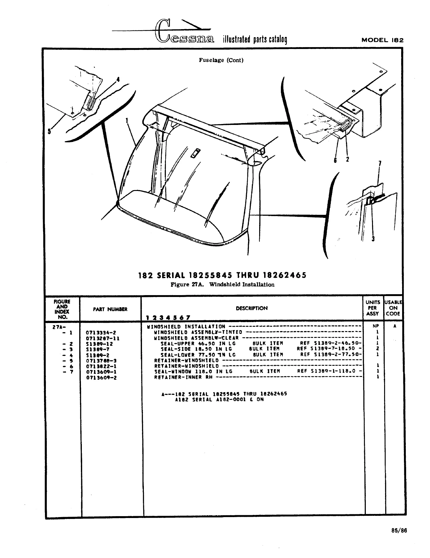
Figure 27A. Windshield Installationp. 199
Figure 28. Rear Window Installationp. 200
Figure 28A. Air Cabin Windows Installationp. 201
Figure 29. Tailcone Assembly Sta. 110.00 to 230.187p. 203
Figure 29A. Fuselage Tailcone Assemblyp. 206
Figure 29B. Tailcone Assembly – Extended Baggage Compartmentp. 208
Figure 30. Battery Box Installationp. 211
Figure 31. Aft Tailcone Assembly Sta. 209.00 to 230.187p. 213
Figure 31A. Aft Tailcone Assembly Sta. 209.00 to 230.187p. 215
Figure 32. Stringer Installationp. 217
Figure 33. Nose Gear Installationp. 219
Figure 33A. Heavy Duty Nose Gear Installationp. 221
Figure 34. Nose Gear Steering System Installationp. 223
Figure 35. Nose Gear Shock Strut Assemblyp. 225
Figure 35A. Nose Gear Shock Strut Assembly – Heavy Dutyp. 228
Figure 36. Goodyear Nose Wheel Assemblyp. 231
Figure 36A. Cleveland Nose Wheel Assemblyp. 232
Figure 36B. Nose Gear Wheel Assembly – Alternatep. 233
Figure 37. Cleveland Nose Wheel Assemblyp. 234
Figure 37A. Nose Wheel Assembly – Heavy Duty (Cleveland)p. 235
Figure 37B. Nose Wheel Assembly – Heavy Duty (Cleveland)p. 236
Figure 38. Shimmy Dampener Assemblyp. 237
Figure 38A. Shimmy Dampener Assemblyp. 238
Figure 38B. Shimmy Dampener Assemblyp. 239
Figure 39. Main Landing Gear Installationp. 240
Figure 39A. Main Landing Gear Installationp. 244
Figure 39B. Main Landing Gear Installationp. 247
Figure 40. Main Wheel & Brake Assemblyp. 250
Figure 40A. Main Wheel & Brake Assemblyp. 252
Figure 41. Left Cabin Door Assemblyp. 255
Figure 41A. Left Cabin Door Assemblyp. 259
Figure 42. Right Cabin Door Assemblyp. 262
Figure 42A. Right Cabin Door Assemblyp. 265
Figure 43. Cabin Door Latch Assemblyp. 267
Figure 43A. Cabin Door Latch Assemblyp. 269
Figure 44. Baggage Door Installationp. 271
Figure 45. Cabin Top & Firewall Upholstery Installationp. 274
Figure 45A. Cabin Top & Firewall Upholstery Installationp. 277
Figure 45B. Cabin Top & Firewall Upholstery Installationp. 280
Figure 46. Cabin Door Upholstery Installationp. 283
Figure 47. Cabin Side & Floorboard Installationp. 286
Figure 47A. Cabin Side & Floorboard Installationp. 288
Figure 47B. Cabin Side & Floorboard Installationp. 291
Figure 47C. Upholstery Cabin Side & Floorboard Installationp. 294
Figure 47D. Upholstery Cabin Side & Floorboard Installationp. 297
Figure 47E. Fuselage Soundproofing Installationp. 300
Figure 48. Front Seat Installationp. 301
Figure 49. Pilot & Co-Pilot Seat Installationp. 303
Figure 49A. Pilot & Co-Pilot Seat Installationp. 306
Figure 49B. Pilot & Co-Pilot Seat Installationp. 309
Figure 49C. Pilot & Co-Pilot Seat Installation – Standardp. 312
Figure 50. Adjustable Front Seat Installationp. 315
Figure 51. Adjustable Seat Bottom Mechanism Installationp. 317
Figure 51A. Vertically Adjustable Seat Installationp. 320
Figure 51B. Pilot & Co-Pilot Power Adjustable Seat Installp. 324
Figure 51C. Power Seat Bottom Assembly – Pilot & Co-Pilotp. 327
Figure 51D. Infinite Adjust Front Seat Installationp. 329
Figure 51E. Infinite Adjust Front Seat Installationp. 333
Figure 51F. Infinite Adjust Front Seat Installationp. 337
Figure 52. Rear Seat Installationp. 341
Figure 52A. Rear Seat Installationp. 343
Figure 52B. Rear Seat Assemblyp. 347
Figure 52C. Auxiliary Seat Installationp. 350
Figure 52D. Auxiliary Seat Installationp. 352
Figure 53. Instrument Panel Equipment Installationp. 354
Figure 53A. Instrument Panel Equipment Installationp. 358
Figure 53B. Post Lighted Instrument Panel Installationp. 362
Figure 53C. Instrument Panel Equipment Installationp. 364
Figure 53D. Post Lighted Instrument Panel Installationp. 368
Figure 53E. Instrument Panel Equipment Installationp. 370
Figure 53F. Post Lighted Instrument Panel Installationp. 375
Figure 53G. Instrument Panel Equipment Installationp. 377
Figure 53H. Post Lighted Instrument Panel Installationp. 382
Figure 53J. Instrument Panel Equipment Installationp. 384
Figure 53K. Post Lighted Instrument Panel Installationp. 389
Figure 53L. Instrument Panel Equipment Installationp. 391
Figure 53M. Post Lighted Instrument Panel Installationp. 396
Figure 53N. Post Lighted Instrument Panel Installationp. 398
Figure 53P. Post Lighted Instrument Panel Installationp. 403
Figure 53Q. Instrument Panel Installationp. 405
Figure 53R. Post Lighted Instrument Panel Installationp. 410
Figure 54. Switch Panel Installationp. 412
Figure 55. Map Compartment Installationp. 414
Figure 55A. Map Compartment Installationp. 416
Figure 56. Fuselage Equipment Installationp. 418
Figure 57. Portable Stretcher Installationp. 422
Figure 57A. Rear View Mirror & Compass Installationp. 423
Figure 57B. Rear View Mirror & Compass Installationp. 425
Figure 58. Propeller Installationp. 427
Figure 58A. Propeller Installationp. 429
Figure 59. McCauley Propeller Assemblyp. 431
Figure 59A. McCauley Propeller Assemblyp. 433
Figure 59B. McCauley Propeller Assemblyp. 436
Figure 60. Hartzell Propeller Assemblyp. 438
Figure 61. Engine Cowl Assemblyp. 440
Figure 61A. Engine Cowl Assemblyp. 443
Figure 61B. Engine Cowl Assemblyp. 446
Figure 61C. Engine Cowl Assemblyp. 449
Figure 62. Engine Installationp. 452
Figure 63. Engine Assemblyp. 455
Figure 64. Propeller Governor Assemblyp. 462
Figure 64A. Propeller Governor Assemblyp. 464
Figure 64B. Propeller Governor Assemblyp. 466
Figure 64C. Governor Assemblyp. 468
Figure 65. Exhaust Stack Assemblyp. 470
Figure 65A. Engine Exhaust Assemblyp. 472
Figure 66. Engine Baffles Installationp. 474
Figure 67. Cowl Flaps Control System Installationp. 477
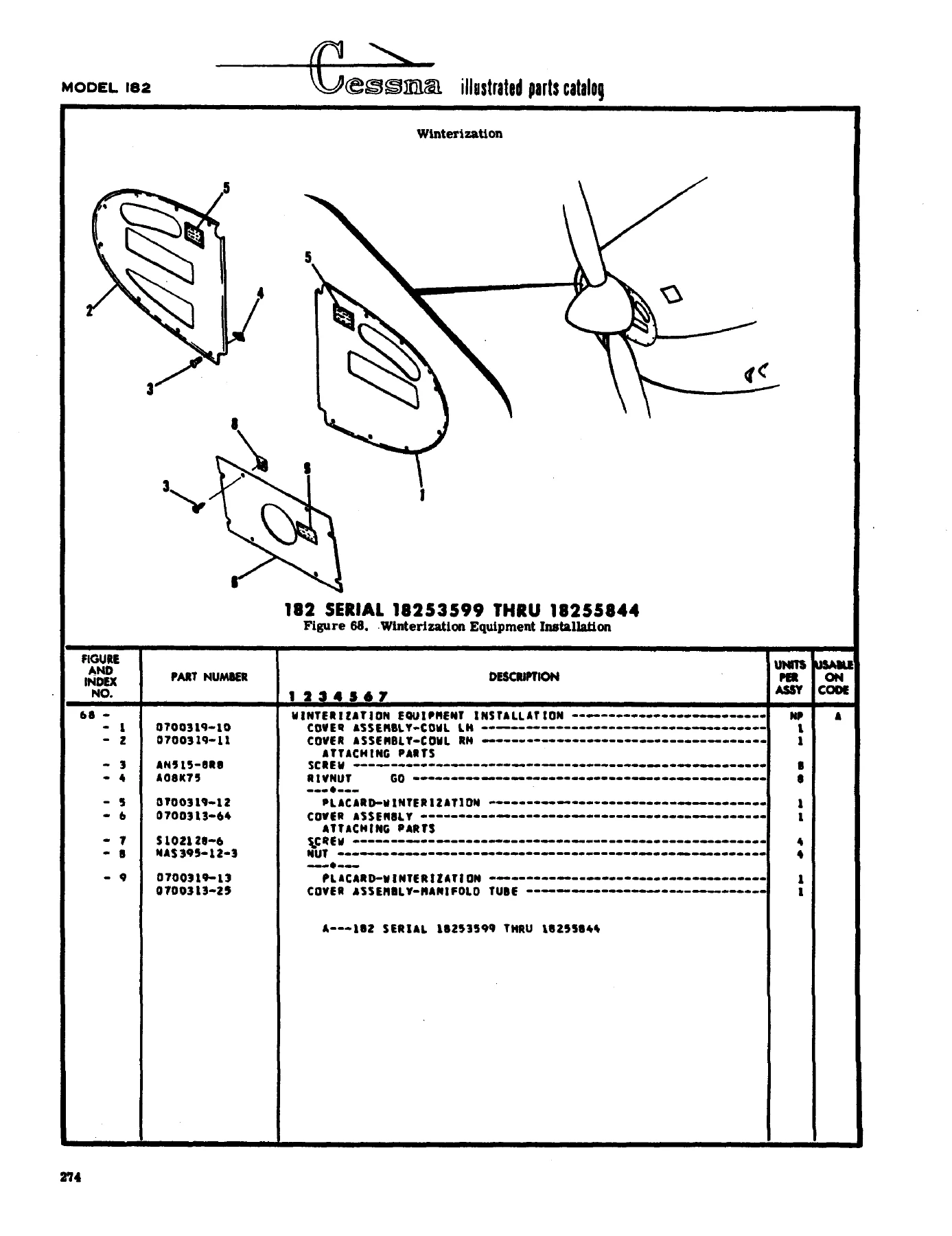
Figure 68. Winterization Equipment Installationp. 479
Figure 68A. Winterization Equipment Installationp. 480
Figure 68B. Winterization Equipment Installationp. 481
Figure 69. Cabin Ventilation Systemp. 482
Figure 69A. Cabin Ventilation Systemp. 485
Figure 70. Cabin Heating & Defrosting Systemp. 488
Figure 71. Brake System Installationp. 491
Figure 71A. Brake System Installationp. 494
Figure 72. Brake & Rudder Pedals Installationp. 498
Figure 73. Master Brake Cylinder Assemblyp. 500
Figure 74. Control Column Installationp. 501
Figure 74A. Control Column Installationp. 505
Figure 74B. Control Wheel & Switches Installationp. 509
Figure 74C. Control Wheel & Switches Installationp. 511
Figure 75. Console Installationp. 513
Figure 76. Aileron Control System Installationp. 516
Figure 76A. Aileron Controls Installationp. 519
Figure 76B. Wing Leveler Installationp. 522
Figure 77. Elevator Control Systemp. 525
Figure 78. Elevator Trim Control Systemp. 528
Figure 79. Electric Flap System Installationp. 530
Figure 79A. Flap Actuator Transmission and Motor Assemblyp. 535
Figure 79B. Flap Control Detail Installationp. 536
Figure 79C. Flap Control Detail Installationp. 539
Figure 80. Rudder Control System Installationp. 542
Figure 81. Pitot System Installationp. 544
Figure 82. Fuel System Installationp. 547
Figure 82A. Fuel System Installationp. 550
Figure 83. Fuel Strainer Assemblyp. 553
Figure 84. Fuel Strainer Drain Control Installationp. 554
Figure 84A. Fuel Strainer & Drain Control Installationp. 555
Figure 85. Fuel Primer System Installationp. 557
Figure 86. Oil System Installationp. 559
Figure 86A. Directional & Horizontal Gyro Usagep. 562
Figure 87. Vacuum System Installationp. 563
Figure 88. Vacuum System Installationp. 567
Figure 88A. Vacuum System Installationp. 569
Figure 88B. Vacuum System Installationp. 572
Figure 88C. Vacuum System Installationp. 575
Figure 89. Oxygen System Installationp. 578
Figure 89A. Oxygen System Installationp. 580
Figure 89B. Oxygen System Installationp. 583
Figure 89C. Oxygen System Installationp. 587
Figure 91. Electrical Equipment Installationp. 591
Figure 90A. Instrument Panel Lights Installationp. 596
Figure 91. Instrument Panel Lights Installationp. 598
Figure 91A. Instrument Panel Lights & Console Installationp. 600
Figure 92. Rotating Beacon Installationp. 602
Figure 92A. Flashing Beacon Light Installationp. 603
Figure 93. Courtesy Light Installationp. 606
Figure 94. Map Light Installationp. 607
Figure 95. Shock Mounted Alternator Installationp. 609
Numerical Indexp. 610

How the Catalog Is Organized

The introduction explains the two-index system: an alphabetical index at the front and a numerical index at the back that lists every part number with the figure and index where it appears. Standard Cessna “S” prefix parts, plus AN and NAS hardware, are mixed with airplane-unique 07-series and 12-series numbers. Usable-on codes sit in the far-right column and apply only to the figure on which they appear. If no code is shown against a first-column listing, that item applies to all models and serials covered by the catalog. Interchangeable later parts carry the note “when exhausted use” or the abbreviation WEU so distributors can consume old stock before switching to the later design.

Symbols used in the lists include NP (not procurable as a complete assembly), AR (as required / bulk quantity), ALT (alternate), INSTL (installation), ASSY (assembly), LH / RH, FSO (for spares order), and BKI (bulk item). Attaching parts are listed immediately under the item they fasten and are closed with a dashed separator. Quantities in the Units Per Assembly column are per figure, not per airplane, except where a note multiplies left and right installations.

Finish, trim, and interior color codes

A large front section decodes the Finish and Trim plate on the lower left door jamb. For 1962 thru 1965 airplanes the plate uses year, exterior color, upholstery scheme, and interior trim codes tied to CES-1054 paint dash numbers. From 1966 on, the plate is read as year, interior color code, optional carpet letter, and exterior trim number, with vinyl base coats called out on overall-painted airplanes. Separate how-to-order pages show how to add the second dash number on upholstered parts and on interior painted or plastic parts so a 1966 Coral interior seat skirt is not shipped in the wrong color.

Chapters Covered

  • Introduction, list of effective pages, symbols, and how-to-order notes
  • Finish and Trim plate decoding and yearly paint / upholstery code charts
  • Upholstered parts and interior painted or plastic parts ordering tables (1962–1973)
  • Alphabetical index of nomenclature to figure number
  • Figure 1 – Miscellaneous bulk items (adhesives, sealants, primers, sound deadener)
  • Decals, emblems, exterior and interior placards, winterization placards
  • Wing complete – structure, spars, skins and stringers, tips, struts, fairings
  • Aileron installation, bellcranks, cables, push-pull rods, balance weights
  • Fuel tanks, extended-range tank parts, tank vents, drain valves, selector valve
  • Flap system – electric flap installation, actuator, switch bar, position transmitter
  • Fuselage – cabin section, firewall, floorboards, tailcone, baggage door
  • Cabin doors LH/RH, door structure, latches, windows, windshield and retainers
  • Empennage – dorsal fin, stabilizer, elevator, rudder, trim tabs and cables
  • Main landing gear springs, axles, steps, brake lines, wheels and brakes
  • Nose gear, fork, shimmy damper, nose wheel (Goodyear and Cleveland callouts)
  • Seats, seat belts, shoulder harness, headrests, cabin upholstery and carpets
  • Instrument panel covers, shock panels, post-lighted panels, instrument clusters
  • Flight and engine instruments, directional and horizontal gyros, suction system
  • Engine installation, engine mount, shock mounts, baffles, oil cooler
  • Engine cowl upper and lower assemblies, access doors, nose cap, flaps
  • Exhaust stacks and muffler assemblies, carburetor air intake and heat controls
  • Propeller, spinner, governor, and related attaching parts
  • Heating and defrosting, cabin air controls, winterization cowl covers
  • Electrical – battery, alternator and shock-mounted alternator, lights, switches
  • Oxygen cylinder and regulator assemblies where listed
  • Numerical parts index mapping every part number back to figure and index

Taken together, those figures give a technician a complete illustrated breakdown of replaceable airframe, landing-gear, powerplant installation, cabin, and equipment items for the years this catalog covers. The book does not replace a service or overhaul manual; it is the parts identity and applicability document used before a purchase order is written.

IMAGES PREVIEW

Cessna 182 and Skylane 1962-1973 Illustrated Parts Catalog P515-12 — PDF page 1 preview
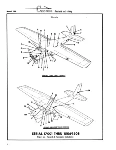
Cessna 182 and Skylane 1962-1973 Illustrated Parts Catalog P515-12 — PDF page 199 preview
Cessna 182 and Skylane 1962-1973 Illustrated Parts Catalog P515-12 — PDF page 479 preview

Using Usable-On Codes and Revision Notes

Temporary Revision 1 and the later Customer Services revision sheets change individual part numbers, swap left/right descriptions, add placards such as pitot-heat warning and fuel-fill standard versus long-range, and rewrite serialization notes at the end of many figures. Examples include changing code Z to AD on a lower cabin section assembly, inserting 0791160-19 / 0791160-22 floorboard and cabin items, correcting NAS versus AN clamp numbers, and adding 0-470-S engine lines beside existing 0-470-R instrument-cluster and cylinder-head temperature sending-unit listings.

When a figure lists both an early and a later part, read the WEU note and the serial letter before ordering. A windshield retainer, tailcone assembly, or flap actuator that is correct for 18261426 and on will not match an airplane in the 18253599 thru 18258505 block. The catalog also flags items that are no longer available and items that must be ordered with a companion kit or additional hardware (for example, converting a nose-wheel yoke to 5/16-inch bolts on airplanes prior to a stated serial).

What a Shop Can Identify from This File

A maintenance shop working a 1960s or early-1970s 182 or Skylane can pull the figure for the system being repaired, read the index numbers on the exploded view, and copy the part number, description, and units-per-assembly quantity onto the order form the introduction describes. Bulk items such as windshield seal S1389 in cut lengths, rubber mouldings, and firewall sealant are listed with the length used on one installation so the dealer can cut from stock. Corrosion-proofed parts are ordered by adding CP after the part number. Accessory kits themselves are directed to a separate Accessory Kit Catalog; they are not duplicated here.

Because the Cessna 182 and Skylane 1962-1973 Illustrated Parts Catalog P515-12 spans twelve model years plus A182, the same figure often carries several dash numbers. Matching the usable-on letter to the data plate serial is the difference between receiving a Skylane-only tinted door window and a standard 182 clear window, or between a standard main-gear axle and the heavy-duty axle used with the 8.00 x 6 wheel.

Get the Catalog and Start Identifying Parts

With this catalog on the bench you can identify wing, fuselage, landing-gear, cabin, instrument, engine-installation, fuel, control, electrical, and winterization parts for Model 182, 182 Skylane, and A182 airplanes in the 1962 thru 1973 coverage window, including the serial-coded changes captured in Temporary Revision 1. Correct part numbers and usable-on codes matter because many details changed by serial block and are not interchangeable even when the description looks similar. After payment the file is delivered as an instant PDF download—no shipping wait—so you can open it on a shop computer, tablet, or phone and print the figure you need for a work order or parts request.
Reviews

There are no reviews yet.

Be the first to review “Cessna 182 and Skylane 1962-1973 Illustrated Parts Catalog P515-12”

What Our Customers Say

★★★★★ Live reviews from customers
Loading customer reviews...
0
    0
    Your Cart
    Your cart is emptyReturn to Shop
    🛒
    Recently Purchased
    🕒 verified order