
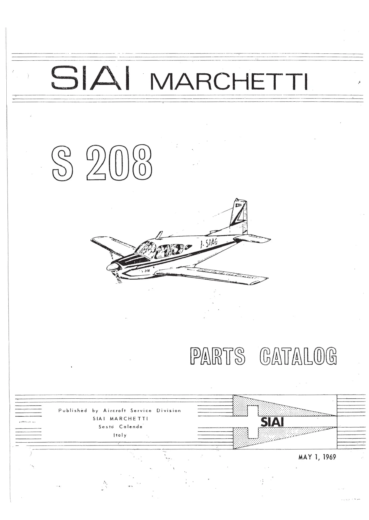
SIAI Marchetti S208 Parts Catalog May 1969 Illustrated Group Assembly List
Original price was: $29.95.$16.95Current price is: $16.95.
May 1, 1969 illustrated parts catalog for the SIAI Marchetti S208, covering 4-seat and 5-seat aircraft with exploded group-assembly lists, figure indexes, and a numerical parts index for spare-part identification.
Description
SIAI Marchetti S208 Parts Catalog May 1969 Illustrated Group Assembly List
This SIAI Marchetti S208 Parts Catalog May 1969 Illustrated Group Assembly List is the illustrated spare-parts catalog published May 1, 1969 by the Aircraft Service Division of SIAI Marchetti, Sesto Calende, Italy. It was prepared to identify and order replacement parts for the S208 airplane. The catalog is organized as an introduction, a group-assembly parts list with exploded figures, and a numerical parts list. Two complete-aircraft arrangements are listed: S 208-5 for the 5-seater and S 208-4 for the optional 4-seater.
File Details
- Manual type: Illustrated Parts Catalog (Group Assembly Parts List and Numerical Index)
- Brand / model: SIAI Marchetti S208 (S 208-5 five-seater; S 208-4 four-seater optional)
- Publisher: Aircraft Service Division, SIAI Marchetti, Sesto Calende, Italy
- Publication date: May 1, 1969
- Language: English
- Page count: 320
- File format: PDF
How This Catalog Is Organized
Section I explains figure-and-index numbering, part-number columns, indented descriptions, units-per-assembly notes (including Ref and AR), the Availability column (NP for not procurable), and the Usable On Code column used when a part applies only to certain serials. Section II is the group-assembly parts list: exploded illustrations paired with six-column lists of figure/index, part number, description, units per assembly, availability, and usable-on code. Section III is the alphanumerical numerical index that points each part number back to its figure and index. An aircraft reference-stations drawing is included so station-located items can be placed on the airframe.
The catalog tells the reader to put the complete manufacturer part number on every order and to include model designation and serial number. Attaching hardware is listed immediately under the item it attaches, with a separator line after those fasteners. Indentation shows what arrives if an assembly is ordered versus a single detail part.
IMAGES PREVIEW
Chapters Covered
- Section I – Introduction: table of contents, abbreviations, aircraft reference stations, how to use the catalog, ordering notes
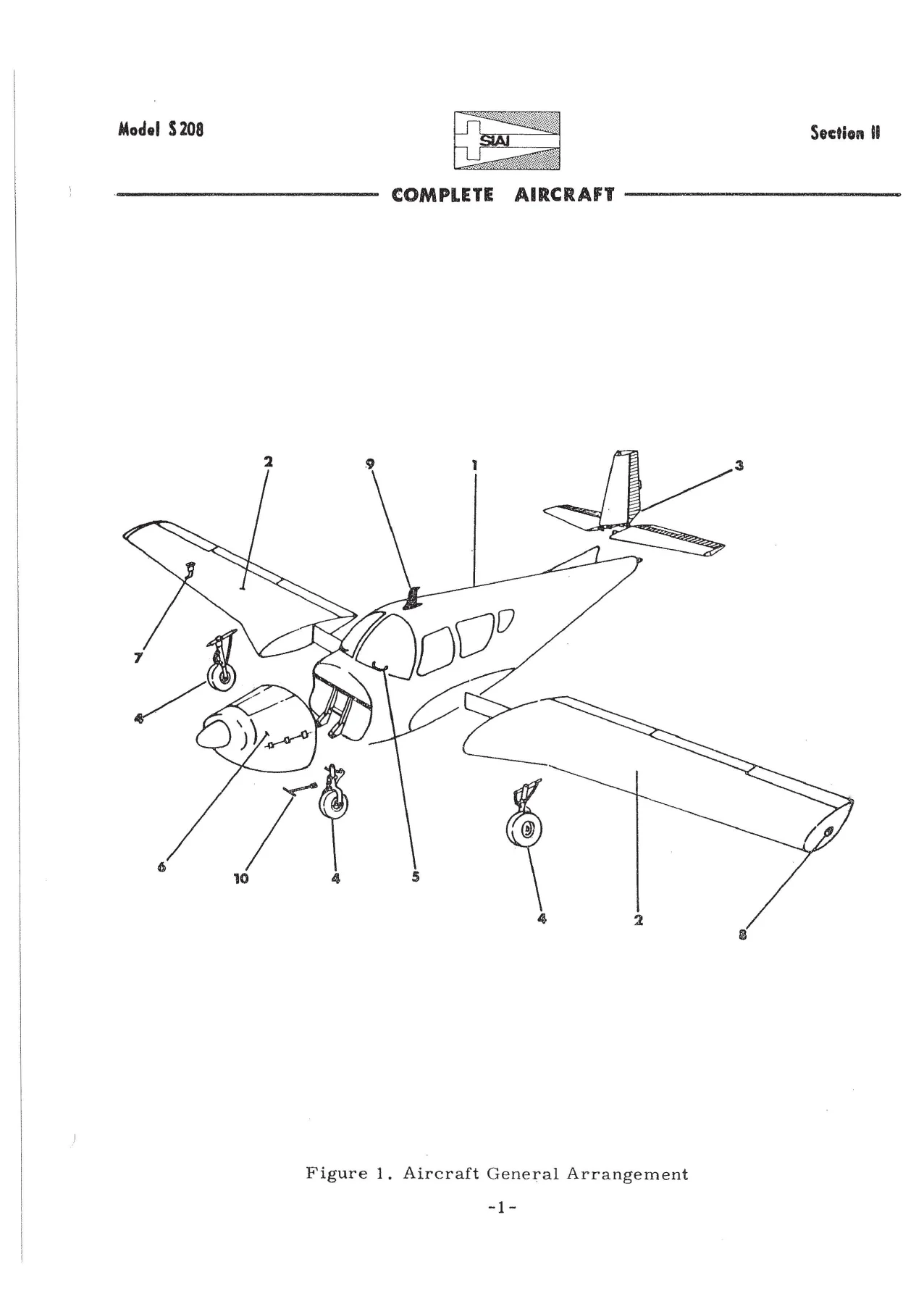
- Section II Figure 1 – General arrangement of the complete aircraft
- Group 1 Fuselage: fuselage installation; structure assemblies (forward, aft, firewall, lower structure by station); doors and window structure; forward skin; door, floorboard, and window installations; cabin door and latch; front, rear, and fifth seats; cabin furnishings; cabin vent; cabin heat and defroster; wing-to-fuselage fillets and tailcone
- Group 2 Wing: wing installation and doors; wing structure; leading edge; front and main spars; trailing-edge structure; inboard fuel tank; aileron and flap assemblies; optional wing-tip fuel tank
- Group 3 Tail: tail installation; stabilizer and fin; elevator and rudder
- Group 4 Alighting gear: general arrangement; nose landing gear installation, assembly, wheel, and steering; main landing gear installation and assembly; main wheel and brake; retract system; emergency extension drive; single and dual brake installations; brake cylinder
- Group 5 Surface controls: general arrangement; rudder and elevator controls; elevator trim-tab controls; aileron and flap controls; control column; rudder pedals; rudder trim cable; flap/rudder/elevator trim pedestal and mechanism
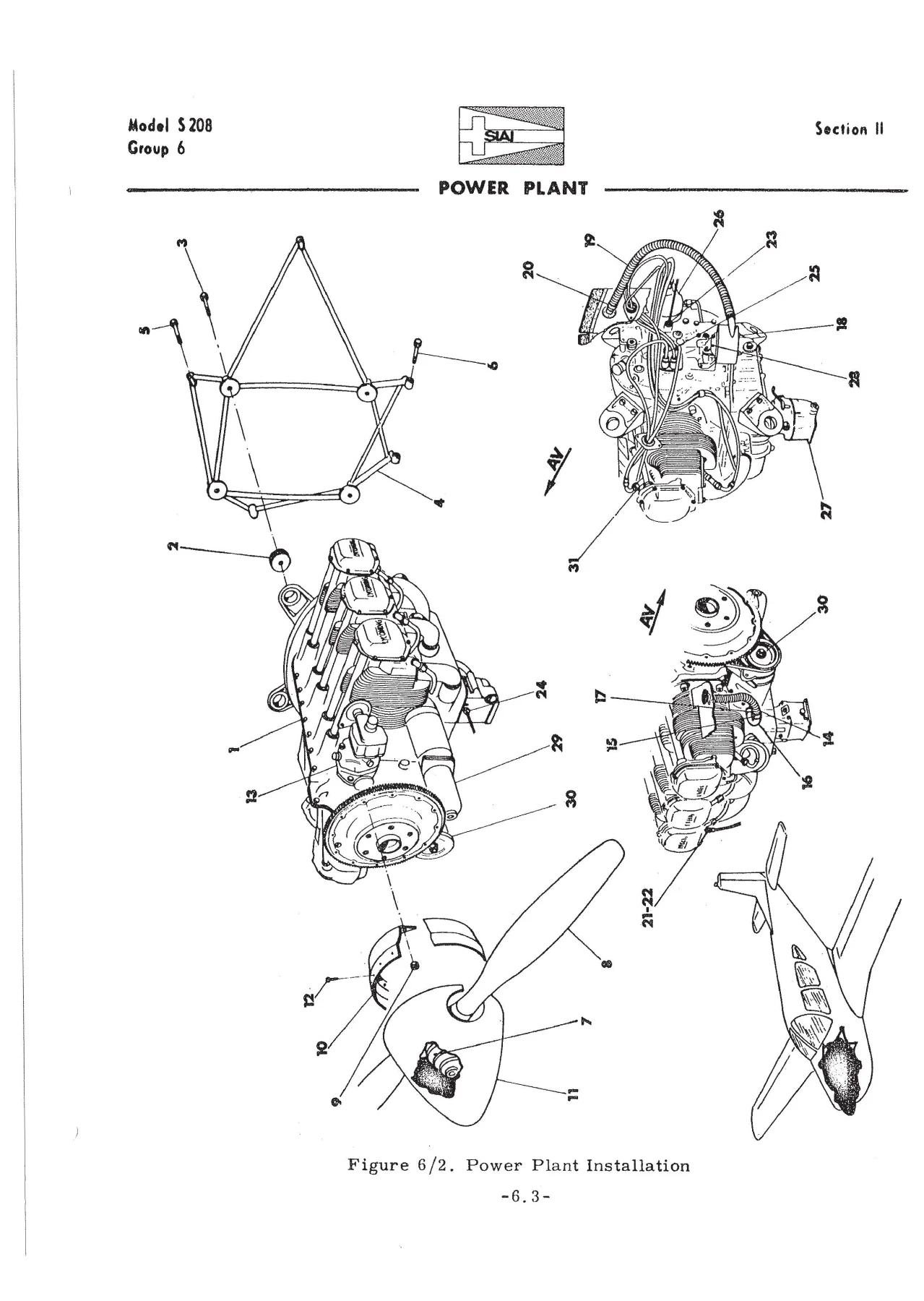
- Group 6 Power plant: general arrangement and installation; engine cowl; air box; exhaust; oil system; fuel system; fuselage fuel; engine controls; baffles; optional fuselage and wing fuel
- Group 7 Instrument system: general arrangement; panel structure and assembly; placards; pitot system; vacuum system
- Group 8 Electrical system: aircraft, wing, fuselage, engine and firewall, dome and baggage light, instrument-panel, and forward-fuselage electrical installations; battery
- Group 9 Radio system: Narco VHF/VOR, ADF and ILS installation; King VHF/VOR, ADF and ILS installation
- Group 10 Special equipment: loose tools and accessories
- Section III – Numerical Index
Taken together, those groups give a technician a station-oriented map of the S208 plus the part numbers needed to rebuild or restock each assembly. The SIAI Marchetti S208 Parts Catalog May 1969 Illustrated Group Assembly List does not replace a workshop manual; it is the illustrated identity and order document that sits beside one.
Aircraft Arrangements and Usable-On Notes
Figure 1 lists the complete airplane as S 208-5 (usable-on code A, 5 seater) and S 208-4 (usable-on code B, 4 seater optional). Matching fuselage, door, floorboard, and seat installations carry A or B codes. Other figure notes distinguish single versus dual brake installations, aircraft for Germany versus other aircraft, aircraft with an engine alternator, and aircraft with optional wing-tip fuel tanks. Where a figure uses serial breakpoints, the catalog prints those codes at the foot of the list, including serial 001 to 1-09 versus 1-10 and on, and serial 001 to 2-20 versus 2-21 and on. If no usable-on letter appears, the item applies to all serials covered by that figure.
Power Plant and Related Assemblies
Group 6 identifies the installed engine as O-540-E4A5, described as ENGINE ASSY, 260 HP (Lycoming), with Lord shock mounts J3804-20. Items supplied with the engine include Scintilla magneto LH type S6LN-200 (10-163010-10), Scintilla magneto RH type S6LN-204 (10-163050-9), Marvel Shebler carburetor model MA-4-5 (A10-4404), and Lycoming low-pressure fuel pump 75507. Surrounding installations cover the cowl and cowl doors, air box, exhaust and muffler, oil cooler and oil lines including the breather, engine and fuselage fuel lines, throttle and mixture controls, and baffle assemblies. Optional fuselage-and-wing fuel plumbing is broken out on its own figure.
Airframe, Gear, Controls, Instruments, and Electrical
Fuselage figures run from firewall and lower-structure stations through cabin door latch hardware, weather seals, pedestal panels, instrument-panel deck, seats, furnishings, vent scoop and valves, and cabin heat. Wing figures cover spars, leading and trailing structure, inboard tanks, ailerons, flaps, and the optional tip tanks. Tail figures cover stabilizer, fin, elevator, and rudder, including hinge brackets and travel stops called out on the fuselage structure lists.
Alighting-gear coverage includes nose-gear steering, main-gear drag-brace and knee-joint hardware (the introduction uses that brace as the indentation example), retract and emergency-extension drive parts, and both single and dual brake system layouts plus the brake cylinder. Surface-control figures identify cables, pulleys, bellcranks, the control column, rudder pedals, and the combined flap/rudder/elevator trim pedestal. Instrument figures list panel structure, instruments as installed, placards, pitot plumbing, and vacuum components. Electrical figures split wing, fuselage, engine/firewall, lighting, panel, and battery installations; engine-side electrical items include a 24V-40A Delco Remy voltage regulator and a Prestolite starter relay as supplied with the engine. Radio figures separate Narco and King VHF/VOR, ADF, and ILS installations. Group 10 lists loose tools and accessories such as the engine-oil funnel and spark-plug socket wrench where those items are cataloged.
Finding and Ordering a Part
When the part number is known, Section III gives the figure and index; the same index on the facing illustration shows the part in context. When only the location on the airplane is known, the table of contents points to the group figure, the illustration supplies the index, and the facing list supplies the part number and description. Bulk items such as weather seal and rubber extrusion are marked BI with cut lengths. NP rows are reference-only and are not ordered as spare assemblies. That lookup path is the practical core of the SIAI Marchetti S208 Parts Catalog May 1969 Illustrated Group Assembly List.
Use This Catalog for Identification, Ordering, and Assembly Context
With this file a restorer or maintenance shop can match a worn S208 fitting, skin, pulley bracket, landing-gear piece, cowl door, fuel line, or radio tray to the manufacturer number printed in 1969, see which attaching bolts and washers belong with it, and see whether the line is coded for the 4-seat or 5-seat airplane, single or dual brakes, or a listed serial break. Correct numbers and usable-on codes reduce mis-ordered hardware on an uncommon Italian airframe whose parts are no longer sitting on a dealer shelf. After payment the catalog is delivered as an instant PDF for any device and can be printed for the hangar bench. No shipping delay and no guesswork from an incomplete parts description.
Reviews
There are no reviews yet.