
Piper PA-31-350 T1020 Illustrated Parts Catalog 761-775 1982-1984
Original price was: $34.95.$19.95Current price is: $19.95.
Illustrated Piper PA-31-350 T1020 parts catalog 761-775 for 1982–1984 T1000 Airline Division serials, with exploded views, part numbers, quantities, and serial application columns for airframe, power plant, landing gear, and systems identification.
Description
Piper PA-31-350 T1020 Illustrated Parts Catalog 761-775 1982-1984
This download is the Piper Aircraft Corporation illustrated parts catalog issued for the PA-31-350 T1020 twin under the T1000 Airline Division marking. The title page carries part number 761 775, the notation Card 1 of 3, and the revision date September 10, 2009. The catalog was first issued September 16, 1981 and the revision record inside lists complete-card replacements through PR090910. It exists to identify replacement parts for the complete airplane—not to rig, time, or install those parts.
File Details
- Manual type: Illustrated parts catalog (IPC)
- Brand / model: Piper Aircraft Corporation PA-31-350 T1020 (T1000 Airline Division / T1020)
- Document number: 761 775
- Issued: September 16, 1981; revised September 10, 2009
- Language: English
- Page count: 565
- File format: PDF
Aircraft and serials this catalog applies to
The Piper PA-31-350 T1020 Illustrated Parts Catalog 761-775 1982-1984 states the serials it covers in a dedicated serial-number section:
- 1982 models: 31-8253001 to 31-8253012 inclusive
- 1983 models: 31-8353001 to 31-8353017 inclusive
- 1984 models: 31-8453001 to 31-8453021 inclusive
The same pages explain the four-group serial on the manufacturer identification plate. Using 31-82 53 001 as the printed example, the groups are type-certificate designation, model year (1982 and subsequent), model code, and sequence within that year. Every parts list reminds the reader to put model, serial, part number, nomenclature, and quantity on the order.
How the listings are organized
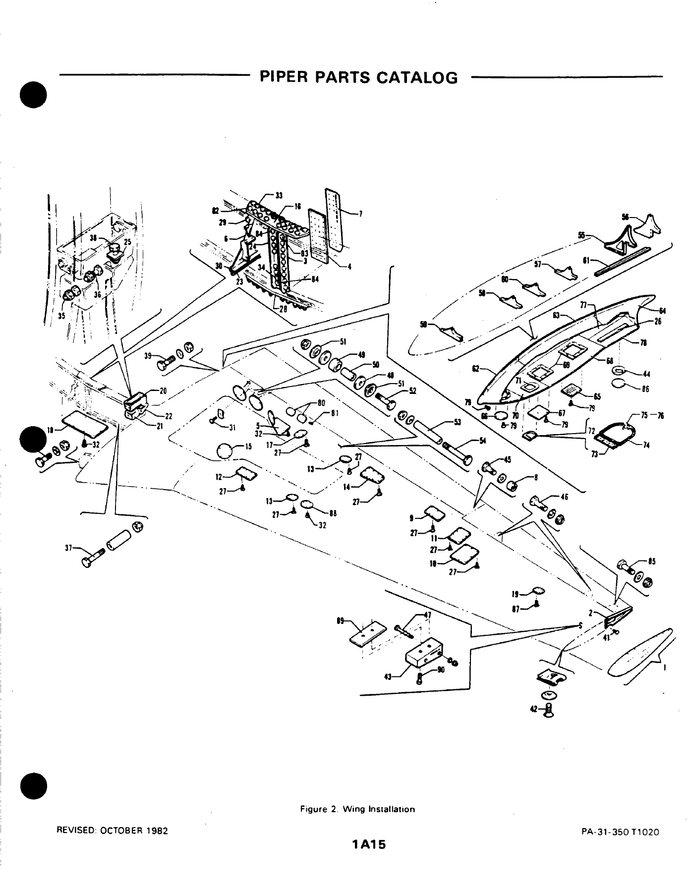
Fourteen major sections hold the airplane. Sections I through XIII each pair an illustration with an indented parts list. Section XIV covers placards and exterior stencils plus optional-equipment kits, repair kits, and special tools. A numerical index sits at Aerofiche grid 3A4.
List columns are Figure and Index Number, Part Number, Code, Nomenclature, No. Req., and Serial Numbers Affected. Indentation with asterisks shows next-higher assembly: one asterisk is one indent, two asterisks two indents. Ordering an unindented assembly brings the indented children; ordering a mid-level assembly brings only what sits under it. AR in the quantity column means as required. Letter codes printed on the grid before each list flag special use—navigation or strobe lights, pilot door, auxiliary outboard fuel cells, pneumatic de-ice, cargo door, Cleveland standard versus heavy-duty wheels, and similar installation differences. Commercial attaching hardware (nuts, bolts, screws) is listed for convenience with the AN, MS, or NAS number after the name; Piper notes those items are not generally supplied by the factory.
The introduction is explicit: under no circumstances shall this catalog be used for rigging and installation. Identify the part here, then use the appropriate maintenance publication for fit and procedure.
Power plant and related hardware shown in the lists
Figure 71 (Power Plant Installation) names the engines as Lycoming left T10-540-J2B and right LT10-540-J2B, obtained from Lycoming Division-Avco Corporation, Williamsport. The same figure lists Hartzell three-blade propeller assemblies HC-E3YR-2ATF/FC8468-6R (left) and HC-E3YR-2ALTF/FJC8468-6R (right), matching spinner assemblies, Hartzell governors F-6-24Z and F-6-24LZ, engine mounts, heat shields, induction air doors, turbocharger housing insulation blankets, exhaust-gas-temperature probes, oil-temperature bulbs, and drain and tail-pipe hardware. Later power-plant figures break out engine baffles, oil cooler and breather, propeller synchrophaser, engine controls, cowls, cowl-flap actuation, nacelles, and nacelle locker doors.
Chapters Covered
- Figure 1 – View of Complete Airplane
- Section I Wing Group – Wing Installation; Wing Panel Inboard and Outboard Parts; Leading Edge Assembly; Leading Edge Spar; Rear Spar; Aileron Assembly; Flap Assembly
- Section II Fuselage Group – Fuselage Assembly and upper/lower cabin, forward, center, rear, and aft sections; Pilot-door fuselage frame; Cargo-door fuselage frame; Floorboard; Structure Sta. 57–215 and Sta. 215–244; Windshield; Emergency-exit window; Cabin windows; Upper and lower cabin entrance doors; Forward baggage door; Cargo door; Pilot door (installation and complete assembly)
- Section III Tail Surfaces Group – Tail Surfaces Installation; Fin; Rudder; Stabilizer; Elevator
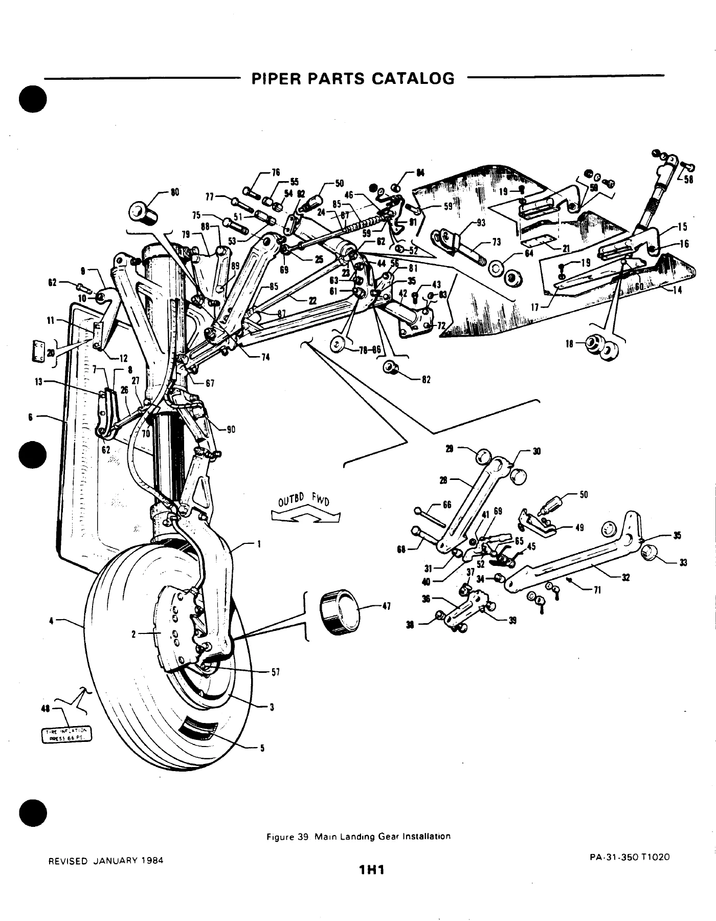
- Section IV Landing Gear Group – Main landing gear and strut; Cleveland standard and heavy-duty main wheels and brakes; Nose landing gear, strut, and wheel; Nose-gear steering; Brake system and dual brakes; Master cylinder and parking-brake valve; Emergency gear extension
- Section V Cabin Equipment Group – Commuter and cargo furnishings; Interior finishing, headliner, carpet, privacy curtain; Forward baggage finishing; Crew seat; 3rd/4th seats; 5th–9th seats; 10th/11th seats
- Section VI Instruments Group – Instrument panel and dual panel; Air and fluid lines; Dual instrument air; Instrument pressure; Static pressure; Tachometer shaft
- Section VII Power Plant Group – Power plant; Engine baffles; Oil cooler and breather; Three-blade propeller; Propeller synchrophaser; Engine controls; Cowls and cowl-flap mechanism; Nacelle and locker door
- Section VIII Fuel System Group – Left and right engine fuel systems; Fuel flow and pressure gauge; Fuel-system components and controls; Main and auxiliary fuel cells and liners
- Section IX Control System Group – Pedestal and pedestal control; Aileron, rudder, and elevator controls and trim; Flap control; Control wheel; Rudder pedals
- Section X Hydraulic System Group – Forward and aft hydraulics; Pumps; Wiebel components and Powerpak assembly/components; Landing-gear selector
- Section XI Environmental Group – Heater and defroster, heater assembly and components; Ventilation, distribution ducts, cabin exhaust vent and blower; Air-conditioning evaporator, Freon system, condenser and scoop; Forward and aft pneumatic de-icing; Oxygen system
- Section XII Electrical System Group – Forward and aft electrical; Instrument-panel electrical; Primary and auxiliary power; Switch and circuit-breaker system; Overhead switch panel; Landing lights; Propeller electrical de-icer; Windshield wiper; Strobe lights
- Section XIII Electronics Group – Narco ELT; Antenna cable, speaker, static wick, ramp hailer and microphone; Bendix RDR-230 HP radar; King KAP-200 / KFC-200 autopilot and flight director; Century 41 autopilot and flight director
- Section XIV Miscellaneous Group – Placards and exterior stencils; Optional equipment kits, repair kits, and special tools
- Numerical Index
Taken as a whole, the Piper PA-31-350 T1020 Illustrated Parts Catalog 761-775 1982-1984 gives a parts planner or technician the illustrated breakdown of every major group on the commuter/cargo T1020: skins, spars, fillets and access plates on the wing; frames, doors, windshield and floor structure in the fuselage; empennage surfaces; Cleveland wheel and brake variants on the gear; crew and passenger seats in both cabin layouts; instruments and their air/static lines; the Lycoming/Hartzell power plants and nacelles; main and auxiliary fuel cells; flight-control cables, pulleys and trim; the Wiebel hydraulic powerpak; Janitrol-related heater kits called out in the miscellaneous lists; electrical generation and lighting; and the factory-installed avionics options named above. Each illustration is keyed to Piper part numbers so an order can be written without guessing the next-higher assembly.
Wheels, brakes, and other configuration notes visible in the lists
Main-gear pages distinguish Cleveland wheel 40-130 with brake 30-95A from heavy-duty wheel 40-141 with brake 30-123. Tires listed include 6.50 x 10, 8-ply B. F. Goodrich, McCreary Airhawk, and Goodyear Flight Custom II. Strut assemblies change by serial block (31-8253001 to 31-8353007 versus 31-8453001 and up) and by which Cleveland combination is installed. Gear-lock hardware changes from rod assemblies on early 1982 serials to cable assemblies from 31-8353001 up. Codes also send the reader to later figures when navigation/strobe lights, auxiliary fuel cells, a pilot door, a cargo door, or pneumatic de-ice boots are present.
Paint, kits, and ordering notes
Standard paint charts list exterior acrylic-lacquer colors (Madrid Red, Bahama Blue, Las Vegas Gold, Dakota Black, Ocala Orange, Juneau White, Baja Yellow, Lime Green, Saffron, Claret, Firethorn, Dark Blue, Buckskin, Hickory Brown, Silver, Sandalwood Tan, Platinum Gray) with manufacturer numbers and Piper quart/gallon part numbers, plus Titanine thinners. A second chart covers Dupont Imron polyurethane enamels and primers with catalyst, reducer, retarder, accelerator, and fisheye eliminator. Section XIV and the miscellaneous lists include optional-equipment kits, repair kits, special tools, and items such as a Janitrol heater pressure-check kit. Shortages must be claimed within three days of receipt; returned goods require written permission and prepaid freight. Damage in transit is a carrier claim, not a factory liability. Piper had ceased Aerofiche production by the later revisions; the catalog notes that parts-catalog subscriptions were then offered on CD-ROM or DVD through Avantext.
Identify the correct T1020 part before you order
The Piper PA-31-350 T1020 Illustrated Parts Catalog 761-775 1982-1984 supports parts research, inventory planning, and purchase-order writing for the 1982–1984 T1020 serials listed above. Exploded views and indented lists let you move from a visible assembly—wing fillet, main-gear strut, Hartzell spinner, Wiebel powerpak, cabin seat, or heater plenum—to the Piper number, attaching hardware, quantity per aircraft or per assembly, and the serials that use that number. Using the right illustration and the Serial Numbers Affected column avoids mixing early-1982 rod-lock gear hardware with later cable-lock parts, or ordering a standard Cleveland wheel when the airframe has the heavy-duty pair. That accuracy matters because the T1020 shares a type certificate with other PA-31-350 airplanes but uses its own part applications, cabin layouts (commuter versus cargo), and option codes. Instant PDF delivery after payment: no shipping wait, readable on any device, and printable for the hangar bench or the parts counter. This catalog identifies parts only; it does not replace the service manual for rigging, installation, or adjustment.
Reviews
There are no reviews yet.