★ TRUSTED BY 321,897+ PROFESSIONALS WORLDWIDE
🏢
Trusted Business
Verified & Licensed
🛡️
Virus Free Files
100% Safe Downloads
🔒
Secure Payment
SSL Protected
Instant Delivery
Available Immediately
Sale!

Piper PA-32 Cherokee Six Lance Illustrated Parts Catalog 753-689 1966-1979

Original price was: $32.95.Current price is: $18.95.

Piper 753 689 illustrated parts catalog for PA-32-260, PA-32-300, and PA-32R-300 Cherokee Six and Lance airplanes, with figure-indexed replacement parts, serial-number effectivity, paint numbers, and a numerical index through the June 10, 2009 revision.

Instant PDF Download
Available immediately
💾
Save to Your Device
Download & keep forever
🛡️
Antivirus Scanned
100% virus-free
🌍
Trusted Worldwide
175,000+ customers

Description

Piper PA-32 Cherokee Six Lance Illustrated Parts Catalog 753-689 1966-1979

This Piper PA-32 Cherokee Six Lance Illustrated Parts Catalog 753-689 1966-1979 is the illustrated replacement-parts listing for the PA-32-260 Cherokee Six, PA-32-300 Cherokee Six, and PA-32R-300 Cherokee Lance. Piper Aircraft Corporation issued the catalog as part number 753 689 on June 27, 1975 and kept it current with dated revisions through PR061009 dated June 10, 2009. Each figure pairs an exploded drawing with a parts list that shows Piper part number, nomenclature, units per assembly, effectivity codes, and serial numbers affected so a technician can order the correct left- or right-hand item for a given airframe.

File Details

  • Manual type: Illustrated parts catalog
  • Brand / models: Piper PA-32-260, PA-32-300, PA-32R-300 (Cherokee Six and Cherokee Lance); PA-32S-300 seaplane items appear where coded
  • Document number: 753 689
  • Original issue: June 27, 1975
  • Latest listed revision: 753 689 (PR061009) dated June 10, 2009
  • Language: English
  • Page count: 637
  • File format: PDF

Aircraft and Serial Coverage

A dedicated serial-number chapter tells the reader which production years and serial blocks this Piper PA-32 Cherokee Six Lance Illustrated Parts Catalog 753-689 1966-1979 actually covers. Keep those ranges in view when matching a wing, door, tank, or landing-gear item, because many assemblies change at mid-year serial breaks.

  • PA-32-260 Cherokee Six: 32-1 through 32-1110 (1966–1968); 32-1111 through 32-1250 (1969 B); 32-1251 through 32-1320 (1970 C); 32-7100001 through 32-7100038 (1971 D); 32-7200001 through 32-7200055 (1972 E); then 32-7300001 through 32-7800008 for 1973–1978
  • PA-32-300 Cherokee Six: 32-40000 through 32-40565 (1967–1968); 32-40566 through 32-40850 (1969 B); 32-40851 through 32-41018 (1970 C); 32-7140001 through 32-714086 (1971 D); 32-7240001 through 32-7240147 (1972 E); then 32-7340001 through 32-7940290 for 1973–1979
  • PA-32R-300 Cherokee Lance: 32R-7680001 through 32R-7680538 (1976); 32R-7780001 through 32R-7780549 (1977); 32R-7880001 through 32R-7880068 (1978)
  • PA-32S-300 seaplane parts: are coded in several wing, enclosure, and float figures (example serial band 32S-40000 to 32S-7240147)

The catalog itself warns buyers to specify model and serial number on every order. Figure codes such as U, T, M, A, K, and J further restrict a line item to fixed-gear Six, late PA-32-300, retractable Lance, seaplane, or a narrow serial slice.

Complete PDF Bookmark Tree

Complete Bookmarks

The complete bookmarks in the “Piper PA-32 Cherokee Six Lance Illustrated Parts Catalog 753-689 1966-1979” are as follows:

753-689 – CHEROKEE PARTS CATALOG – PA-32-260/PA-32-300/PA-32R-300p. 1
REVISIONS STATUSp. 2
INTRODUCTIONp. 3
HOW TO IDENTIFY A PART IF YOU KNOW WHAT IT LOOKS LIKE AND KNOW WHERE IT IS LOCATEDp. 4
HOW TO ORDER PARTSp. 4
GENERAL INFORMATIONp. 4
PA-32 AND PA-32R SERIAL NUMBER INFORMATIONp. 5
STANDARD PAINT CHARTp. 6
TABLE OF CONTENTSp. 8
FIGURE 1. VIEW OF COMPLETE AIRPLANEp. 13
SECTION I – WING GROUPp. 14
FIGURE 2. WING INSTALLATIONp. 14
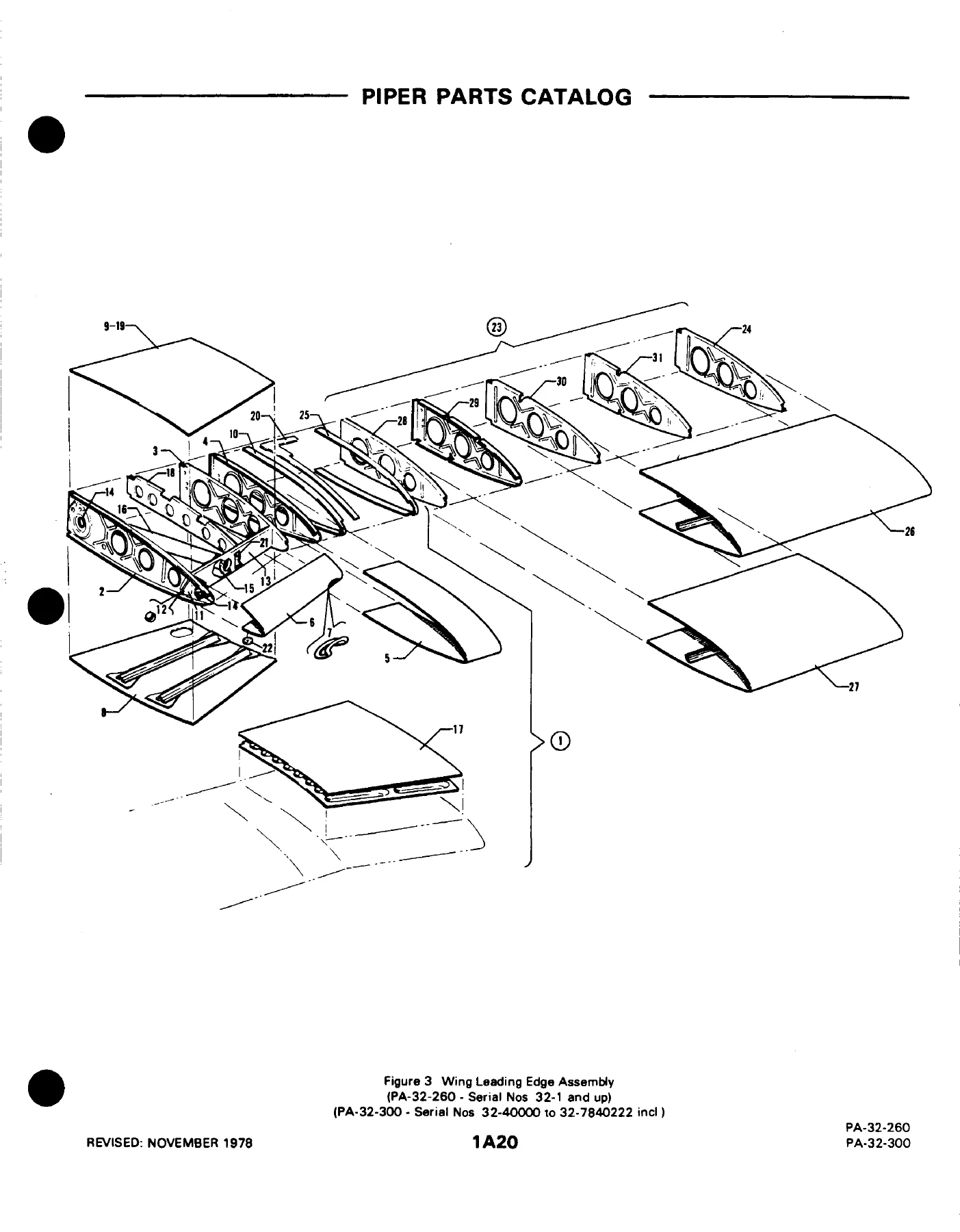
FIGURE 3. WING LEADING EDGE ASSEMBLY (PA-32-260 S/N 32-1 AND UP, PA-32-300 S/N 32-40000 TO 32-7840222 INCL.)p. 20
FIGURE 3A. WING LEADING EDGE ASSEMBLY (PA-32-300 S/N 7940001 AND UP, PA-32R-300 S/N 32R-7680001 AND UP)p. 24
FIGURE 4. WING TRAILING EDGE ASSEMBLY (PA-32-260/300)p. 27
FIGURE 5. WING TRAILING EDGE ASSEMBLY (PA-32R-300)p. 31
FIGURE 6. FLAP ASSEMBLYp. 35
FIGURE 7. AILERON ASSEMBLYp. 38
SECTION II – FUSELAGE GROUPp. 42
FIGURE 8. COMPLETE FUSELAGEp. 42
FIGURE 9. UPPER FORWARD COCKPIT ASSEMBLY (PA-32-260/300)p. 50
FIGURE 10. UPPER FORWARD COCKPIT ASSEMBLY (PA-32R-300)p. 55
FIGURE 11. UPPER CENTER COCKPIT ASSEMBLYp. 59
FIGURE 12. UPPER AFT COCKPIT ASSEMBLYp. 66
FIGURE 13. LOWER FOWARD COCKPIT ASSEMBLYp. 70
FIGURE 14. LOWER AFT COCKPIT ASEMBLYp. 75
FIGURE 15. FUSELAGE AFT SECTIONp. 79
FIGURE 16. ENCLOSURE INSTALLATION (PA-32-260 S/N 32-1 TO 32-7200055 INCL., PA-32-300 S/N 32-40000 TO 32-7240147 INCL.)p. 83
FIGURE 17. ENCLOSURE INSTALLATION (PA-32-260 S/N 32-7300001 TO 32-7300076 INCL., PA-32-300 S/N 32-7340001 TO 32-7340201 INCL.)p. 88
FIGURE 18. ENCLOSURE INSTALLATION (PA-32-260 S/N 32-7400001 AND UP, PA-32-300 S/N 32-7440001 AND UP, PA-32R-300 S/N 32R-7680001 AND UPp. 92
FIGURE 19. FORWARD CABIN DOOR (PA-32-260 S/N 32-1 TO 32-7600001 INCL., PA-32-300 S/N 32-40000 TO 32-7640029 INCL., PA-32R-300 S/N 32R-7680001 TO 32R-7680013 INCL.)p. 96
FIGURE 19A. FORWARD CABIN DOOR (PA-32-260 S/N 32-7600002 AND UP, PA-32-300 S/N 32-7640030 AND UP, (PA-32R-300 S/N 32R-7680014 AND UP)p. 102
FIGURE 20. AFT CABIN DOORp. 106
FIGURE 21. FORWARD BAGGAGE DOORp. 112
FIGURE 22. AFT CARGO DOOR (PA-32-260 S/N 32-1 TO 32-7300076 INCL., PA-32-300 S/N 32-40000 TO 32-7340201 INCL.)p. 115
FIGURE 23. AFT CARGO DOOR (PA-32-260 S/N 32-7400001 AND UP, PA-32-300 S/N 32-7440001 AND UP, PA-32R-300 S/N 32R-7680001 AND UP)p. 119
FIGURE 24. COCKPIT FINISHING INSTALLATIONp. 125
FIGURE 24A. WINDOW CURTAIN INSTALLATION (PA-32-260 S/N 32-7700001 AND UP, PA-32-300 S/N 32-7740001 AND UP, PA-32R-300 S/N 32p. 143
FIGURE 25. CARPET INSTALLATIONp. 147
FIGURE 26. HEADLINER INSTALLATION (PA-32-260 S/N 32-1 TO 32-7300076 INCL., PA-32-300 S/N 32-40000 TO 32-73040201 INCL.)p. 160
FIGURE 27. HEADLINER AND FORWARD FRESH AIR DUCT INSTALLATION (PA-32-260 S/N 32-7400001 AND UP, PA-32-300 S/N 32-7440001 AND UP)p. 163
FIGURE 28. AFT FRESH AIR DUCT INSTALLATION (PA-32-260 S/N 32-7400001 AND UP, PA-32-300 S/N 32-7440001 AND UP, PA-32R-300 S/Np. 166
FIGURE 29. SEATS INSTALLATIONp. 171
FIGURE 30. VERTICALLY ADJUSTABLE FRONT SEAT ASSEMBLY (PA-260 S/N 32-1251 TO 32-7400009 INCL., PA-32-300 S/N 32-7440027 INCL.)p. 182
FIGURE 31. VERTICALLY ADJUSTABLE FRONT SEAT ASSEMBLY (PA-32-260 S/N 32-7400010 AND UP, PA-32-300 S/N 32-7440028 AND UP, PA-32R-300 S/N 32R-7680001 AND UPp. 185
FIGURE 32. 7TH SEAT INSTALLATIONp. 190
FIGURE 32A. AFT FACING SEAT ASSEMBLY – CENTER (PA-32-260 S/N 32-7700001 AND UP, PA-32-300 S/N 32-7740001 AND UP, PA-32R-300 AND UPp. 195
FIGURE 32B. CLUB SEATING INSTALLATION (PA-32-260 S/N 32-7700001 AND UP, PA-32-300 S/N 32-77400001 AND UP, PA-32R-300 S/N 32R-7780001 AND UPp. 198
FIGURE 33. INSTRUMENT PANEL INSTALLATION (PA-32-260 S/N 32-1 TO 32-1110 INCL., PA-32-300 S/N 32-40000 TO 32-40565 INCL.)p. 201
FIGURE 34. INSTRUMENT PANEL INSTALLATION (PA-32-260 S/N 32-1111 AND UP, PA-32-300 S/N 32-40566 AND UP, PA-32R-300 S/N 32R-7680001 AND UPp. 205
FIGURE 35. VACUUM SYSTEM INSTALLATION (PA-32-260 S/N 32-1 TO 32-896 INCL., PA-32-300 S/N 32-40000 TO 32-40000 TO 32-40292 INCL.)p. 214
FIGURE 36. VACUUM SYSTEM INSTALLATION (PA-32-260 S/N 32-897 AND UP, PA-32-300 S/N 32-40293 AND UP, PA-32R-300 S/N 32R-7680001 AND UPp. 218
FIGURE 37. PITOT STATIC SYSTEM INSTALLATIONp. 221
FIGURE 38. CABIN HEAT AND DEFROSTER SYSTEM (PA-32-260/300)p. 225
FIGURE 39. CABIN HEAT AND DEFROSTER SYSTEM (PA-32R-300)p. 230
FIGURE 40. CABIN OVERHEAD AIR VENT INSTALLATION (PA-32-260 S/N 32-1 TO 32-1320 INCL., PA-32-300 S/N 32-400000 TO 32-41018 INCL.)p. 234
FIGURE 41. CABIN OVERHEAD AIR VENT INSTALLATION (PA-32-260 S/N 32-7100001 TO 32-7300076 INCL., PA-32-300 S/N 32-7140001 TO 32-7340201 INCL.)p. 237
FIGURE 42. AIR CONDITIONING COMPRESSOR, REFRIGERANT LINES AND ALTERNATOR INSTALLATION (PA-32-300 S/N 32-40853, 32-7240056 AND UP, PA-32R-300 S/N 32R-7680001 AND UPp. 241
FIGURE 43. AIR CONDITIONING DUCT AND EVAPORATOR INSTALLATION (PA-32-300 S/N 32-40853, 32-7240056 AND UP, PA-32R-300 S/N 32R-7680001 AND UPp. 245
FIGURE 44. AIR CONDITIONING CONDENSER INSTALLATION (PA-32-300 S/N 32-40853, 32-7240056 AND UP, PA-32R-300 S/N 32R-7680001 AND UPp. 248
SECTION III – TAIL SURFACES GROUPp. 252
FIGURE 45. TAIL SURFACES INSTALLATIONp. 252
FIGURE 46. STABILATOR ASEMBLYp. 256
FIGURE 47. FIN AND RUDDER ASSEMBLIESp. 259
SECTION IV – CHASSIS GROUPp. 264
FIGURE 48. NOSE GEAR INSTALLATION (PA-32-260/300)p. 264
FIGURE 49. NOSE GEAR STRUT ASSEMBLY (PA-32-260/300)p. 268
FIGURE 50. NOSE GEAR INSTALLATION (PA-32R-300)p. 272
FIGURE 51. NOSE GEAR ASSEMBLY (PA-32R-300)p. 277
FIGURE 52. NOSE WHEEL ASSEMBLY (CLEVELAND)p. 282
FIGURE 52A. NOSE WHEEL ASSEMBLY (MCCAULEY)p. 285
FIGURE 52B. NOSE WHEEL ASSEMBLY (MCCAULEY)p. 288
FIGURE 53. MAIN GEAR INSTALLATION (PA-32-260/300)p. 291
FIGURE 54. MAIN GEAR INSTALLATION (PA-32R-300)p. 295
FIGURE 55. MAIN GEAR ASSEMBLY (PA-32R-300)p. 299
FIGURE 56. MAIN WHEEL ASSEMBLYp. 303
FIGURE 57. EDO FLOAT INSTALLATION (PA-32S-300)p. 306
FIGURE 58. WHEEL FAIRING INSTALLATION (PA-32-260 S/N 32-1 TO 32-7700023 INCL., PA-32-300 S/N 32-40000 TO 32-7740113 INCL.)p. 310
FIGURE 58A. WHEEL FAIRING INSTALLATION (PA-32-260 S/N 32-7800001 AND UP, PA-32-300 S/N 32-7840001 AND UP)p. 313
FIGURE 59. STRUT FAIRING INSTALLATION (PA-32-260/300)p. 317
FIGURE 60. HAND BRAKE INSTALLATIONp. 320
FIGURE 61. BRAKE ASSEMBLYp. 324
FIGURE 62. LANDING GEAR DOOR INSTALLATION (PA-32R-300)p. 327
FIGURE 63. TOE BRAKE INSTALLATIONp. 330
FIGURE 64. TOE BRAKE MASTER CYLINDER ASSEMBLYp. 333
SECTION V – HYDRAULIC GROUPp. 336
FIGURE 65. HYDRAULIC SYSTEM INSTALLATION (PA-32R-300)p. 336
SECTION VI – POWER PLANT GROUPp. 342
FIGURE 66. POWER PLANT INSTALLATION (PA-32-260)p. 342
FIGURE 67. POWER PLANT INSTALLATION (PA-32-300 S/N 32-40000 TO 32-7540198 INCL.)p. 346
FIGURE 67A. POWER PLANT INSTALLATION (PA-32-300 S/N 32-7640001 AND UP)p. 350
FIGURE 68. POWER PLANT INSTALLATION (PA-32R-300)p. 354
FIGURE 69. ENGINE EXHAUST SYSTEM INSTALLATION (PA-32-260)p. 358
FIGURE 70. ENGINE EXHAUST SYSTEM INSTALLATION (PA-32-300 S/N 32-40000 TO 32-7540198 INCL.)p. 361
FIGURE 71. ENGINE EXHAUST SYSTEM INSTALLATION (PA-32-300 S/N 32-7640001 AND UP, PA-32R-300 S/N 32R-7680001 AND UP)p. 364
FIGURE 72. ENGINE BAFFLE INSTALLATION (PA-32-260)p. 367
FIGURE 73. ENGINE BAFFLE INSTALLATION (PA-32-300/R300p. 370
FIGURE 74. ENGINE COWL ASSEMBLY (PA-32-260/300)p. 373
FIGURE 75. ENGINE COWL ASSEMBLY (PA-32R-300)p. 378
FIGURE 76. ENGINE CONTROLS INSTALLATION (PA-32-260 S/N 32-1 TO 32-1110 INCL.)p. 381
FIGURE 77. ENGINE CONTROLS INSTALLATION (PA-32-260 S/N 32-1111 TO 32-7200055 INCL.)p. 384
FIGURE 78. ENGINE CONTROLS INSTALLATION (PA-32-260 S/N 32-7300001 AND UP)p. 388
FIGURE 79. ENGINE CONTROLS INSTALLATION (PA-32-300 S/N 32-40000 TO 32-40565 INCL.)p. 392
FIGURE 80. ENGINE CONTROLS INSTALLATION (PA-32-300 S/N 32-40566 AND UP)p. 396
FIGURE 81. ENGINE CONTROLS INSTALLATION (PA-32R-300)p. 401
FIGURE 82. CONSTANT SPEED PROPELLER INSTALLATION (PA-32-260 S/N 32-1 TO 32-1110 INCL.)p. 406
FIGURE 83. CONSTANT SPEED PROPELLER INSTALLATION (PA-32-260 S/N 32-1111 TO 32-7200055 INCL.)p. 409
FIGURE 84. PROPELLER ASSEMBLYp. 413
SECTION VII – FUEL SYSTEM GROUPp. 417
FIGURE 85. FORWARD FUEL SYSTEM INSTALLATION (PA-32-260)p. 417
FIGURE 86. AFT FUEL SYSTEM INSTALLATION (PA-32-260)p. 422
FIGURE 87. FORWARD FUEL SYSTEM INSTALLATION (PA-32-300/R-300)p. 427
FIGURE 88. AFT FUEL SYSTEM INSTALLATION (PA-32-300 S/N 32-40000 TO 32-78400222 INCL.)p. 431
FIGURE 89. AFT FUEL SYSTEM INSTALLATION (PA-32-300 S/N 32-7940001 AND UP, PA-32R-300 S/N 32R-7680001 AND UPp. 435
FIGURE 90. FUEL TANK ASSEMBLIES (PA-32-260 S/N 32-1 AND UP, PA-32-300 S/N 32-40000 TO 32-7840222 INCL.)p. 439
FIGURE 91. FUEL TANK ASSEMBLIES (PA-32-300 S/N 32-7940001 AND UP, PA-32R-300 S/N 32R-7680001 AND UPp. 442
SECTION VIII – CONTROL SYSTEM GROUPp. 446
FIGURE 92. CONTROL SYSTEM INSTALLATIONp. 446
FIGURE 93. FLAP CONTROL INSTALLATIONp. 451
FIGURE 94. STABILATOR TRIM INSTALLATIONp. 455
FIGURE 95. RUDDER TRIM MECHANISM INSTALLATIONp. 459
FIGURE 96. CONTROL WHEEL INSTALLATIONp. 462
FIGURE 97. RUDDER PEDAL INSTALLATIONp. 467
SECTION IX – ELECTRICAL SYSTEM GROUPp. 470
FIGURE 98. ELECTRICAL SYSTEM INSTALLATION (PA-32-260/300)p. 470
FIGURE 99. ELECTRICAL SYSTEM INSTALLATION (PA-32R-300)p. 474
FIGURE 100. INSTRUMENT PANEL ELECTRICAL INSTALLATION (PA-32-260 S/N 32-1 TO 32-1110 INCL., PA-32-300 S/N 32-40000 TO 32-40565 INCL.)p. 478
FIGURE 101. INSTRUMENT PANEL ELECTRICAL INSTALLATION (PA-32-260 S/N 32-1111 AND UP, PA-32-300 S/N 32-40566 AND UP, PA-32R-300 S/N 32R-7680001 AND UP)p. 481
FIGURE 102. BATTERY BOX INSTALLATIONp. 485
FIGURE 103. ALTERNATOR INSTALLATION (CHRYSLER)p. 488
FIGURE 104. EXTERNAL POWER SUPPLY INSTALLATION (PA-32-260/300)p. 493
FIGURE 105. EXTERNAL POWER SUPPLY INSTALLATION (PA-32R-300)p. 496
FIGURE 106. STROBE LIGHTS INSTALLATION (PA-32-260/300)p. 499
FIGURE 107. AIR CONDITIONING ELECTRICAL INSTALLATION (PA-32-300 S/N 32-40853, 32-740056 AND UP, PA-32R-300 S/N 32R-7680001 AND UPp. 502
FIGURE 108. ALTERNATOR ASSEMBLY (PRESTOLITE) (PA-32-300 S/N 32-40853, 32-7240056 AND UP, PA-32R-300 S/N 32R-7680001 AND UPp. 505
SECTION X – ELECTRONICS GROUPp. 509
FIGURE 109. PIPER PM-1 MARKER BEACON INSTALLATION (PA-32-260/300)p. 509
FIGURE 110. PIPER AUTOMATIC LOCATOR (ELT) INSTALLATION (GARRET MFG LTD.)p. 512
FIGURE 110A. PIPER AUTOMATIC LOCATOR (ELT) INSTALLATION (COMMUNICATIONS COMPONENTS CORP.)p. 515
FIGURE 110B. PIPER AUTOMATIC LOCATOR (ELT) INSTALLATION (NARCO AVIONICS)p. 518
FIGURE 111. RADIO, ANTENNA SYSTEM AND STATIC WICKS INSTALLATIONp. 521
FIGURE 112. RADIO JUNCTION BOXESp. 525
FIGURE 113. ELECTRIC TRIM INSTALLATIONp. 529
FIGURE 114. AUTOFLITE LL INSTALLATION (PA-32-260 S/N 32-1 TO 31-1320 INCL., PA-32-300 S/N 32-40000 TO 32-41018 INCL.)p. 532
FIGURE 115. AUTOFLITE LL INSTALLATION (PA-32-260 S/N 32-7100001 AND UP, PA-32-300 S/N 32-71400001 AND UP, PA-32R-300 S/N 32R-7680001 AND UP)p. 535
FIGURE 116. AUTOCONTROL II INSTALLATION (PA-32-260/300)p. 538
FIGURE 117. AUTOCONTROL III AND III B INSTALLATIONp. 541
FIGURE 118. ALTIMATIC LLL C INSTALLATION (PA-32-260 S/N 32-451 TO 32-1110 INCL., PA-32-300 S/N 32-40000 TO 32-40565 INCL.)p. 544
FIGURE 119. ALTIMATIC LLL C INSTALLATION (PA-32-260 S/N 32-7500001 AND UP, PA-32-300 S/N 32-7540001 TO 32-7840222 INCL., PA-32R-300 S/N 32R-7680001 AND UP)p. 548
FIGURE 119A. ALTIMATIC LLL C INSTALLATION (PA-32-300 S/N 32-7940001 AND UP)p. 553
FIGURE 120. RADAR SYSTEM INSTALLATION (PA-32-260 S/N 32-7600001 AND UP, PA-32-300 S/N 32-7640001 AND UP, PA-32R-300 S/N 32R-7680001 AND UP)p. 557
FIGURE 121. ENCODER INSTALLATION (NARCO – AR500 & UNITED – 5125-P3) (PA-32-260 S/N 32-7700001 AND UP, PA-32-300 S/N 32-7740001 AND UP, PA-32R-300 S/N 32R-7780001 AND UP)p. 560
FIGURE 122. RADAR SYSTEM INSTALLATION (32-300 S/N 32-7940063 AND UP)p. 563
RADIO INSTALLATION DRAWINGSp. 566
SECTION XI – MISCELLANEOUS GROUPp. 569
FIGURE 123. PLACARDS AND EXTERIOR STENCILS (PA-32-260 S/N 32-1 TO 32-1110 INCL., PA-32-300 S/N 32-40000 TO 32-40565 INCL.)p. 569
FIGURE 124. PLACARDS AND EXTERIOR STENCILS (PA-32-260 S/N 32-1111 AND UP, PA-32-300 S/N 32-40566 AND UP, PA-32R-300 S/N 32R-7680001 AND UP)p. 573
OPTIONAL EQUIPMENT KITS AND REPAIR KITSp. 580
NUMERICAL INDEXp. 585

How the Catalog Is Organized

Front matter explains figure-and-index numbering, the part-number column that must appear on orders, indented units-per-assembly quantities, the AR (as required) quantity, and serial-effectivity columns. Attaching hardware that is ordinary commercial stock is listed after the assembly name for convenience but is not generally supplied by Piper. Optional equipment is mixed into the same figure sequence rather than flagged with a separate “optional” stamp. A short “how to identify a part” path sends the reader from the complete-airplane view (Figure 1) to the table of contents, then to the illustration and the matching index line. Ordering instructions require model, serial, part number, name, type, quantity, and a shipping method. Returned-goods and shortage rules are printed in the same introductory block. A caution states the book is not to be used for rigging or installation.

Chapters Covered

  • Introduction, revisions status, serial-number information, standard paint chart
  • Section I Wing Group — complete airplane view; wing installation; leading-edge assemblies (early and late); trailing-edge assemblies (fixed-gear and Lance); flap assembly; aileron assembly
  • Section II Fuselage Group — complete fuselage; upper and lower cockpit assemblies; enclosure installations by serial block; forward cabin door (early and late); aft cabin door; forward baggage door; aft cargo door (early and late); cockpit finishing; window curtains; carpet; headliner and fresh-air ducts; seats, vertically adjustable front seats, 7th seat, aft-facing center seat, club seating; instrument panels; vacuum systems; pitot-static system; cabin heat and defroster; overhead air vents; air-conditioning compressor, ducts, evaporator, and condenser
  • Section III Tail Surfaces Group — tail surfaces installation; stabilator assembly; fin and rudder assemblies
  • Section IV Chassis Group — nose gear and strut (fixed-gear and Lance); Cleveland and McCauley nose wheels; main gear and main wheel; EDO float installation (PA-32S-300); wheel and strut fairings; hand brake and brake assembly; landing-gear doors (Lance); toe brake and master cylinder
  • Section V Hydraulic Group — hydraulic system installation (PA-32R-300)
  • Section VI Power Plant Group — power-plant installations by model and serial; exhaust systems; engine baffles; cowl assemblies; engine controls; constant-speed propeller installations and propeller assembly
  • Section VII Fuel System Group — forward and aft fuel systems; wing fuel tank assemblies (early tip/inboard tanks and later inboard/outboard tanks)
  • Section VIII Control System Group — control system; flap control; stabilator trim; rudder trim; control wheel; rudder pedals
  • Section IX Electrical System Group — airframe electrical installations; instrument-panel electrical; battery box; Chrysler and Prestolite alternators; external power; strobe lights; air-conditioning electrical
  • Electronics Group — PM-1 marker beacon; ELT installations (Garrett, Communications Components Corp., Narco); radio, antenna, and static wicks; radio junction boxes; electric trim; AutoFlite / AutoFlite II; Autocontrol II / III / III B; AltiMatic III / III C; radar altimeter; encoder; radar system; radio installation drawings
  • Miscellaneous Group — placards and exterior stencils; optional equipment kits and repair kits
  • Numerical Index — part number to figure-and-index lookup

Taken together, the figures give a technician a complete illustrated map of airframe structure, furnishings, landing gear, powerplant accessories, fuel cells, flight controls, electrical boxes, and factory-installed avionics kits. Each list carries attaching hardware, quantity, and the serial band that uses that dash number, which is the practical difference between guessing a part from a photograph and ordering the item Piper assigned to that airplane.

Illustrated Assemblies and Effectivity Coding

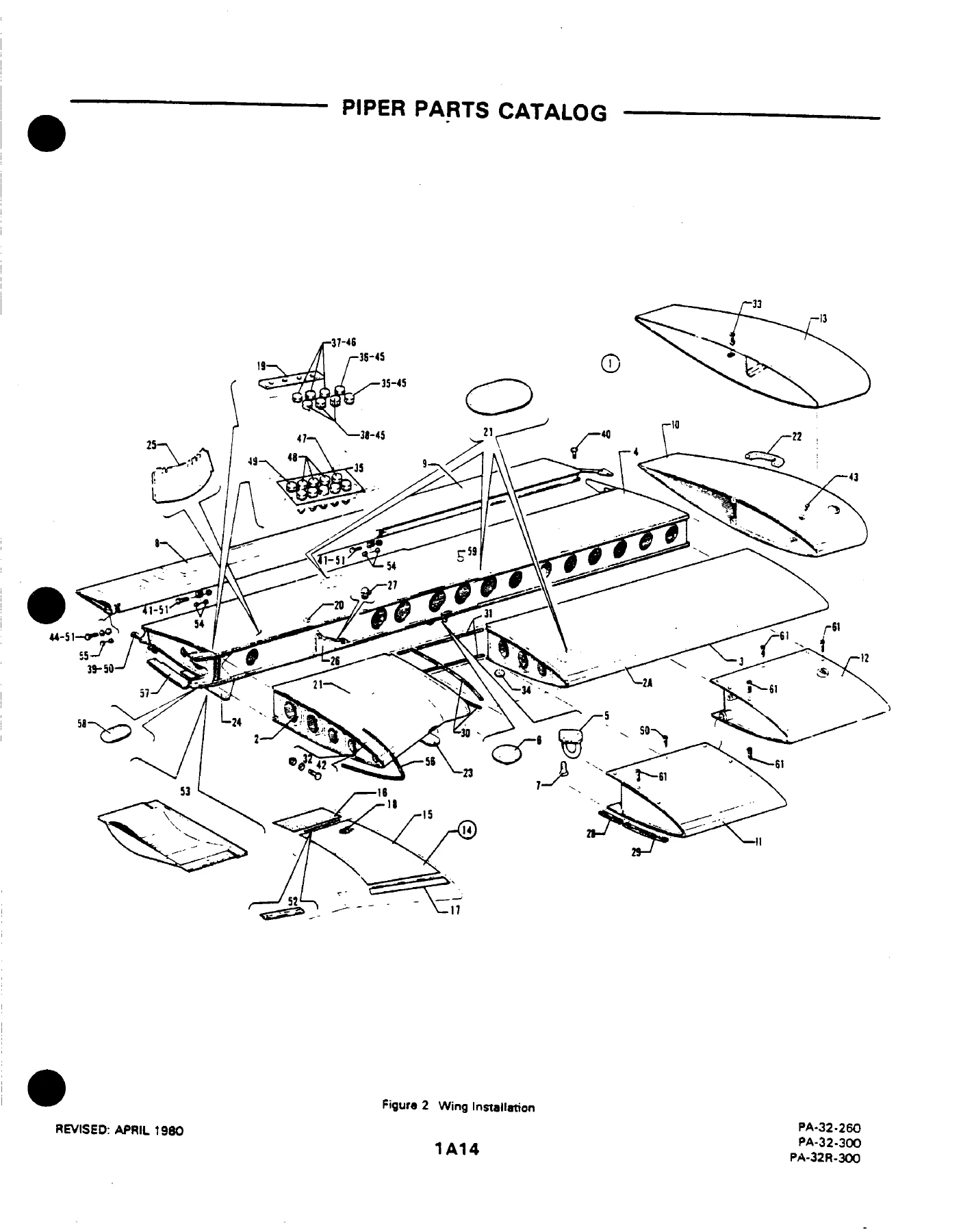
Figure 2 (wing installation) is typical of the catalog’s method. Left and right wing assemblies are listed under several drawing numbers (66600, 38404, 38121, 69555) with codes that split early Six wings from late PA-32-300 and Lance wings that include brake lines, fuel lines, pitot lines, inspection covers, and vent ducts. Leading-edge, trailing-edge, flap, and aileron assemblies point to their own figures. Fuel tanks appear as 65815 tip tanks and 63998 inboard tanks on early airplanes, then 95071 / 95070 inboard and outboard tanks on later PA-32-300 and PA-32R-300 airplanes. A code note withdraws Randolph sloshing compound 802 (Piper 757 572) from fuel-tank use and points the reader to the latest revision of Service Bulletin 251. Another note replaces nut 404 890 with 404 532 (MS21042-6) on a limited 1974–1975 serial band per Service Letter 745.

The same pattern repeats on landing gear. Fixed-gear Six airplanes use one nose-gear and main-gear figure set; Lance airplanes add retractable struts, gear doors, and a hydraulic-system figure. Nose wheels are split among Cleveland and two McCauley assemblies. Float hardware for the PA-32S-300 sits in its own figure. Power-plant figures separate the PA-32-260 installation from two PA-32-300 serial groups and the PA-32R-300 installation, then break exhaust, baffles, cowl, engine controls, and the constant-speed propeller into their own drawings so a spinner, governor, or control cable can be identified without ordering an entire engine change kit.

IMAGES PREVIEW

Piper PA-32 Cherokee Six Lance Illustrated Parts Catalog 753-689 1966-1979 — PDF page 1 preview
Piper PA-32 Cherokee Six Lance Illustrated Parts Catalog 753-689 1966-1979 — PDF page 14 preview
Piper PA-32 Cherokee Six Lance Illustrated Parts Catalog 753-689 1966-1979 — PDF page 20 preview

Standard Paint Chart and Finish Materials

Two paint charts list exterior acrylic-lacquer and Dupont Imron polyurethane colors with manufacturer numbers and Piper quart/gallon part numbers. Acrylic colors include Pontiac Red, Tampa Green, Newport Blue, Juneau White, Lakeland Blue, Orlando Green, Mocha Tan, Madrid Red, Dakota Black, Lincoln Gray, Nassau and Bimini Turquoise, Reno Gold, Ocala Orange base and top coats, Dallas Yellow, Beaumont Blue, Polar Gray, Monterey Maroon, Bahama Blue, Las Vegas Gold, Avocado, Lime Green, Baja Yellow, Denver Brown, Matador Red, Royal Blue, Hickory Brown, and Indian Silver, plus thinner 4179 402 / 1179 402. Polyurethane listings add Sage Green, Firethorn, Buckskin, Dark Blue, Platinum Gray, and Sandalwood Tan together with catalyst 192S, reducer 8485S, retarder 8100S, accelerator 189S, and Imron wash primer with matching thinners. Those numbers matter when matching a faded Six or Lance scheme or when ordering touch-up material under the same Piper stock number printed in this Piper PA-32 Cherokee Six Lance Illustrated Parts Catalog 753-689 1966-1979.

Avionics, Optional Kits, and Numerical Index

Later figures cover factory radio stacks, antennas, static wicks, junction boxes, electric trim, AutoFlite and Autocontrol series, AltiMatic III and III C, radar altimeter, altitude encoder, and a radar system on late PA-32-300 serials 32-7940063 and up. ELT installations are split by vendor: Garrett, Communications Components Corp., and Narco. The miscellaneous group lists placards and exterior stencils for early versus later serials, then optional equipment kits and repair kits. The closing numerical index runs part numbers back to figure-and-index locations so a number pulled from a tag, invoice, or removed part can be traced to its illustration without paging through every section.

Identify and Order the Correct Cherokee Six or Lance Part

Use this Piper PA-32 Cherokee Six Lance Illustrated Parts Catalog 753-689 1966-1979 when a wing skin, cabin door, gear actuator, fuel tank, flap, cowl, propeller spinner, or instrument-panel item must be ordered by Piper number instead of a generic description. Serial-coded lists prevent mixing early 32-1 hardware with 1979 PA-32-300 or 1976–1978 Lance retractable-gear parts. Correct part numbers and quantities reduce wasted orders and keep structural and systems replacements aligned with the airplane that is actually in the hangar.

The file is delivered as an instant PDF download after payment. There is no printed-book shipment and no waiting on media mail. Open it on a shop computer, tablet, or phone and print the figure you need at the bench. Keep the catalog with the airframe records so the next annual, tank reseal, gear overhaul, or interior refresh starts from the same illustrated list Piper published for these PA-32 and PA-32R airplanes.
Reviews

There are no reviews yet.

Be the first to review “Piper PA-32 Cherokee Six Lance Illustrated Parts Catalog 753-689 1966-1979”

What Our Customers Say

★★★★★ Live reviews from customers
Loading customer reviews...
0
    0
    Your Cart
    Your cart is emptyReturn to Shop
    🛒
    Recently Purchased
    🕒 verified order