★ TRUSTED BY 321,897+ PROFESSIONALS WORLDWIDE
🏢
Trusted Business
Verified & Licensed
🛡️
Virus Free Files
100% Safe Downloads
🔒
Secure Payment
SSL Protected
Instant Delivery
Available Immediately
Sale!

Piper Cherokee PA-28-140/150/160/180/235 & PA-28R-180/200 Illustrated Parts Catalog 753 582 – 2009

Original price was: $44.95.Current price is: $26.95.

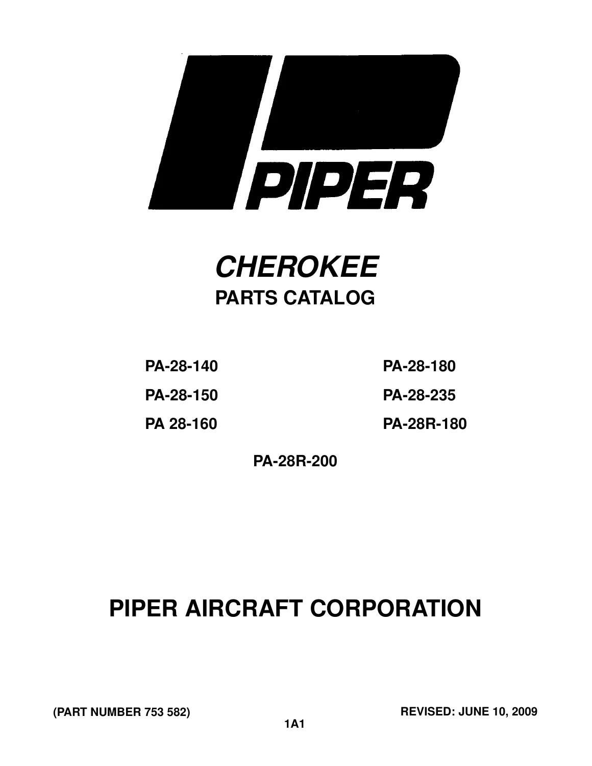
Illustrated Piper Cherokee parts catalog for PA-28-140, PA-28-150, PA-28-160, PA-28-180, PA-28-235, PA-28R-180 and PA-28R-200 aircraft. Part number 753 582, revised June 10, 2009, with exploded illustrations, replacement part numbers, nomenclature, quantities and serial-number applicability across major airframe and aircraft systems.

Instant PDF Download
Available immediately
💾
Save to Your Device
Download & keep forever
🛡️
Antivirus Scanned
100% virus-free
🌍
Trusted Worldwide
175,000+ customers

Description

Piper Cherokee PA-28 and PA-28R Illustrated Parts Reference

The Piper Cherokee PA-28-140/150/160/180/235 & PA-28R-180/200 Illustrated Parts Catalog 753 582 – 2009 is an extensive illustrated replacement-parts reference covering seven Cherokee and Cherokee Arrow model designations. Across 827 PDF pages, the catalog combines exploded component illustrations with corresponding parts lists so owners, maintainers and parts personnel can identify assemblies, individual components and the applicable part numbers for specific aircraft configurations.

The catalog is particularly valuable where the same general assembly changed through different production periods. Parts-list entries can include the figure and index number, Piper part number, application code, nomenclature, quantity required and serial numbers affected. This makes the document much more precise than identifying a component by appearance alone: the illustration establishes where the item fits in an assembly, while the associated listing shows the replacement-part identity and applicable aircraft range.

File Details

  • Manual type: Illustrated Parts Catalog
  • Brand: Piper Aircraft Corporation
  • Models: PA-28-140, PA-28-150, PA-28-160, PA-28-180, PA-28-235, PA-28R-180, PA-28R-200
  • Language: English
  • Pages: 827
  • File format: PDF
  • Part number: 753 582
  • Revision: June 10, 2009

Designed for Positive Replacement-Part Identification

The introductory instructions explain how the illustrated catalog is intended to be used. A technician can first locate the relevant area of the airplane, identify the appropriate catalog section, select an illustration covering that subgroup and then match the required component to its figure/index number. The corresponding parts-list entry provides the component nomenclature and part number. Assembly relationships are also represented in the nomenclature structure, helping distinguish a complete assembly from the individual pieces contained within it.

Serial-number applicability is a major part of the catalog. Dedicated introductory pages explain Piper serial-number formats and provide model-year serial information for the aircraft families covered. Throughout the individual parts lists, many components are tied to specific serial-number ranges, allowing the reader to distinguish changes that occurred during production rather than assuming every listed part applies to every PA-28 or PA-28R.

This is a parts-identification catalog rather than a rigging or installation manual. The catalog itself specifically instructs users not to use it for rigging and installation purposes. Its strength is detailed illustrated parts identification, assembly breakdowns, part-number lookup and configuration applicability.

Complete PDF Bookmark Tree

Complete Bookmarks

The complete bookmarks in the “Piper Cherokee PA-28-140/150/160/180/235 & PA-28R-180/200 Illustrated Parts Catalog 753 582 – 2009” are as follows:

753-582 – CHEROKEE PARTS CATALOG – PA-28-140/150/160/180/235/R-180/200p. 1
AEROFICHE EXPLANATIONp. 2
REVISIONSp. 2
INTRODUCTIONp. 3
GRID NUMBERINGp. 4
HOW TO IDENTIFY A PART IF YOU KNOW WHAT IT LOOKS LIKE AND KNOW WHERE IT IS LOCATEDp. 4
HOW TO ORDER PARTSp. 4
GENERAL INFORMATIONp. 4
PA-28 AND PA-28R SERIAL NUMBER INFORMATIONp. 5
PA-28/28R SERIAL NUMBER EXPLANATIONp. 7
STANDARD PAINT CHARTp. 8
TABLE OF CONTENTSp. 9
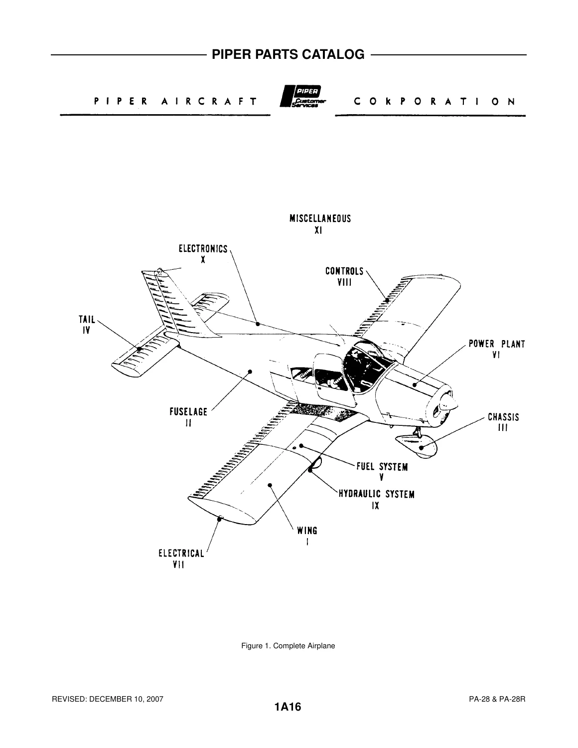
FIGURE 1. VIEW OF COMPLETE AIRPLANEp. 16
SECTION I – WING GROUPp. 16
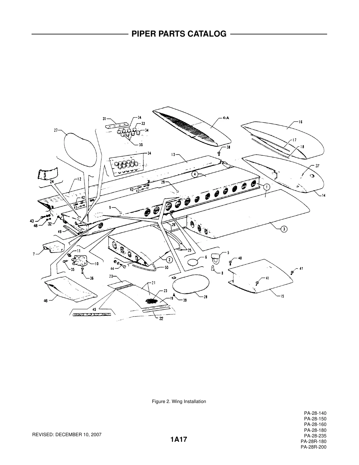
FIGURE 2. WING INSTALLATION (PA-28-140/150/160/180/235, PA-28R-180/200)p. 17
FIGURE 3. WING LEADING EDGE ASSEMBLY (PA-28-140/150/160/180/235, PA-28R-180/200)p. 22
FIGURE 4. WING TRAILING EDGE ASSEMBLY (PA-28-140/150/160/180/235)p. 25
FIGURE 5. WING TRAILING EDGE ASSEMBLY (PA-28R-180/200)p. 28
FIGURE 6. AILERON ASSEMBLY (PA-28-140/150/160/180/235, PA-28R-180/200)p. 31
FIGURE 7. FLAP ASSEMBLYp. 33
SECTION II – FUSELAGE GROUPp. 36
FIGURE 8. COMPLETE FUSELAGE (PA-28-140 – S/N 28-20002 AND UP, PA-28-150/160/180 – S/N 28-1 TO 28-4377 INCL., PA-28-235 – S/Np. 36
FIGURE 9. COMPLETE FUSELAGE (PA-28-180 – S/N 28-4378 TO 28-7505261 INCL., PA-28-235 S/N 28-1 1040 AND UP, PA-28R-180 – S/N 28R-30005 TO 28R-30481 INCL., 28R-30483 TO 28R-7130019 INCL. PA-28R-200 – S/N 28R-30482, 28R-35001 AND UP)p. 46
FIGURE 10. UPPER FORWARD COCKPIT ASSEMBLY (PA-28-140/ 150/ 160/ 180/235)p. 59
FIGURE 11. UPPER FORWARD COCKPIT ASSEMBLY (PA-28R-180/200)p. 69
FIGURE 12. UPPER CENTER COCKPIT ASSEMBLYp. 74
FIGURE 13. LOWER FORWARD COCKPIT ASSEMBLYp. 92
FIGURE 14. LOWER AFT COCKPIT ASSEMBLYp. 105
FIGURE 15. FUSEIAGE AFT SECTIONp. 109
FIGURE 16. INSTRUMENT PANEL INSTALLATION (PA-28-140 – S/N 28-20002 TO 28-24999 INCL., PA-28-150/160/180 – S/N 28-1 TO 28-4377 INCL., PA-28-235 – S/N 28-10003 TO 28-1 1039 INCL.p. 116
FIGURE 17. INSTRUMENT PANEL INSTALLATION (PA-28-140 – S/N 28-25000 AND UP, PA-28-180 – S/N 28-4378 AND UP, PA-28-235 – S/N 28-11040 AND UP, PA-28R-180 – S/N 28R-30005 TO 28R-30481 INCL., 28R-30483 TO 28R-7130019 INCL., PA-28R-200 – S/N 28R-30482, 28R-35001 AND UP)p. 123
FIGURE 18. VACUUM SYSTEM INSTALLATION (PA-28-1 40 – S/N 28-20002 TO 28-24999 INCL., PA-28-150/160/180 – S/N 28-1 TO 28-4377 INCL., PA-28-235 – S/N 28-10003 TO 28-1 1039 INCL.)p. 145
FIGURE 19. VACUUM SYSTEM INSTALLATION (PA-28-180 – S/N 28-4378 TO 28-5121 28-5123 TO 28-5129, 28-5180 TO 28-5227 INCL.., PA-28R-180 – S/N 28R-30005 TO 28R-30481 INCL.., 28R-30483 TO 28R-30878 INCL.)p. 150
FIGURE 19A. VACUUM SYSTEM INSTALLATION (PA-28-140 – S/N 28-25000 TO 28-26956 INCL. , PA-28-180 – S/N 28-5122, 28-5130 TO 28-5179 INCL. , 28-5228 TO 28-5869 INCL. , PA-28-235 – S/N 28-11040 TO 28-11393 INCL. , PA-28R-180 – S/N 28R-30879 TO 28R-31279 INCL., PA-28R-200 – S/N 28R-30482, 28R-35001 TO 28R-35830 INCI.)p. 152
FIGURE 19B. VACUUM SYSTEM INSTALLATION (PA-28-140 – S/N 28-7125001 AND UP, PA-28-180 – S/N 28-7105001 AND UP, PA-28-235 – S/N 28-7110001 AND UP, PA-28R-180 – S/N 28R-7130001 AND UP, PA-28R-200 – S/N 28R-7135001 AND UP)p. 154
FIGURE 20. PITOT-STATIC SYSTEM INSTALLATION (PA-28-140 – S/N 28-20002 TO 28-24999 INCL., PA-28-150/160/180 – S/N 28-1 TO 28-4377 INCL. , PA-28-235 – S/N 28-10003 TO 28-11039 INCL. )p. 157
FIGURE 21. PITOT-STATIC SYSTEM INSTALLATION (PA-28-140 – S/N 28-25000 AND UP, PA-28-180 S/N 28-4378 AND UP, PA-28-235 – S/N 28-11040 AND UP, PA-28R-180 – S/N 28R-30005 TO 28R-30481 INCL., 28R-30483 AND UP, PA-28R-200 – S/N 28R-30482, 28R-35001 AND UP)p. 161
FIGURE 22. FUSELAGE ENCLOSURE INSTALLATION (PA-28-140 – S/N 28-20002 TO 28-7225612 INCL., PA-28-150/160/180 – S/N 28-1 TO 28-4377 INCL., PA-28-235 – S/N 28-10003 TO 28-1 1039 INCL.)p. 164
FIGURE 22A. FUSELAGE ENCLOSURE INSTALLATION (PA-28-235 – S/N 28-11040 TO 28-7210033 INCL.)p. 170
FIGURE 23. FUSELAGE ENCLOSURE INSTALLATION (PA-28-180 – S/N 28-4378 TO 28-7205328 INCL. PA-28R-180 – S/N 28R-30005 TO 28R-30481 INCL., 28R-30483 TO 28R-7130019 INCL., PA-28R-200 – S/N 28R-30482, 28R-35001 TO 28R-7235330 INCI.)p. 173
FIGURE 23A. FUSELAGE ENCLOSURE INSTALLATION (PA-28-180 – S/N 28-7305001 AND UP, PA-28-235 S/N 28-7310001 AND UP, PA-28R-200 – S/N 28R-7335001 AND UP)p. 177
FIGURE 23B. FUSELAGE ENCLOSURE INSTALLATION (PA-28-140 – S/N 28-7325001 AND UP)p. 184
FIGURE 24. CABIN AND BAGGAGE DOOR INSTALLATION (PA-28-140 – S/N 28-20002 TO 28-7625030 INCL., PA-28-150/160/180 – S/N 28-1 TO 28-7505261 INCL., PA-28-235 – S/N 28-10003 TO 28-7610020 INCL., PA-28R-180, PA-28R-200 – S/N 28R-30482, 28R-35001 TO 28R-7635017 INCI.)p. 188
FIGURE 24A. CABIN AND BAGGAGE DOOR INSTALLATION (PA-28-140 – S/N 28-7625031 AND UP, PA-28-235 – S/N 28-7610021 AND UP, PA-28R-200 – S/N 28R-7635018 AND UP)p. 215
FIGURE 25. COCKPIT FINISHING INSTALLATION (PA-28-150/160/180 – S/N 28-1 TO 28-4377 INCL., PA-28-235 – S/N 28-1003 TO 28-11039 INCL.p. 220
FIGURE 26. COCKPIT FINISHING INSTALLATION (PA-28-140)p. 233
FIGURE 27. COCKPIT FINISHING INSTALLATION (PA-28-180 – S/N 28-4378 AND UP, PA-28R-180 – S/N 28R-30005 TO 28R-30481 INCL. 28R-30483 AND UP, PA-28R-200 – S/N 28R-30482, 28R-35001 AND UP)p. 249
FIGURE 27A. COCKPIT FINISHING INSTALLATION (PA-28-235 – S/N 28-11040 AND UP)p. 284
FIGURE 27B. WINDOW CURTAINS INSTALLATION (PA-28-235 – S/N 28-7710001 AND UP, PA-28R-200 S/N 28R-7635504 AND UP)p. 300
FIGURE 28. SEATS INSTALLATION (PA-28-140 – S/N 28-20002 TO 28-26956 INCL., PA-28-150/160/180 S/N 28-1 TO 28-5869 INCL. PA-28-235 – S/N 28-10003 TO 28-11393 INCL. , PA-28R-1 80 S/N 28R-30005 TO 28R-30481 INCL., 28R-30483 TO 28R-31279 INCL., PA-28R-200 – S/N 28R-30482, 28R-35001 TO 28R-31279 INCL.)p. 302
FIGURE 28A. SEATS INSTALLATION (PA-28-140 – S/N 28-7125001 AND UP, PA-28-180 – S/N 28-7105001 AND UP, PA-28-235 – S/N 28-7110001 AND UP, PA-28R-180 – S/N 28R-7130001 AND UP PA-28R-200 – S/N 28R-7135001 AND UP)p. 318
FIGURE 28B. VERTICALLY ADJUSTABLE FRONT SEAT ASSEMBLY (PA-28-140 – S/N 28-26401 TO 28-7325684 INCL. , PA-28-180 – S/N 28-5601 TO 28-7205328 INCL., PA-28-235 – S/N 28-11301 TO 28-7210033 INCL., PA-28R-180 – S/N 28R-31251 TO 28R-7130019 INCL., PA-28R-200 – S/N 28R-35601 TO 28R-7135238 INCL.)p. 340
FIGURE 28C. VERTICALLY ADJUSTABLE FRONT SEAT ASSEMBLY (PA-28-140 – S/N 28-7425061 AND UP, PA-28-180 – S/N 28-7405035 AND UP, PA-28-235 – S/N 28-7410027 AND UP, PA-28R-200 – S/N 28R-7435035 AND UP)p. 344
FIGURE 29. REAR SEAT INSTALLATION (PA-28-140)p. 350
FIGURE 30. CABIN HEAT, DEFROSTER AND FRESH AIR SYSTEM (PA-28-140 – S/N 28-20002 TO 28-24999 INCL. , PA-28-150/160/180 – S/N 28-1 TO 28-1760 INCL.)p. 353
FIGURE 31. CABIN HEAT DEFROSTER AND FRESH AIR SYSTEM (PA-28-235 – S/N 28-10003 TO 28-11039 INCL. , PA-28-150/160/180 – S/N 28-1761 TO 28-4377 INCL.p. 358
FIGURE 31A. CABIN HEAT AND DEFROSTER INSTALLATION (PA-28-180 – S/N 28-4378 AND UP, PA-28-235 – S/N 28-11040 AND UP)p. 364
FIGURE 31B. CABIN HEAT AND DEFROSTER INSTALLATION (PA-28-140 – S/N 28-25000 AND UP)p. 370
FIGURE 32. CABIN HEAT AND DEFROSTER INSTALLATION (PA-28R-180/200)p. 373
FIGURE 32A. AIR CONDITIONING COMPRESSOR, REFRIGERANT LINES AND ALTERNATOR INSTALLATION (PA-28-140 S/N 28-25001, 28-7125472 AND UP, PA-28-180 – S/N 28-5653, 28-7205092 AND UP, PA-28R-200- S/N 28R-7235001 AND UP)p. 378
FIGURE 32B. AIR CONDITIONING DUCT AND EVAPORATOR INSTALLATION (PA-28-140 – S/N 28-25001, 28-7125472 AND UP, PA-28-180 – S/N 28-5653 28-7205092 AND UP. PA-28R-200 S/N 28R-7235001 AND UP)p. 383
FIGURE 32C. AIR CONDITIONING CONDENSER INSTALLATION (PA-28-140 – S/N 28-25001, 28-71 25472 AND UP PA-28-180 – S/N 28-5653, 28-7205092 AND UP PA-28R-200 – S/N 28R-7235001 AND UP)p. 388
FIGURE 32D. CABIN OVERHEAD AIR VENT INSTALLATION (PA-28-140 – S/N 28-26401 TO 28-7325684 INCL., PA-28-180 – S/N 28-5601 TO 28-730561 1 INCL., PA-28-235 – S/N 28-1 1 301 TO 28-7310187 INCL., PA-28R-180 – S/N 28R-31251 TO 28R-7130019 INCL., PA-28R-200 S/N 28R-35601 TO 28R-7335455 INCL.)p. 392
FIGURE 32E. FRESH AIR VENTILATION INSTALLATION (PA-28-140 – S/N 28-7425001 AND UP, PA-28-180 – S/N 28-7405001 AND UP, PA-28-235 – S/N 28-7410001 AND UP PA-28R-200 – S/N 28R-7435001 AND UP)p. 394
SECTION III – CHASSIS GROUPp. 399
FIGURE 33. NOSE GEAR INSTALLATION (PA-28-140/150/160/180/235)p. 399
FIGURE 33A. NOSE GEAR STRUT ASSEMBLY (PA-28-140/150/160/180/235)p. 405
FIGURE 34. NOSE GEAR INSTALLATION (PA-28R-180/200)p. 411
FIGURE 35. NOSE GEAR ASSEMBLY (PA-28R-180/200)p. 416
FIGURE 36. NOSE WHEEL ASSEMBLY (CLEVELAND)p. 420
FIGURE 36A. NOSE WHEEL ASSEMBLY (MCCAULEY) (PA-28-140/150/160/180/235)p. 422
FIGURE 36B. NOSE WHEEL ASSEMBLY (MCCAULEY) (PA-28R-180/200)p. 424
FIGURE 37. MAIN GEAR INSTALLATION (PA-28-140/150/160/180/235)p. 426
FIGURE 38. MAIN GEAR INSTALLATION (PA-28R-180/200)p. 431
FIGURE 39. MAIN GEAR ASSEMBLY (PA-28R-180/200)p. 435
FIGURE 40. MAIN WHEEL ASSEMBLYp. 438
FIGURE 41. BRAKE ASSEMBLYp. 441
FIGURE 42. LANDING GEAR DOOR INSTALLATION (PA-28R-180/200)p. 444
FIGURE 43. MAIN AND NOSE WHEEL FAIRING INSTALLATION (PA-28-140/150/160/180/235)p. 447
FIGURE 44. MAIN LANDING GEAR STRUT FAIRING INSTALLATION (PA-28-140/150/160/180/235)p. 451
FIGURE 45. HAND BRAKE INSTALLATION (PA-28-150/160 – S/N 28-1 TO 28-250 INCL.)p. 453
FIGURE 46. HAND BRAKE INSTALLATION (PA-28-150/160/180 – S/N 28-251 AND UP, PA-28-140 – S/N 28-20002 AND UP, PA-28-235 – S/N 2p. 456
FIGURE 47. HAND BRAKE INSTALLATION (PA-28R-180/200)p. 461
FIGURE 48. TOE BRAKE INSTALLATIONp. 464
FIGURE 48A. TOE BRAKE MASTER CYLINDER INSTALLATIONp. 468
FIGURE 49. EDO FLOAT INSTALLATION (PA-28S-180 – S/N 28S-671 TO 28S-7205328 INCI.)p. 471
SECTION IV – TAIL SURFACES GROUPp. 475
FIGURE 50. TAIL SURFACES LNSTALLATIONp. 475
FIGURE 50A. FIN ASSEMBLYp. 482
FIGURE 50B. RUDDER ASSEMBLYp. 486
FIGURE 50C. STABILATOR ASSEMBLY (PA-28-150/160/180 – S/N 28-1 TO 28-7205328 INCL. PA-28-140 – S/N 28-20002 AND UP PA-28-235 – S/N 28-10003 TO 28-7205328 INCL., PA-28R-180 – S/N 28R-30005 TO 28R-30481, 28R-30483 TO 28R-7130019 INCL. PA-28R-200- S/N 28R-30482 28R-35001 TO 28R-7135238 INCL.)p. 488
FIGURE 50D. STABILATOR ASSEMBLY (PA-28-180 – S/N 28-7305001 AND UP, PA-28-235 – S/N 28-7310001 AND UP, PA-28R-200 – S/N 28R-7235001 AND UP)p. 491
SECTION V – FUEL SYSTEM GROUPp. 493
FIGURE 51. FUEL SYSTEM INSTALLATION (PA-28-140)p. 493
FIGURE 52. FUEL SYSTEM INSTALLATION (PA-28-150/160/180 – S/N 28-1 TO 28-1760 INCL.)p. 499
FIGURE 53. FUEL SYSTEM INSTALLATION (PA-28-150/160/180 – S/N 28-1761 AND UP)p. 505
FIGURE 54. FUEL SYSTEM INSTALLATION (PA-28R-180/200)p. 510
FIGURE 55. FUEL SYSTEM INSTALLATION (PA-28-235)p. 514
SECTION VI – POWER PLANT GROUPp. 522
FIGURE 56. POWER PLANT INSTALLATION (PA-28-140 – S/N 28-20002 AND UP, PA-28-150/160/180 S/N 28-1 TO 28-1760 INCL.)p. 522
FIGURE 57. POWER PLANT INSTALLATION (PA-28-150/160/180 – S/N 28-1761 TO 28-4377 INCI.)p. 531
FIGURE 57A. POWER PLANT INSTALLATION (PA-28-180 – S/N 28-4378 AND UP)p. 535
FIGURE 57B. ENGINE CONTROLS INSTALLATION (PA-28-140 – S/N 28-25000 AND UP, PA-28-180 – S/N 28-4378 AND UP PA-28-235 – S/N 28-11040 TO 28-7210033 INCL.)p. 541
FIGURE 57C. ENGINE CONTROLS INSTALLATION (PA-28-235 – S/N 28-7310001 AND UP)p. 546
FIGURE 58. POWER PLANT INSTALLATION (PA-28R-180/200)p. 550
FIGURE 59. ENGINE CONTROLS LNSTALLATION(PA-28R-180/200p. 556
FIGURE 60. ENGINE EXHAUST SYSTEM INSTALLATION (PA-28-140/150/160/180)p. 561
FIGURE 61. ENGINE EXHAUST SYSTEM INSTALLATION (PA-28R-180/200)p. 566
FIGURE 62. ENGINE BAFFLE INSTALLATION (PA-28-140/150/160/180)p. 569
FIGURE 63. ENGINE BAFFLE INSTALLATION (PA-28R-180/200)p. 573
FIGURE 64. ENGINE COWL INSTALLATION (PA-28-140/150/160/180)p. 576
FIGURE 65. ENGINE COWL INSTALLATION (PA-28R-180/200)p. 580
FIGURE 66. POWER PLANT INSTALLATION (PA-28-235)p. 582
FIGURE 67. CONSTANT SPEED PROPELLER INSTALLATION (PA-28-235 – S/N 28-10166 TO 28-11039 INCL.p. 589
FIGURE 67A. CONSTANT SPEED PROPELLER INSTALLATION (PA-28-235 – S/N 28-11040 TO 28-7210033 INCL..)p. 591
FIGURE 67B. PROPELLER ASSEMBLY (HARTZELL) (PA-28-235, PA-28R-180/200)p. 594
FIGURE 67C. PROPELLER ASSEMBLY (MCCAULEY) (PA-28R-200)p. 597
SECTION VII – ELECTRICAL SYSTEM GROUPp. 599
FIGURE 68. ELECTRICAL SYSTEM INSTALLATIONp. 599
FIGURE 68A. AIR CONDITIONING EIECTRICAI INSTALLATION (PA-28-140 – S/N 28-25001 28-7125472 AND UP, PA-28-180 – S/N 28-5653, 28-7205092 AND UP, PA-28R-200 – S/N 28R-7235001 AND UP)p. 608
FIGURE 69. INSTRUMENT PANEL ELECTRICAL INSTALLATION (PA-28-140 – S/N 28-20002 TO 28-24999 INCL. , PA-28-150/160/180 – S/N 28-1 TO 28-4377 INCL. , PA-28-235 – S/N 28-10003 TO 28-1 1039 INCL. )p. 612
FIGURE 69A. INSTRUMENT PANEL ELECTRICAL INSTALLATION (PA-28-140 – S/N 28-25000 TO 28-7425454 INCL. )p. 615
FIGURE 70. INSTRUMENT PANEL ELECTRICAL INSTALLATION (PA-28-140 – S/N 28-7525001 AND UP, PA-28-180 – S/N 28-4378 AND UP, PA-28-235 – S/N 28-1 1040 AND UP, PA-28R-180 S/N 28R-30005 TO 28R-30481 INCL., 28R-30483 AND UP, PA-28R-200- S/N 28R-30482, 28R-35001 AND UP)p. 617
FIGURE 71. ALTERNATOR INSTALLATION (CHRYSLER)p. 624
FIGURE 71A. ALTERNATOR ASSEMBLY (PRESTOLITE) (PA-28-140 – S/N 28-25001, 28-7125472 AND UP, PA-28-180 – S/N 28-5653, 28-7205092 AND UP, PA-28R-200 – S/N 28R-7235001 AND UP)p. 629
FIGURE 72. EXTERNAL POWER SUPPLY INSTALLATION (PA-28-150/160/180/235, PA-28R-180/200)p. 631
FIGURE 73. EXTERNAL POWER SUPPLY INSTALLATION (PA-28-140)p. 633
FIGURE 73A. STROBE LIGHT LNSTAIIATION (PA-28-140/180/235, PA-28R-180/200)p. 636
FIGURE 73B. BATTERY INSTALLATIONp. 638
SECTION VIII – CONTROL SYSTEM GROUPp. 641
FIGURE 74. CONTROL SYSTEM INSTALLATION (PA-28-140/150/160/180/235)p. 641
FIGURE 75. CONTROL SYSTEM INSTALLATION (PA-28R-180/200)p. 646
FIGURE 76. FLAP CONTROL INSTALLATIONp. 650
FIGURE 77. STABILATOR TRIM INSTALLATION (PA-28-140 – S/N 28-20002 TO 28-7225612 INCL. , PA-28-150/160/180 – S/N 28-1 TO 28-4377 INCL., PA-28-235 – S/N 28-10003 TO 28-10719 INCL.)p. 658
FIGURE 78. STABILATOR TRIM INSTALLATION (PA-28-140 – S/N 28-7325001 AND UP, PA-28-180 – S/N 28-4378 AND UP, PA-28-235 – S/N 28-10720 AND UP, PA-28R-180 – S/N 28R-30005 TO 28R-30481 INCL. , 28R-30483 AND UP, PA-28R-200 – S/N 28R-30482, 28R-35001 AND UP)p. 665
FIGURE 79. RUDDER TRIM INSTALLATIONp. 669
FIGURE 80. CONTROL WHEEL INSTALLATION (PA-28-150/160/180 – S/N 28-1 TO 28-4377 INCL., PA-28-140 – S/N 28-20002 AND UP, PA-28-235 – S/N 28-10003 TO 28-11039 INCL.)p. 673
FIGURE 81. CONTROL WHEEL INSTALLATION (PA-28-180 – S/N 28-4378 AND UP, PA-28-235 – S/N 28-11040 AND UP, PA-28R-180 – S/N 28R-30005 TO 28R-30481 INCL., 28R-30483 AND UP, PA-28R-200- S/N 28R-30482, 28R-35001 AND UP)p. 682
FIGURE 82. RUDDER PEDAL INSTALLATION (PA-28-140/150/160/180/235)p. 685
FIGURE 83. RUDDER PEDAL INSTALLATION (PA-28R-180/200)p. 691
SECTION IX – HYDRAULIC SYSTEM GROUPp. 693
FIGURE 84. HYDRAULIC SYSTEM INSTALLATION (PA-28R-180/200, WITHOUT SB 866 INSTALLEDp. 693
FIGURE 84A. HYDRAULIC SYSTEM INSTALLATION (PA-28R-180/200, WITH SB 866 INSTALLEDp. 697
SECTION X – ELECTRONICS GROUPp. 697
FIGURE 85. ELECTRIC TRIM INSTALLATIONp. 701
FIGURE 86. AUTOFLITE INSTALLATION (PA-28-140 – S/N 28-20002 TO 28-26956 INCL. PA-28-150/160/180 – S/N 28-1231 TO 28-5869 INCL., PA-28-235 – S/N 28-10003 TO 28-11 393 INCL. PA-28R-180 – S/N 28R-30005 TO 28R-30481 INCL. 28R-30483 TO 28R-31279 INCL. , PA-28R-200 – S/N 28R-30482, 28R-35001 TO 28R-35830 INCL. )p. 706
FIGURE 86A. AUTOFIITE II INSTALLATION (PA-28-140 – S/N 28-7125001 AND UP, PA-28-180 – S/N 28-7105001 AND UP, PA-28-235 – S/N 28-7110001 AND UP, PA-28R-180 – S/N 28R-7130001 AND UP, PA-28R-200 – S/N 28R-7135001 AND UP)p. 709
FIGURE 87. AUTOCONTROI I INSTALLATION (PA-28-140/150/160/180/235)p. 711
FIGURE 88. AUTOCONTROL II LNSTAIIATION (PA-28-140/150/160/180/235)p. 713
FIGURE 89. AUTOCONTROI ILL INSTALLATION (PA-28-150/160/180 – S/N 28-3590 TO 28-4377 INCL., PA-28-235 – S/N 28-10741 TO 28-11039 INCL.)p. 716
FIGURE 90. AUTOCONTROL III AND III B INSTALLATION (PA-28-140 – S/N 28-25000 AND UP, PA-28-180 S/N 28-4378 AND UP, PA-28-235 – S/N 28-11040 AND UP PA-28R-180 – S/N 28R-30005 TO 28R-30481 INCL., 28R-30483 AND UP, PA-28R-200 – S/N 28R-30482, 28R-35001 AND UP)p. 718
FIGURE 91. PIPER PRC-4 AUTONAV RADIO INSTALLATION (PA-28-140/150/160/180/235)p. 721
FIGURE 92. PIPER PTR-1 RADIO INSTALLATION (PA-28-140/150/160/180/235)p. 725
FIGURE 93. RADIO, ANTENNA SYSTEM AND STATIC WICK INSTALLATION (PA-28-140 – S/N 28-25000 AND UP, PA-28-180 – S/N 28-4378 AND UP, PA-28-235 – S/N 28-11040 AND UP, PA-28R-180 – S/N 28R-30005 TO 28R-30481 INCL., 28R-30483 AND UP, PA-28R-200- S/N 28R-30482, 28R-35001 AND UP)p. 729
FIGURE 93A. PIPER AUTOMATIC LOCATOR (ELT) INSTALLATION (GARRETT MFG, LTD)p. 733
FIGURE 93B. PIPER AUTOMATIC LOCATOR (ELT) INSTALLATION (COMMUNICATIONS COMPONENTS CORP)p. 736
FIGURE 93C. PIPER AUTOMATIC LOCATOR (ELT) INSTALLATION (NARCO AVIONICS)p. 738
FIGURE 94. PIPER PM-1 MARKER BEACON INSTALLATION (PA-28-140 – S/N 28-25000 TO 28-7425454 INCL., PA-28-150/160/180 – S/N 28-1761 TO 28-7405290 INCL. PA-28-235 – S/N 28-10487 TO 28-7410120 INCL. , PA-28R-180 – S/N 28R-30005 TO 28R-30481 INCL.. 28R-30483 TO 28R-7130019 INCL. , PA-28R-200 – S/N 28R-30482, 28R-35001 TO 28R-7435331 INCL.)p. 740
FIGURE 95. RADIO JUNCTION BOXES (PA-28-140 – S/N 28-25000 AND UP, PA-28-180 – S/N 28-4378 AND UP, PA-28-235 – S/N 28-11040 AND UP, PA-28R-180 – S/N 28R-30005 TO 28R-30481 INCL. , 28R-30483 AND UP, PA-28R-200 – S/N 28R-30482, 28R-35001p. 743
FIGURE 96. RADAR AITIMETER INSTALLATION (PA-28R-200)p. 745
FIGURE 97. ENCODER INSTALLATION (NARCO – AR 500) (PA-28-140 – S/N 28-7725001 AND UP PA-28-235 – S/N 28-7710001 AND UP)p. 747
RADIO INSTALLATION DRAWINGSp. 749
SECTION XI – MISCELLANEOUS GROUPp. 746
OPTIONAL EQUIPMENT KITS AND REPAIR KITSp. 753
DECALp. 766
NUMERICAL INDEXp. 773

Chapters Covered

  • Section I – Wing Group
    • Wing Installation; Wing Leading Edge Assembly; Wing Trailing Edge Assembly; Aileron Assembly; Flap Assembly
  • Section II – Fuselage Group
    • Complete Fuselage; Upper Forward Cockpit Assembly; Upper Center Cockpit Assembly; Lower Forward Cockpit Assembly; Lower Aft Cockpit Assembly; Fuselage Aft Section
    • Instrument Panel Installation; Vacuum System Installation; Pitot-Static System Installation; Fuselage Enclosure Installation
    • Cabin and Baggage Door Installation; Cockpit Finishing Installation; Seats Installation; Vertically Adjustable Front Seat Assembly; Rear Seat Installation
    • Cabin Heat and Defroster systems; Air Conditioning Compressor, Refrigerant Lines and Alternator Installation; Air Conditioning Duct and Evaporator Installation; Air Conditioning Condenser Installation; Cabin Overhead Air Vent and Fresh Air Ventilation installations
  • Section III – Chassis Group
    • Nose Gear Installation and Strut Assembly; Nose Gear Assembly; Cleveland and McCauley Nose Wheel Assemblies
    • Main Gear Installation and Assembly; Main Wheel Assembly; Brake Assembly; Landing Gear Door Installation
    • Main and Nose Wheel Fairings; Main Landing Gear Strut Fairings; Hand Brake Installation; Toe Brake Installation; Toe Brake Master Cylinder Assembly; EDO Float Installation
  • Section IV – Tail Surfaces Group
    • Tail Surfaces Installation; Fin Assembly; Rudder Assembly; Stabilator Assembly
  • Section V – Fuel System Group
    • Fuel System Installation coverage for the applicable PA-28-140, PA-28-150, PA-28-160, PA-28-180, PA-28-235, PA-28R-180 and PA-28R-200 configurations
  • Section VI – Power Plant Group
    • Power Plant Installation; Engine Controls Installation; Engine Exhaust System Installation; Engine Baffle Installation; Engine Cowl Installation
    • Constant Speed Propeller Installation; Hartzell Propeller Assembly; McCauley Propeller Assembly
  • Section VII – Electrical System Group
    • Electrical System Installation; Air Conditioning Electrical Installation; Instrument Panel Electrical Installation
    • Alternator Installation and Assembly; External Power Supply Installation; Strobe Light Installation; Battery Installation
  • Section VIII – Control System Group
    • Control System Installation; Flap Control Installation; Stabilator Trim Installation; Rudder Trim Mechanism Installation; Control Wheel Installation; Rudder Pedal Installation
  • Section IX – Hydraulic System Group
    • PA-28R-180/200 Hydraulic System Installation configurations both without and with Service Bulletin 866 installed
  • Section X – Electronics Group
    • Electric Trim; AutoFlite and AutoFlite II; AutoControl I, II, III and III B installations
    • Piper PRC-4 AutoNav Radio; Piper PTR-1 Radio; Radio, Antenna System and Static Wick Installation
    • Automatic Locator installations; Piper PM-1 Marker Beacon; Radio Junction Boxes; Radar Altimeter; Narco AR 500 Encoder; Radio Installation Drawings
  • Section XI – Miscellaneous Group
    • Optional Equipment Kits and Repair Kits; Decals; Numerical Index

Taken together, these sections provide a component-level map of the aircraft from wing structure and fuselage assemblies through landing gear, fuel, power plant, electrical, flight controls, hydraulics and installed electronic equipment. Numerous exploded illustrations show how major assemblies break down into skins, spars, ribs, brackets, fittings, controls, hardware and other individual items, while the adjacent listings provide the identifiers needed to trace those pieces through the catalog.

Coverage Across Multiple Cherokee Configurations

The Piper Cherokee PA-28-140/150/160/180/235 & PA-28R-180/200 Illustrated Parts Catalog 753 582 – 2009 is not limited to a single production configuration. The introductory serial-number information spans numerous production years and model variations, while individual figures and parts lists repeatedly separate fixed-gear PA-28 applications from PA-28R retractable-gear applications where the assemblies differ. The catalog also distinguishes components according to individual aircraft serial ranges, making it useful when visually similar assemblies changed during the life of the product family.

IMAGES PREVIEW

Piper Cherokee PA-28-140/150/160/180/235 & PA-28R-180/200 Illustrated Parts Catalog 753 582 - 2009 — PDF page 1 preview
Piper Cherokee PA-28-140/150/160/180/235 & PA-28R-180/200 Illustrated Parts Catalog 753 582 - 2009 — PDF page 16 preview
Piper Cherokee PA-28-140/150/160/180/235 & PA-28R-180/200 Illustrated Parts Catalog 753 582 - 2009 — PDF page 17 preview

For example, the wing material includes complete installation views, leading-edge and trailing-edge breakdowns, ailerons and flaps. Fuselage coverage goes considerably deeper, with separate illustrations for cockpit structures, instrument panels, enclosure components, doors, seating, ventilation and heating arrangements. Chassis material separates fixed-gear and retractable-gear configurations and includes wheels, brakes and associated hardware. Power-plant pages identify installation components, controls, exhaust, baffling, cowling and propeller-related assemblies, while the electrical and electronics groups cover numerous aircraft-system installations and optional equipment arrangements.

Exploded Illustrations Matched to Parts Listings

A defining feature of this Piper Cherokee PA-28 parts catalog is the repeated illustration-and-list format. Exploded drawings place numbered callouts directly on assemblies such as the wing, cockpit structure, landing gear and control components. The following parts pages use those callouts as figure/index references, allowing the reader to move from a visual component location to its nomenclature and part number. This approach is especially useful for assemblies containing multiple brackets, skins, ribs, doublers, fasteners or related subcomponents that may be difficult to identify from a name alone.

The catalog also provides a numerical index at the rear of the document. This complements the section-based illustrations by giving another route through the catalog when a part number is already known. Together with the model and serial-number information, the illustrations, coded application notes and index make the document suitable for careful parts research before ordering or comparing replacement components.

Use the Correct Illustrated Reference for Parts Research

With 827 pages of model-specific illustrations, component breakdowns, part numbers and serial-number application notes, this catalog can support detailed identification of replacement components across the covered Piper Cherokee and Cherokee Arrow aircraft. It helps users trace assemblies from the complete-airplane view into individual structural, mechanical, electrical and equipment groups, then identify the corresponding parts and applicable configurations using the catalog’s own figure, code and serial-number system.

Using the correct part number and serial applicability matters when different production versions use different assemblies or subcomponents. The Piper Cherokee PA-28-140/150/160/180/235 & PA-28R-180/200 Illustrated Parts Catalog 753 582 – 2009 gives you the detailed reference needed for informed parts identification and ordering research without relying on a generic component description. After purchase, the PDF is available for instant delivery with no physical shipping required. You can keep the file on your computer, tablet or other device and print the pages you need for convenient workshop or parts-counter reference.
Reviews

There are no reviews yet.

Be the first to review “Piper Cherokee PA-28-140/150/160/180/235 & PA-28R-180/200 Illustrated Parts Catalog 753 582 – 2009”

What Our Customers Say

★★★★★ Live reviews from customers
Loading customer reviews...
0
    0
    Your Cart
    Your cart is emptyReturn to Shop
    🛒
    Recently Purchased
    🕒 verified order