★ TRUSTED BY 321,897+ PROFESSIONALS WORLDWIDE
🏢
Trusted Business
Verified & Licensed
🛡️
Virus Free Files
100% Safe Downloads
🔒
Secure Payment
SSL Protected
Instant Delivery
Available Immediately
Sale!

1961-1973 Cessna 180 & 185 Series Illustrated Parts Catalog P527-12 – PDF Download

Original price was: $44.95.Current price is: $26.95.

Cessna Model 180 and 185 Series illustrated parts catalog covering 1961 thru 1973 aircraft, with serial-specific parts listings, exploded assembly illustrations, usable-on codes, indexes, revisions, and coverage for Skywagon and AG Carryall configurations shown in the catalog.

Instant PDF Download
Available immediately
💾
Save to Your Device
Download & keep forever
🛡️
Antivirus Scanned
100% virus-free
🌍
Trusted Worldwide
175,000+ customers

Description

File Details

  • Manual type: Illustrated Parts Catalog
  • Brand: Cessna Aircraft Company
  • Models: 180, Skywagon 180, 185 Skywagon, Skywagon 185, and AG Carryall as identified by the catalog’s serial applicability
  • Coverage: 1961 thru 1973
  • Language: English
  • PDF pages: 701
  • File format: PDF
  • Catalog number: P527-12
  • Manual date: 15 June 1974
  • Temporary Revision No. 1: 20 February 1978
  • Temporary Revision No. 2: 1 March 1995

The 1961-1973 Cessna 180 & 185 Series Illustrated Parts Catalog P527-12 – PDF Download is a detailed illustrated reference for identifying airframe, system, equipment, and installation parts across the model and serial ranges shown in the catalog. The document combines indexed part-number listings with exploded and assembly illustrations, usable-on codes, serial applicability notes, and supersession information. Temporary Revision No. 2 states that it incorporates later parts-information changes into the subject parts catalog.

Model and Serial Applicability

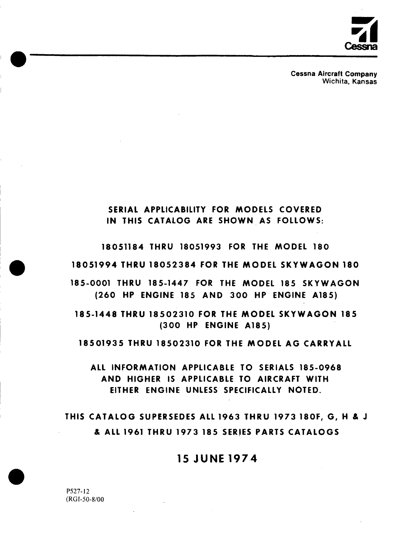
This catalog is not limited to one single production block. Its opening applicability page separates coverage by model designation and serial range, which is important when matching parts to a particular aircraft. It lists Model 180 serials 18051184 THRU 18051993, Skywagon 180 serials 18051994 THRU 18052384, 185 Skywagon serials 185-0001 THRU 185-1447, Skywagon 185 serials 185-1448 THRU 18502310, and AG Carryall serials 18501935 THRU 18502310. The opening page also identifies 260 HP ENGINE 185 and 300 HP ENGINE A185 applicability for the 185-series coverage and notes that information applicable to serials 185-0968 and higher applies to aircraft with either engine unless specifically noted.

Because many figures use lettered usable-on codes tied to serial blocks, the serial number matters throughout the catalog. The introduction explains that usable-on codes apply to the figure on which they appear and that the serials corresponding to those codes are listed at the end of the figure. This makes the catalog especially useful when the same assembly changed across production ranges or when later parts became interchangeable with earlier designs.

Chapters Covered

The catalog is organized around indexed illustrated parts figures rather than conventional service-manual chapters. Major figure groups and subjects include:

Complete PDF Bookmark Tree

Complete Bookmarks

The complete bookmarks in the “1961-1973 Cessna 180 & 185 Series Illustrated Parts Catalog P527-12 – PDF Download” are as follows:

P527-12 – MODELS 180 AND 185 (1961 THRU 1973)p. 1
TEMPORARY REVISION NUMBER 2p. 2
TEMPORARY REVISION NO. 1p. 6
LIST OF EFFECTIVE PAGESp. 7
INTRODUCTIONp. 9
STANDARD PARTSp. 9
SYMBOLS & PART NUMBER TERMSp. 9
GROUP ASSEMBLY PARTS LIST ARRANGEMENTp. 9
ACCESSORY KITSp. 10
BULK ITEMSp. 10
HOW TO ORDERp. 10
SERIAL, COLOR, & CORROSION PROOFINGp. 10
DISTRIBUTOR ORDERSp. 10
DEALER ORDERSp. 10
RETAIL ORDERSp. 10
PAINT AND UPHOLSTERY COMBINATIONSp. 11
FINISH & TRIM PLATE (1961 THRU 1965)p. 11
PAINT CODE CHART (1961 THRU 1965)p. 11
FINISH & TRIM PLATE (1966 & ON)p. 15
PAINT CODE CHART (1966 & ON)p. 16
UPHOLSTERY & INTERIOR TRIMp. 23
UPHOLSTERED PARTS – HOW TO ORDERp. 24
INTERIOR PAINTED OR PLASTIC PARTS HOW TO ORDERp. 25
INTERIOR PAINTED OR PLASTIC PARTSp. 26
INTERIOR PAINTED OR PLASTIC PARTS – 1965 MODEL YEAR ONLYp. 26
INTERIOR PAINTED OR PLASTIC PARTS – 1966 MODEL YEARp. 27
INTERIOR PAINTED OR PLASTIC PARTS – 1967 MODEL YEARp. 28
INTERIOR PAINTED OR PLASTIC PARTS – 1968 MODEL YEARp. 29
INTERIOR PAINTED OR PLASTIC PARTS – 1969 MODEL YEARp. 30
INTERIOR PAINTED OR PLASTIC PARTS – 1970 MODEL YEARp. 31
INTERIOR PAINTED OR PLASTIC PARTS – 1971 MODEL YEARp. 33
INTERIOR PAINTED OR PLASTIC PARTS – 1973 MODEL YEARp. 35
ALPHABETICAL INDEXp. 37
PARTS LISTINGp. 61
BULK ITEMSp. 62
FIGURE 1. MISCELLANEOUS BULK ITEMSp. 64
PLACARDSp. 68
FIGURE 2. (SHEET 1 OF 2) PLACARDS, NAMEPLATES & EXTERIOR MARKINGSp. 67
FIGURE 2. (SHEET 2 OF 2) PLACARDS, NAMEPLATES & EXTERIOR MARKINGSp. 69
FIGURE 2A. (SHEET 1 OF 2) PLACARDS, NAMEPLATES & EXTERIOR MARKINGSp. 71
FIGURE 2A. (SHEET 2 OF 2) PLACARDS, NAMEPLATES & EXTERIOR MARKINGSp. 72
FIGURE 2B. (SHEET 1 OF 4) PLACARDS, NAMEPLATES & EXTERIOR MARKINGSp. 75
FIGURE 2B. (SHEET 2 OF 4) PLACARDS, NAMEPLATES & EXTERIOR MARKINGSp. 76
FIGURE 2B. (SHEET 3 OF 4 ) PLACARDS, NAMEPLATES & EXTERIOR MARKINGSp. 77
FIGURE 2B. (SHEET 4 OF 4) PLACARDS, NAMEPLATES & EXTERIOR MARKINGSp. 79
FIGURE 2C. (SHEET 1 OF 2) PLACARDS, NAMEPLATES & EXTERIOR MARKINGSp. 81
FIGURE 2C. (SHEET 2 OF 2) PLACARDS, NAMEPLATES & EXTERIOR MARKINGSp. 83
WINGp. 86
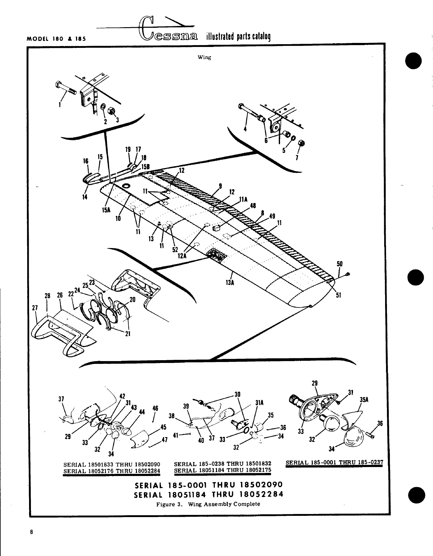
FIGURE 3. WING ASSEMBLY COMPLETEp. 85
FIGURE 3A. WING ASSEMBLY COMPLETEp. 89
FIGURE 4. WING STRUCTURE ASSEMBLYp. 92
FIGURE 5. WING STRUCTURE ASSEMBLYp. 96
FIGURE 6. WING STRUCTURE ASSEMBLY EXTENDED RANGEp. 99
FIGURE 6A. WING STRUCTURE ASSEMBLYp. 103
FIGURE 7. WING LEADING EDGE ASSEMBLYp. 106
FIGURE 8. WING LEADING EDGE ASSEMBLYp. 108
FIGURE 8A. WING LEADING EDGE ASSEMBLYp. 111
FIGURE 9. WING SPARS ASSEMBLIESp. 113
FIGURE 10. WING SPAR ASSEMBLIESp. 115
FIGURE 10A. WING SPAR ASSEMBLIESp. 118
FIGURE 11. SKINS & STRINGERS INSTALLATIONp. 120
FIGURE 12. SKINS & STRINGERS INSTALLATIONp. 122
FIGURE 12A. SKINS & STRINGERS INSTALLATIONp. 125
FIGURE 13. FUEL TANK INSTALLATIONp. 127
FIGURE 13A. FUEL TANK DRAIN VALVE INSTALLATIONp. 130
FIGURE 14. AILERON INSTALLATIONp. 132
FIGURE 15. FLAP INSTALLATIONp. 134
STRUTp. 137
FIGURE 16. STRUT INSTALLATIONp. 136
EMPENNAGEp. 139
FIGURE 17. FIN & DORSAL INSTALLATIONp. 138
FIGURE 18. FIN & DORSAL INSTALLATIONp. 140
FIGURE 19. STABILIZER INSTALLATIONp. 143
FIGURE 20. RUDDER ASSEMBLYp. 147
FIGURE 21. ELEVATOR INSTALLATIONp. 149
FUSELAGEp. 152
FIGURE 22. FUSELAGE ASSEMBLYp. 151
FIGURE 23. FUSELAGE ASSEMBLYp. 154
FIGURE 24. FUSELAGE FRONT & CENTER SECTIONp. 156
FIGURE 25. FUSELAGE FRONT & CENTER SECTIONp. 162
FIGURE 26. REAR CABIN TOP SKIN ASSEMBLYp. 164
FIGURE 27. FUSELAGE CENTER SECTION FLOORBOARDS INSTALLATIONp. 166
FIGURE 28. FUSELAGE FRONT SECTION STRUCTURE ASSEMBLYp. 167
FIGURE 29. FUSELAGE FRONT SECTION STRUCTURE ASSEMBLYp. 171
FIGURE 30. LANDING GEAR BULKHEAD ASSEMBLYp. 173
FIGURE 31. WINDSHIELD INSTALLATIONp. 177
FIGURE 32. FUSELAGE BULKHEAD ASSEMBLY STA. 65.33p. 178
FIGURE 32A. FUSELAGE BULKHEAD ASSEMBLY STA. 65.33p. 180
FIGURE 33. FIREWALL ASSEMBLYp. 183
FIGURE 34. FIREWALL GROMMETS INSTALLATIONp. 186
FIGURE 34A. FIREWALL GROMMETS INSTALLATIONp. 188
FIGURE 35. FUSELAGE AFT SECTION ASSEMBLYp. 190
FIGURE 35A. FUSELAGE AFT SECTION ASSEMBLYp. 193
FIGURE 35B. LITTER DOOR COMPONENTS INSTALLATIONp. 197
FIGURE 36. BATTERY BOX ASSEMBLYp. 199
FIGURE 37. BATTERY BOX ASSEMBLYp. 200
FIGURE 38. FUSELAGE TAILCONE ASSEMBLYp. 201
FIGURE 39. STINGER INSTALLATIONp. 203
ALIGHTING GEARp. 204
FIGURE 40. MAIN LANDING GEAR INSTALLATIONp. 205
FIGURE 40A. MAIN LANDING GEAR INSTALLATION (CROSSWIND)p. 207
FIGURE 41. LANDING GEAR INSTALLATIONp. 210
FIGURE 42. MAIN LANDING GEAR WHEEL & BRAKE ASSEMBLYp. 213
FIGURE 42A. MAIN LANDING GEAR WHEEL AND BRAKE INSTALLATIONp. 215
FIGURE 42B. MAIN LANDING GEAR WHEEL & BRAKE ASSEMBLYp. 218
FIGURE 42C. MAIN LANDING GEAR WHEEL & BRAKE ASSEMBLY-CROSSWINDp. 220
FIGURE 43. MAIN LANDING GEAR WHEEL & BRAKE ASSEMBLYp. 222
FIGURE 44. CROSSWIND WHEEL AND BRAKE ASSEMBLYp. 224
FIGURE 45. TAIL WHEEL INSTALLATIONp. 227
FIGURE 46. TAIL WHEEL INSTALLATION – ANTI-SWIVELp. 229
FIGURE 46A. TAILWHEEL INSTALLATION – ANTI-SWIVELp. 231
FIGURE 46B. TAILWHEEL & LOCK INSTALLATION – MANUALp. 234
FIGURE 47. TAILWHEEL ASSEMBLYp. 238
FIGURE 48. TAIL WEEL ASSEMBLYp. 240
FIGURE 48A. TAIL WHEEL ASSEMBLYp. 242
FIGURE 48B. TAILWHEEL ASSEMBLYp. 244
DOOR & WINDOWp. 248
FIGURE 49. LEFT CABIN DOOR INSTALLATIONp. 247
FIGURE 50. RIGHT CABIN DOOR INSTALLATIONp. 251
FIGURE 51. REMOVABLE LATCH ASSEMBLYp. 253
FIGURE 51A. CABIN DOOR LATCH ASSEMBLYp. 255
BAGGAGE DOORp. 258
FIGURE 52. BAGGAGE DOOR INSTALLATIONp. 257
UPHOLSTERYp. 260
FIGURE 53. CABIN TOP AND FIREWALL UPHOLSTERY INSTALLATIONp. 259
FIGURE 54. CABIN DOORS UPHOLSTERY INSTALLATIONp. 261
FIGURE 55. FLOORBOARD UPHOLSTERY INSTALLATIONp. 263
FIGURE 56. FLOORBOARDS UPHOLSTERY INSTALLATION (DE LUXE)p. 266
FIGURE 57. CABIN SIDE PANELS & BAGGAGE COMPARTMENT UPHOLSTERY INSTALLATIONp. 268
FIGURE 57A. CABIN SIDE PANEL & BAGGAGE COMPARTMENT UPHOLSTERY INSTALLATIONp. 272
FIGURE 58. CABIN SIDE PANELS & BAGGAGE COMPARTMENT UPHOLSTERY INSTALLATIONp. 276
SEATSp. 279
FIGURE 59. FRONT SEAT INSTALLATIONp. 278
FIGURE 59A. RECLINING FRONT SEATp. 280
FIGURE 60. FRONT SEAT INSTALLATIONp. 283
FIGURE 61. FRONT SEAT INSTALLATIONp. 287
FIGURE 61A. FRONT SEAT INSTALLATIONp. 289
FIGURE 62. ADJUSTABLE FRONT SEAT INSTALLATIONp. 292
FIGURE 63. VERTICALLY ADJUSTABLE FRONT SEATp. 296
FIGURE 63A. PILOT & CO-PILOT POWER ADJUSTABLE SEAT INSTALLATIONp. 301
FIGURE 63B. POWER SEAT BOTTOM ASSEMBLY – PILOT & CO-PILOTp. 303
FIGURE 63C. INFINITELY ADJUSTABLE FRONT SEAT INSTALLATIONp. 305
FIGURE 64. REAR SEAT INSTALLATIONp. 310
FIGURE 64A. REAR SEAT INSTALLATIONp. 313
FIGURE 65. STOWABLE REAR SEATS INSTALLATIONp. 315
FIGURE 65A. DIVIDED MIDDLE SEAT ASSEMBLYp. 318
FIGURE 65B. CHILD SEAT INSTALLATIONp. 320
FIGURE 66. AUXILLIARY SEAT INSTALLATIONp. 322
INSTRUMENTSp. 325
FIGURE 67. INSTRUMENT PANEL EQUIPMENT INSTALLATION AND ASSEMBLYp. 324
FIGURE 68. INSTRUMENT PANEL EQUIPMENT INSTALLATION & ASSEMBLYp. 330
FIGURE 68A. INSTRUMENT PANEL EQUIPMENT INSTALLATIONp. 334
FIGURE 68B. INSTRUMENT PANEL EQUIPMENT INSTALLATIONp. 340
FIGURE 68C. INSTRUMENT PANEL EQUIPMENT INSTALLATIONp. 346
FIGURE 68D. SWITCH & CIRCUIT BREAKER INSTALLATIONp. 349
FIGURE 68E. SWITCH & CIRCUIT BREAKER INSTALLATIONp. 351
FIGURE 69. GLOVE BOX & MAP CASE INSTALLATIONp. 353
FIGURE 69A. GLOVE BOX INSTALLATIONp. 356
FUSELAGE EQUIPMENTp. 358
FIGURE 70. FUSELAGE EQUIPMENT INSTALLATIONp. 357
FIGURE 70A. WIRE CUTTER & CABLE DEFLECTOR INSTALLATIONp. 360
FIGURE 70B. AUXILIARY REFUELING EQUIPMENT INSTALLATIONp. 362
PROPELLERp. 365
FIGURE 71. PROPELLER INSTALLATIONp. 364
FIGURE 72. MCCAULEY PROPELLER ASSEMBLYp. 367
FIGURE 72A. MCCAULEY PROPELLER ASSEMBLYp. 369
FIGURE 72B. MCCAULEY PROPELLER ASSEMBLYp. 373
FIGURE 72C. PROPELLER ASSEMBLYp. 375
COWLINGp. 378
FIGURE 73. ENGINE COWL INSTALLATIONp. 379
FIGURE 73A. ENGINE COWL INSTALLATIONp. 383
ENGINEp. 386
FIGURE 74. (SHEET 1 OF 2) ENGINE INSTALLATIONp. 387
FIGURE 74. (SHEET 2 OF 2) ENGINE INSTALLATIONp. 388
FIGURE 75. ENGINE INSTALLATIONp. 393
FIGURE 76. (SHEET 1 OF 2) ENGINE ASSEMBLYp. 397
FIGURE 76. (SHEET 2 OF 2) ENGINE ASSEMBLYp. 398
FIGURE 76A. ENGINE COMPONENTS & ASSOCIATED ACCESSORIESp. 402
FIGURE 77. ENGINE ASSEMBLYp. 403
FIGURE 77A. NON CONGEALING OIL COOLER INSTALLATIONp. 407
FIGURE 77B. ENGINE COMPONENTS & ASSOCIATED ACCESSORIESp. 409
FIGURE 78. INDUCTION SYSTEM AIR BOX ASSEMBLYp. 410
FIGURE 78A. INDUCTION AIR BOX ASSEMBLYp. 303
FIGURE 79. PROPELLER GOVERNOR ASSEMBLYp. 414
FIGURE 79A. PROPELLER GOVERNOR ASSEMBLYp. 416
FIGURE 80. PROPELLER GOVERNOR ASSEMBLY – HOOFp. 418
FIGURE 81. PROPELLER GOVERNOR ASSEMBLY – GARWINp. 420
FIGURE 81A. GOVERNOR ASSEMBLYp. 422
FIGURE 81B. PROPELLER GOVERNOR ASSEMBLY – GARWINp. 424
FIGURE 81C. PROPELLER GOVERNOR ASSEMBLYp. 426
FIGURE 81D. GOVERNOR ASSEMBLYp. 428
FIGURE 82. EXHAUST STACKS INSTALLATIONp. 430
FIGURE 83. ENGINE EXHAUST STACKp. 432
FIGURE 84. ENGINE BAFFLES INSTALLATIONp. 434
FIGURE 85. ENGINE BAFFLES INSTALLATIONp. 437
FIGURE 86. WINTERIZATION EQUIPMENT INSTALLATIONp. 440
COWL FLAPS CONTROL SYSTEMp. 442
FIGURE 87. COWL FLAPS CONTROL SYSTEM INSTALLATIONp. 441
FIGURE 87A. COWL FLAPS EXTENSION INSTALLATION – AGCARRYALLp. 444
VENTILATION SYSTEMp. 446
FIGURE 88. CABIN VENTILATION SYSTEM INSTALLATIONp. 445
FIGURE 88A. CABIN VENTILATION SYSTEM INSTALLATIONp. 447
HEATING SYSTEMp. 451
FIGURE 89. MANIFOLD CABIN HEATER INSTALLATIONp. 450
BRAKE SYSTEMp. 454
FIGURE 90. BRAKE SYSTEM INSTALLATIONp. 453
FLIGHT CONTROLSp. 457
FIGURE 91. RUDDER AND BRAKE PEDAL INSTALLATIONp. 456
FIGURE 92. RUDDER AND BRAKE PEDAL INSTALLATIONp. 458
FIGURE 93. BRAKE MASTER CYLINDER ASSEMBLYp. 462
FIGURE 94. CONTROL TEE INSTALLATIONp. 463
FIGURE 94A. CONTROL YOKE INSTALLATIONp. 466
FIGURE 94B. CONTROL WHEEL & SWITCHES INSTALLATIONp. 468
FIGURE 95. AILERON CONTROL SYSTEM INSTALLATIONp. 470
FIGURE 95A. WING LEVELER INSTALLATIONp. 473
FIGURE 95B. WING LEVELER COMPONENTSp. 475
FIGURE 96. ELEVATOR CONTROL SYSTEM INSTALLATIONp. 479
FIGURE 97. FLAP CONTROL SYSTEM INSTALLATIONp. 481
FIGURE 98. RUDDER CONTROL SYSTEM INSTALLATIONp. 485
FIGURE 99. RUDDER CONTROL SYSTEM INSTALLATIONp. 488
FIGURE 99A. RUDDER TRIM INSTALLATIONp. 490
FIGURE 100. STABILIZER TRIM CONTROL SYSTEM INSTALLATIONp. 492
FIGURE 100A. STABILIZER TRIM WHEEL ASSEMBLY INSTALLATIONp. 495
PITOT SYSTEMp. 496
FIGURE 101. PITOT SYSTEM INSTALLATIONp. 497
FIGURE 102. PITOT SYSTEM INSTALLATIONp. 500
FIGURE 102A. ALTERNATE STATIC SOURCE INSTALLATIONp. 504
STALL WARNINGp. 506
FIGURE 102B. STALL WARNING HORN INSTALLATIONp. 506
FUEL SYSTEMp. 507
FIGURE 103. FUEL SYSTEMp. 508
FIGURE 104. FUEL SYSTEM INSTALLATIONp. 510
FIGURE 105. FUEL SYSTEM – SELECTABLE TANKp. 514
FIGURE 106. FUEL SYSTEM INSTALLATIONp. 518
FIGURE 107. FUEL PUMP & STRAINER INSTALLATIONp. 521
FIGURE 108. AUXILIARY FUEL PUMP & STRAINER INSTALLATIONp. 523
FIGURE 109. FUEL STRAINER ASSEMBLY & DRAIN INSTALLATIONp. 525
FIGURE 110. FUEL STRAINER & DRAIN INSTALLATIONp. 527
FIGURE 110A. FUEL STRAINER & DRAIN CONTROL INSTALLATIONp. 529
FIGURE 111. FUEL VALVE ASSEMBLYp. 531
FIGURE 112. FUEL SELECTOR VALVE ASSEMBLYp. 532
OIL SYSTEMp. 534
FIGURE 113. OIL SYSTEM INSTALLATIONp. 533
FIGURE 113A. OIL FILTER INSTALLATIONp. 536
FIGURE 114. OIL SYSTEM INSTALLATIONp. 538
OIL FILTERp. 540
FIGURE 115. FULL FLOW OIL FILTER INSTALLATIONp. 540
VACUUM SYSTEMp. 541
FIGURE 116. VACUUM SYSTEM INSTALLATIONp. 542
FIGURE 117. VACUUM SYSTEM INSTALLATIONp. 544
FIGURE 117A. VACUUM SYSTEM INSTALLATIONp. 548
FIGURE 117B. VACUUM SYSTEM INSTALLATIONp. 550
FIGURE 117C. VACUUM SYSTEM INSTALLATIONp. 554
FIGURE 117D. VACUUM SYSTEM INSTALLATION-FORWARD OF FIREWALLp. 556
FIGURE 117E. VACUUM SYSTEMp. 558
FIGURE 118. FUEL PRIMER SYSTEM INSTALLATIONp. 560
FIGURE 118A. FUEL PRIMER SYSTEM INSTALLATIONp. 562
OXYGEN SYSTEMp. 565
FIGURE 119. OXYGEN SYSTEM INSTALLATIONp. 564
FIGURE 120. OXYGEN SYSTEM INSTALLATIONp. 566
FIGURE 120A. OXYGEN SYSTEM INSTALLATIONp. 568
FIGURE 120B. OXYGEN SYSTEM INSTALLATIONp. 572
FIGURE 120C. OXYGEN SYSTEM INSTALLATIONp. 574
ELECTRICAL EQUIPMENTp. 579
FIGURE 121. FUSELAGE ELECTRICAL EQUIPMENT INSTALLATIONp. 578
FIGURE 122. FUSELAGE ELECTRICAL EQUIPMENT INSTALLATIONp. 584
FIGURE 123. CABIN LIGHTS & COURTESY LIGHT INSTALLATIONp. 588
FIGURE 123A. MAP LIGHT INSTALLATIONp. 591
FIGURE 123B. SHOCK MOUNTED ALTERNATORp. 593
FIGURE 124. ROTATING BEACON INSTALLATIONp. 595
FIGURE 124A. FLASHING BEACON INSTALLATIONp. 597
FIGURE 125. GROUND SERVICE PLUG INSTALLATIONp. 599
FIGURE 125A. GROUND SERVICE PLUG INSTALLATIONp. 600
FIGURE 125B. GROUND SERVICE PLUG INSTALLATIONp. 601
FIGURE 125C. LANDING LIGHT INSTALLATION-COWLp. 602
FLOATPLANE FITTINGSp. 604
FIGURE 126. FLOATPLANE FITTINGS INSTALLATIONp. 603
FIGURE 126A. FLOATPLANE & SKI PLANE COMPONENTSp. 607
FIGURE 127. FLOATPLANE FITTINGS (EDO NO. 249-2870)p. 610
FIGURE 128. AMPHIBIAN FITTINGSp. 612
CARGO PODp. 615
FIGURE 129. CARGO POD INSTALLATIONp. 616
FIGURE 130. STRETCHER INSTALLATIONp. 618
CAMERAp. 619
FIGURE 131. CENTER-LINE CAMERA PROVISIONp. 620
FIGURE 132. CENTER-LINE CAMERA PROVISIONp. 624
FIGURE 133. OFF-CENTER CAMERA PROVISIONSp. 627
AUTOPILOTp. 630
FIGURE 135. TACTAIR T-2 AUTOPILOT INSTALLATIONp. 633
FIGURE 136. VACUUM SYSTEM FOR TACTAIR AUTO PILOTp. 637
NUMERICAL INDEXp. 639

  • Catalog identification and reference information

    • Serial applicability, temporary revisions, list of effective pages, introduction, symbols, part-number terms, usable-on codes, alphabetical index, and numerical index
    • Finish and trim plates, paint and upholstery code charts, and instructions for ordering upholstered, painted, and plastic interior parts
  • Placards, nameplates, markings, and bulk items

    • Miscellaneous bulk materials, seals, hoses, mouldings, electrical connector items, and trim
    • Placards, operational markings, exterior lettering, control-wheel insignia, fuel markings, and model-specific nameplates
  • Wing assemblies

    • Complete standard- and extended-range wing assemblies, wing structure, leading-edge assemblies, spars, skins and stringers, fuel-tank installation, ailerons, and flaps
    • Landing, navigation, and strobe-light components plus static dischargers and wing-position equipment where applicable
  • Empennage

    • Fin and dorsal installation, stabilizer-related structure, rudder, elevator, hinges, spars, ribs, tips, and associated installations
  • Fuselage structure

    • Complete fuselage assemblies, front and center sections, aft section, tailcone, firewall, bulkheads, floorboards, windshield installation, battery boxes, doors, and baggage-door components
    • Camera provisions, cargo-related fittings, and structural details identified for applicable configurations
  • Landing gear and brakes

    • Main landing gear, crosswind gear, wheel and brake assemblies, tailwheel installations, tailwheel lock and steering components, brake lines, and master-cylinder assemblies
  • Cabin, upholstery, seats, and interior equipment

    • Cabin-top and firewall upholstery, door upholstery, floorboard and baggage-compartment trim, side panels, front and rear seats, adjustable and power-seat arrangements, stowable seats, divided middle seat, child seat, and auxiliary seat installations
  • Instruments and controls

    • Instrument-panel equipment, glove box and map case, fuselage equipment, control tee and yoke, control-wheel switches, and flight-control system installations for aileron, elevator, rudder, flap, and stabilizer trim
  • Propeller and engine-related assemblies

    • Propeller installation and propeller assemblies, engine cowl, engine installation, engine assembly, induction air box, propeller governors, exhaust stacks, engine baffles, and cowl-flap controls
  • Air, brake, fuel, oil, and vacuum systems

    • Cabin ventilation and heater installations, brake system, pitot and alternate static source components, fuel systems, fuel pumps and strainers, oil system and filter installations, and vacuum system installations
  • Oxygen and electrical equipment

    • Oxygen system installations, fuselage electrical equipment, cabin and courtesy lights, map lights, alternator installations, rotating and flashing beacons, ground-service plugs, and landing-light installations
  • Special and optional installations

    • Floatplane fittings, ski-plane components, cargo pod, stretcher, center-line camera provisions, AG Carryall-related items, Tactair autopilot installations, and associated vacuum-system components where listed

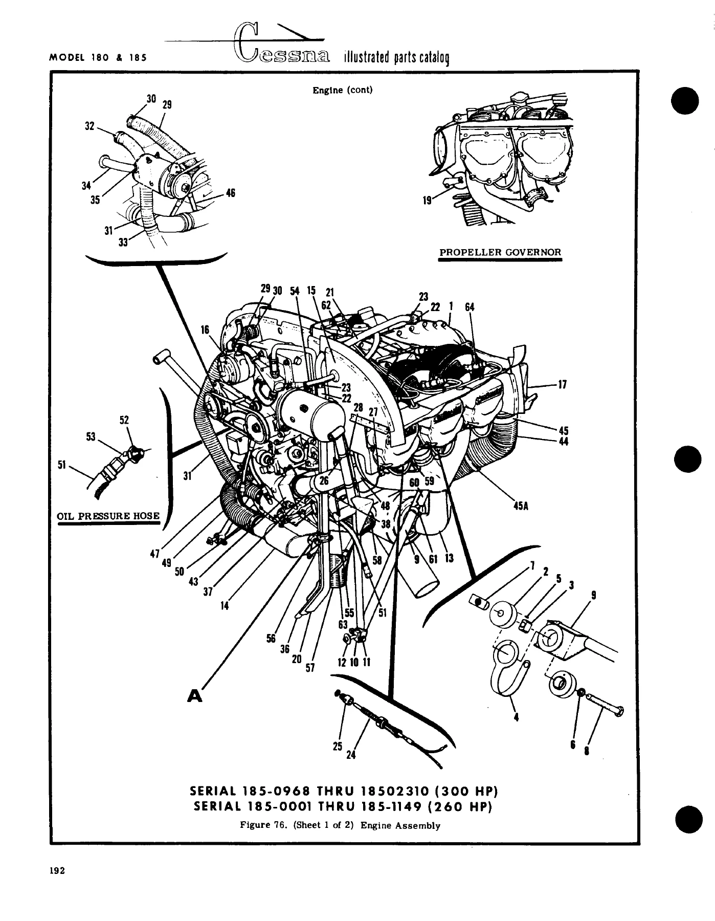
Across these groups, the illustrations are keyed to accompanying parts lists so the user can move from a drawing callout to the corresponding part number, description, quantity, and usable-on code. The catalog also provides alphabetical and numerical indexing, helping locate a component either by name or by part number. This structure is designed for parts identification and configuration matching rather than step-by-step maintenance instructions.

IMAGES PREVIEW

1961-1973 Cessna 180 & 185 Series Illustrated Parts Catalog P527-12 - PDF Download — PDF page 1 preview
1961-1973 Cessna 180 & 185 Series Illustrated Parts Catalog P527-12 - PDF Download — PDF page 85 preview
1961-1973 Cessna 180 & 185 Series Illustrated Parts Catalog P527-12 - PDF Download — PDF page 397 preview

How the Illustrated Parts Listings Help

Each illustrated figure breaks an assembly into identifiable components and links the drawing index numbers to the parts-list entries. The introduction explains the hierarchy used in the description column, including assemblies, lower assemblies, detail parts, and attaching parts. It also explains symbols such as NP for items that are not procurable and AR for quantities used as required. Standard Cessna-system parts and standard hardware references are identified with their corresponding part-number conventions.

Serial-specific usage is one of the strongest features of this Cessna 180 & 185 Series Parts Catalog. Many assemblies changed through the covered production years, and the catalog records usable-on letters and serial blocks alongside the affected listings. It also includes notes for parts that are superseded, parts to use when earlier stock is exhausted, and cases where a later design is interchangeable with an earlier design. For an owner, restorer, parts department, or technician working from an aircraft serial number, these details help narrow the correct illustrated configuration before ordering or fitting a replacement part.

The 701-page PDF also goes well beyond basic airframe panels. The figure coverage reaches fuel tanks and selectors, oil and vacuum equipment, engine and propeller installations, control systems, landing gear and braking hardware, electrical equipment, cockpit instruments, cabin trim, seating, oxygen components, lighting, and specialized installations. Paint and upholstery code charts and finish-and-trim references provide additional identification information for interior and exterior parts where color or material coding affects the full part number.

Important Reference Scope

This is an illustrated parts catalog, not a service or overhaul manual. Its purpose is parts identification, assembly breakdown, serial applicability, and configuration reference. It should therefore be used when you need to determine which components make up an assembly, locate a listed part number, understand where a component is installed, compare serial-specific configurations, or prepare parts information before maintenance or restoration work. Procedures such as detailed disassembly methods, inspection limits, torque sequences, and repair instructions are outside the primary scope of this catalog unless a specific note appears in a parts listing.

The catalog also spans multiple models, production ranges, engines, and optional installations, so a buyer should match the aircraft model and serial number to the applicable figure notes rather than assume every listed part applies to every aircraft. This serial-driven approach is visible throughout the wing, fuselage, landing gear, engine, instrument, fuel, electrical, and optional-equipment sections.

Identify the Correct Parts Before the Job Begins

The 1961-1973 Cessna 180 & 185 Series Illustrated Parts Catalog P527-12 – PDF Download gives you a structured way to identify parts and assemblies before maintenance, restoration, component replacement, or configuration work begins. Exploded illustrations, part numbers, assembly relationships, usable-on codes, and serial ranges help reduce the risk of selecting a component from the wrong production block or overlooking a superseded listing. That matters when the aircraft covered by one catalog evolved through numerous serial ranges and equipment combinations.

After purchase, the manual is delivered as an instant PDF download with no shipping wait. You can open it on compatible computers, tablets, or phones, keep it available for workshop reference, and print the pages you need for the task at hand.
Reviews

There are no reviews yet.

Be the first to review “1961-1973 Cessna 180 & 185 Series Illustrated Parts Catalog P527-12 – PDF Download”

What Our Customers Say

★★★★★ Live reviews from customers
Loading customer reviews...
0
    0
    Your Cart
    Your cart is emptyReturn to Shop
    🛒
    Recently Purchased
    🕒 verified order