
CFM56-5B A320/A321 Quick Engine Change Kit Instruction Manual (QECKIM) – Rohr Goodrich PDF
Original price was: $39.95.$24.95Current price is: $24.95.
Complete Rohr/Goodrich QECKIM for installing the CFM56-5B Quick Engine Change Kit on Airbus A320/A321. Covers QEC Kit No. 642K9001-275, S/N 43142677 OVH. 670-page PDF with full assembly sequence, torque values, and system-by-system procedures.
Description
CFM56-5B A320/A321 Quick Engine Change Kit Instruction Manual (QECKIM)
This Quick Engine Change Kit Instruction Manual (QECKIM) delivers the complete, step-by-step procedures for installing the QEC kit onto a bare CFM56-5B engine as used on Airbus A320 and A321 aircraft. Published by Rohr, Inc., a subsidiary of Goodrich Corporation operating as Goodrich Aerostructures, in May 2019, this manual is configured specifically to QEC Kit No. 642K9001-275, Serial Number 43142677 OVH. Every figure, torque value, and assembly sequence in this 670-page document is written to help technicians complete a correct, airworthy powerplant buildup.
The manual is organized under ATA 71-00-00 (Power Plant) and follows a logical assembly sequence from the demountable powerplant through engine buildup, electrical system brackets, engine mounts, and every major system installation. Each figure is represented by one or more illustrations, with index numbers cross-referenced to the parts lists and assembly tasks.
The CFM56-5B Quick Engine Change Kit Instruction Manual is a one-time-use document written to the latest serialized production configuration of the QEC Kit No. 642K9001-275. It will not be revised and is not a service maintenance document. Once the QEC kit is installed on the bare engine, technicians should refer to the CFMI Engine Shop Manual and Engine IPC for subsequent assembly, disassembly, and service work.
File Details
- Manual Type: Quick Engine Change Kit Instruction Manual (QECKIM)
- Manufacturer: Rohr, Inc. / Goodrich Aerostructures
- Engine: CFM56-5B
- Aircraft: Airbus A320 / A321
- QEC Kit No.: 642K9001-275
- QEC Kit Serial Number: S/N 43142677 OVH
- ATA Reference: 71-00-00
- Language: English
- Page Count: 670
- File Format: PDF
- Publication Date: May 2019
Chapters Covered
The manual opens with a detailed introduction covering general information, use of the manual, manual organization, abbreviations, and standard practices. The standard practices section alone covers lubrication, electrical work, electrical bonding, dissimilar metals, tubes and fittings, liquid shim, engine flange and flange hole identification, installation of fasteners, standard torque tables, equivalent parts list, and cautions, warnings, and dangers.
- Introduction — General, Use of Manual, Manual Organization, Abbreviations, Standard Practices, Equivalent Parts List, Cautions/Warnings/Dangers
- Alpha/Numeric Parts List — Complete part number index
- SDC Parts List — Source Controlled Drawing parts
- Vendor List — Supplier codes and addresses
- Consumables List — All required fluids, sealants, tapes, and chemicals
- Tool and Equipment List — RSE tools and CFMI equipment
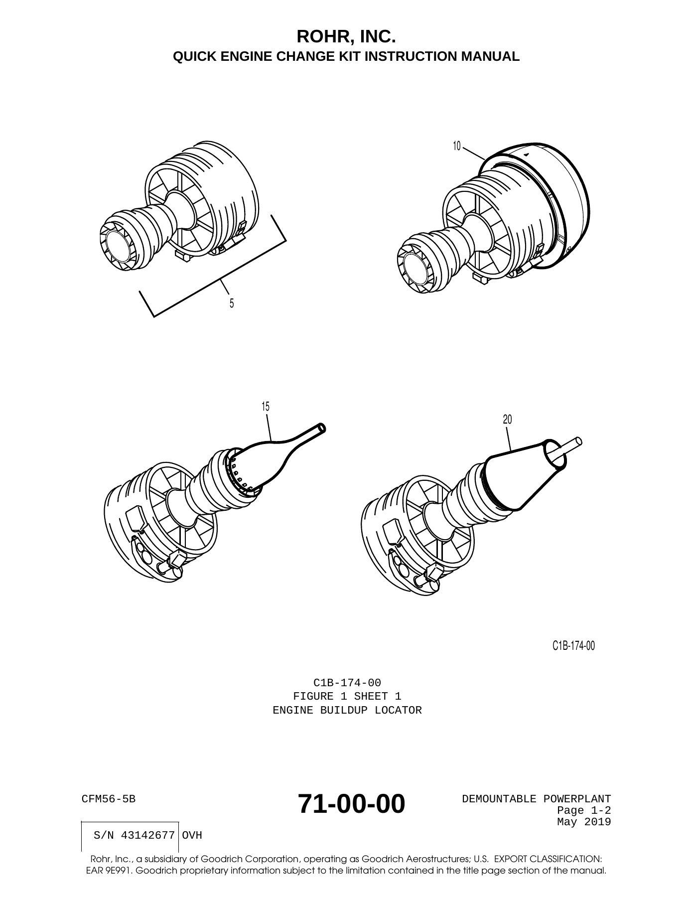
- Figure 1: Demountable Powerplant — Major assemblies and reference data
- Figure 2: Engine Buildup — Core assembly sequence
- Figure 3: Electrical System Brackets — Flange STA 158 (B1), 167 (B2), 174 (B3), 176 (B4), 185 (B5), 191 (G), 199 (A2), 215 (B8), 239 (A8), plus bridge brackets, gearbox section brackets, hot section brackets, and tube fairlead brackets
- Figure 4: Bracket Instl Split Flange — Split flange bracket references
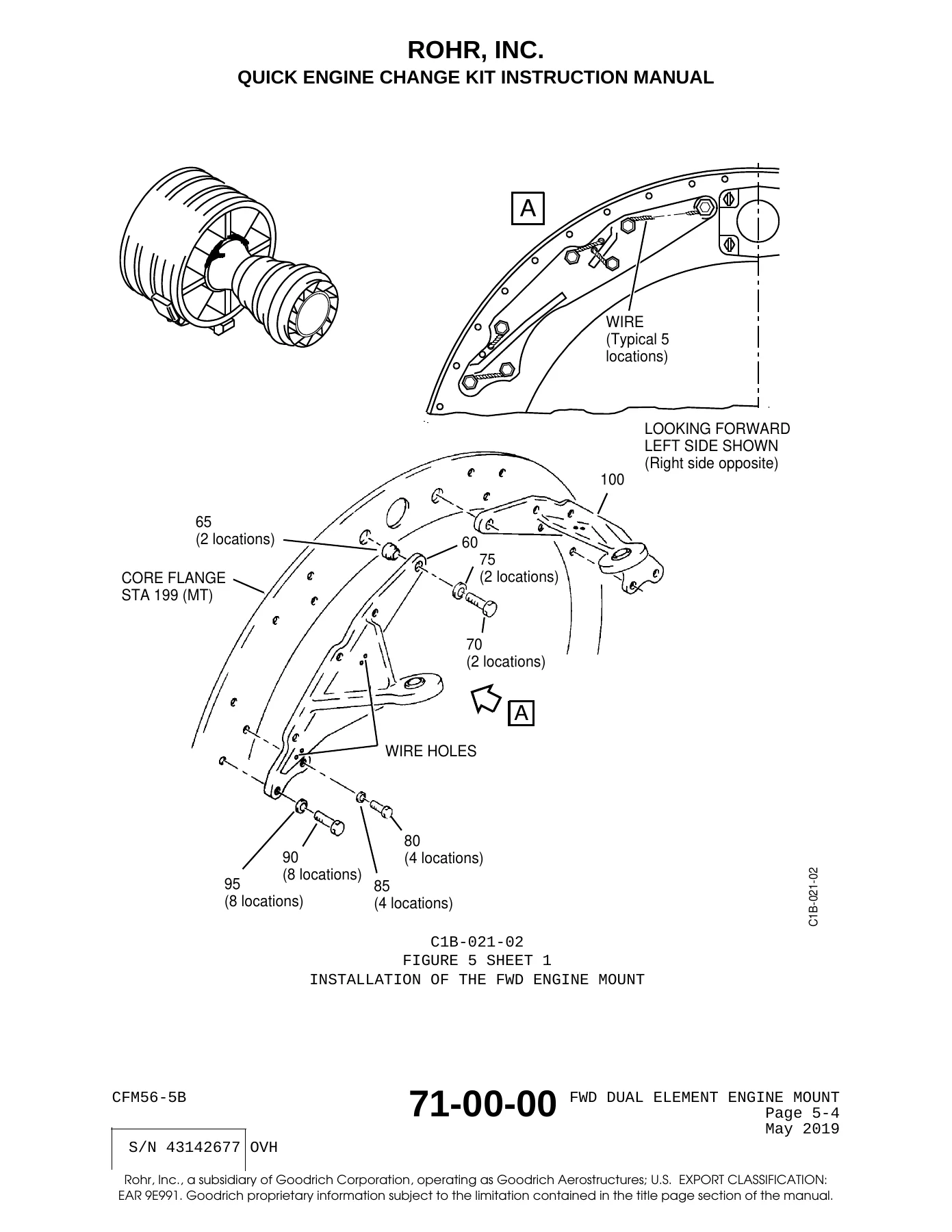
- Figure 5: Fwd Dual Element Engine Mounts — Forward engine mount installation, sealant application, and link connections
- Figure 6: Aft Engine Mount — Aft mount installation with bushings, pins, and retainers
- Figure 7: Core Section Electrical Harness — ECS valves, fire detector channels A and B, and vibration sensor harnesses
- Figure 8: Integrated Drive Generator (IDG) — QAD adapter kit, IDG installation, oil cooler hoses and tubes, and fittings
- Figure 9: Hydraulic System — Hydraulic pump fittings, pump installation, case drain filter, low pressure switch, hoses and tubes
- Figure 10: Fuel System — Differential pressure switch, fuel tubes and hoses, and fuel return bypass valve
- Figure 11: Lube Oil System — Oil pressure transmitter, low oil pressure switch, oil quantity transmitter, tubes and fittings, and oil temperature transmitter
- Figure 12: Starter System — Start duct links, upper duct, starter valve, and lower duct
- Figure 13: Drain System — Drain manifold module, reservoir module, and tubes and hoses
- Figure 14: Pneumatic System — Lower HP duct, upper HP duct, HP tee duct, upper HP duct links, 5th stage elbow, IP check valve, HP regulator valve, bleed pressure regulator valve, mid stage tee links, and HP sense tube
- Figure 15: Anti-Ice System — Fireshield, links, forward duct, anti-ice valve, middle duct, core duct, and tubes and fittings
- Figure 16: Fire Detector System — Core zone rail, fan zone rail, and fire detector connections
- Figure 17: Fan Section Electrical Harness — RH and LH side fan case line blocks, flip lock clamps, and harness routing
- Figure 18: Inlet Cowl — Inlet cowl installation with torque sequence
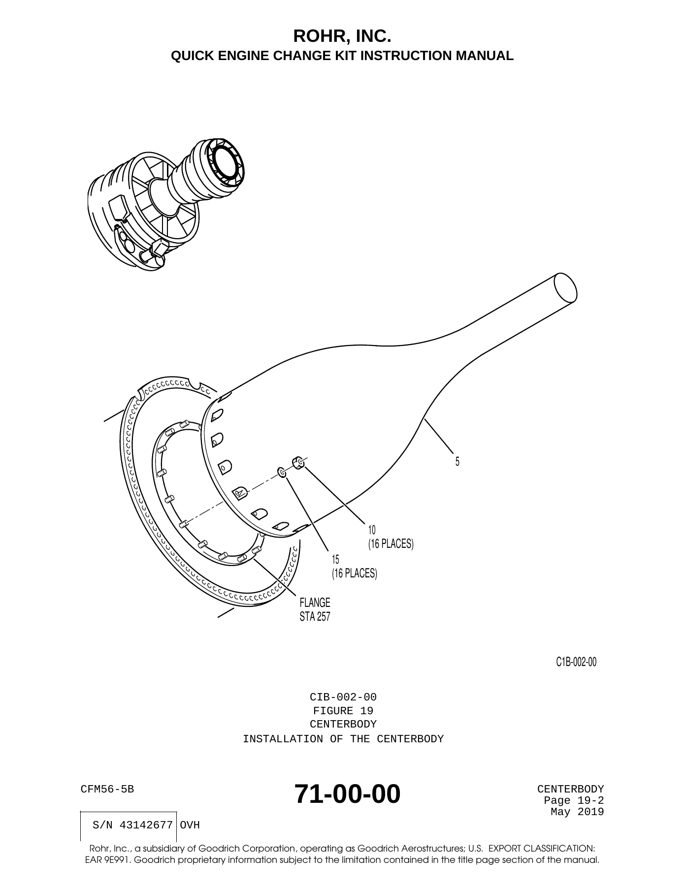
- Figure 19: Centerbody — Centerbody installation
- Figure 20: Core Nozzle — Core nozzle installation and drain tube
- Figure 21: Adapter Ring — LH and RH adapter ring segments, hold-open rods, inner flange, bottom strut, top strut, and sealant application
- Figure 22: Powerplant Equip Assy Ship-Loose — Ship-loose items for aircraft installation
- Figure 23: Additional Hdwe Kit — Not used at this time
What This Manual Enables You to Do
This QECKIM gives technicians the full assembly sequence for the CFM56-5B QEC kit, from the initial mounting of electrical system brackets on the fan case flanges through the final installation of the inlet cowl, centerbody, and core nozzle. The procedures cover every major engine system — hydraulic, fuel, lube oil, starter, drain, pneumatic, anti-ice, and fire detection — along with the integrated drive generator, forward and aft engine mounts, and the complete fan section electrical harness routing.
IMAGES PREVIEW
Each installation figure lists the required parts by index number, with tools, equipment, and consumables identified before every procedure. Torque values are given in both pound-inches and Newton-meters, and electrical resistance limits are specified where bonding is required. The manual also includes detailed safety warnings for cadmium, asbestos, beryllium, ceramic fibers, hexavalent chromium, crystalline silica, and lead, plus a complete consumables list and vendor list for sourcing materials.
Because this manual is written to the exact serialized configuration of QEC Kit S/N 43142677 OVH, the part numbers, buildup procedures, and installation sequence are specific to that kit. It is not a generic CFM56-5B manual and should not be used to install a QEC kit with a different serial number, as component part numbers and procedures may differ between kits.
Why Correct Procedures and Specifications Matter
Quick engine change kit installation demands precision. A bracket installed at the wrong flange hole, a torque value applied incorrectly, or a harness routed without the proper clearance can lead to vibration damage, chafing, electrical faults, or worse. This manual provides the exact flange hole identifications, torque sequences, electrical resistance limits, and clearance requirements that Rohr engineered for this QEC kit. Following them protects the engine, the aircraft, and the technicians performing the work.
The manual also includes important cautions about chemical exposure and proper handling of hazardous materials — critical information for anyone working with cadmium-plated fasteners, sealants, primers, and other aviation-grade chemicals.
Get Instant Access to the CFM56-5B QECKIM
This CFM56-5B A320/A321 Quick Engine Change Kit Instruction Manual is delivered as an instant PDF download after payment. No shipping, no waiting — you can access the full 670-page document on any device, print the pages you need for the shop floor, and reference the figures and procedures whenever you need them. Whether you are building up a QEC kit for the first time or need the authoritative reference for S/N 43142677 OVH, this manual gives you the complete installation sequence in one downloadable file.
Reviews
There are no reviews yet.