★ TRUSTED BY 321,897+ PROFESSIONALS WORLDWIDE
🏢
Trusted Business
Verified & Licensed
🛡️
Virus Free Files
100% Safe Downloads
🔒
Secure Payment
SSL Protected
⚡
Instant Delivery
Available Immediately
Sale!

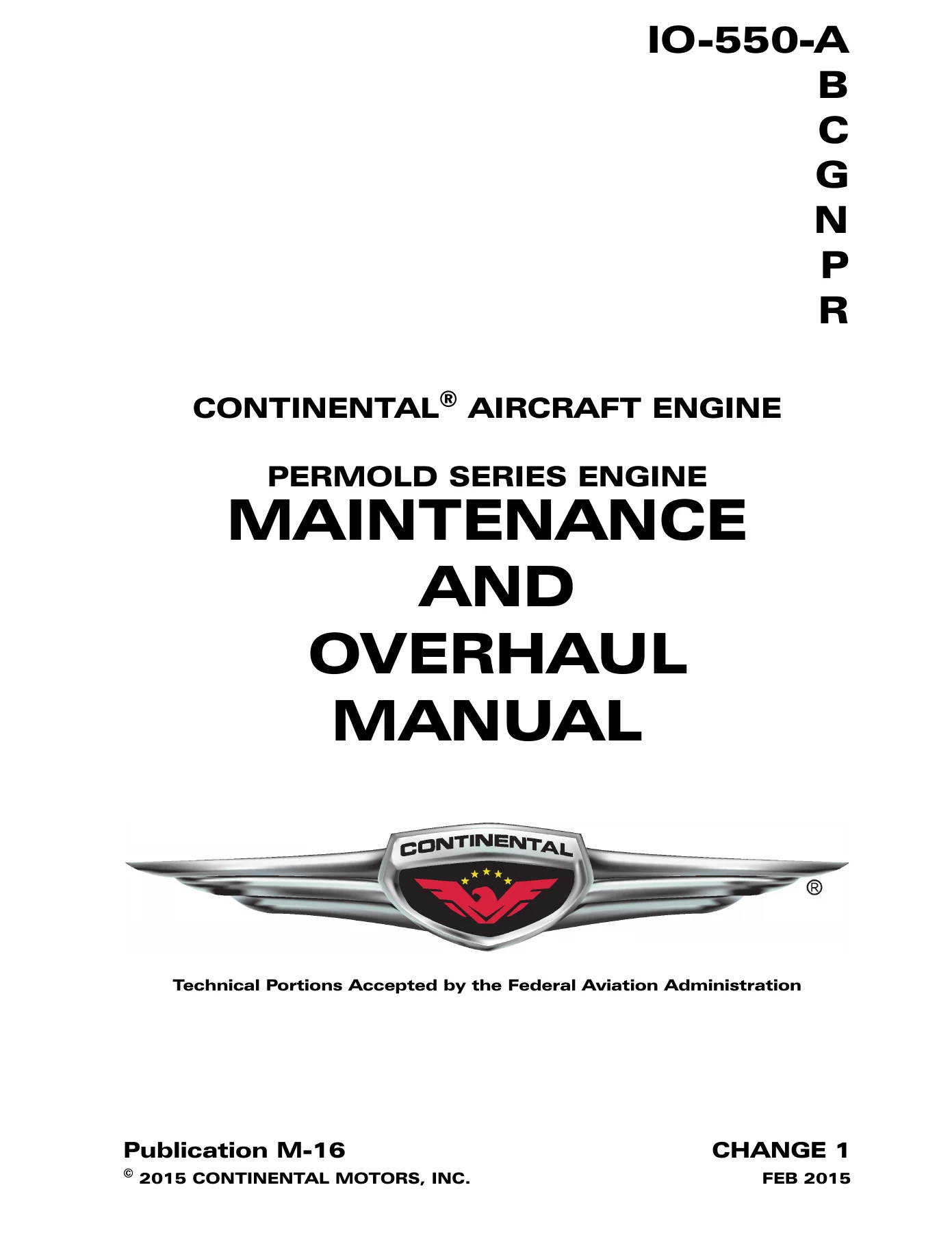
Continental IO-550 Permold Series Aircraft Engine Maintenance & Overhaul Manual M-16 PDF

Original price was: $49.95.Current price is: $29.95.

Complete 850-page Continental Motors IO-550 Permold Series Maintenance and Overhaul Manual (M-16) covering IO-550-A, B, C, G, N, P & R engines. FAA-accepted instructions for continued airworthiness with step-by-step procedures, dimensional limits, torque specs, and overhaul data.

⚡
Instant PDF Download
Available immediately
💾
Save to Your Device
Download & keep forever
🛡️
Antivirus Scanned
100% virus-free
🌍
Trusted Worldwide
175,000+ customers

Description

Continental IO-550 Permold Series Aircraft Engine Maintenance & Overhaul Manual – Document M-16

The Continental IO-550 Permold Series Aircraft Engine Maintenance & Overhaul Manual (Document M-16) is the comprehensive factory-issued service reference for all IO-550 Permold Series powerplants. This 850-page manual delivers the complete Instructions for Continued Airworthiness for the IO-550-A, IO-550-B, IO-550-C, IO-550-G, IO-550-N, IO-550-P, and IO-550-R engine models. Technical portions of this document have been accepted by the Federal Aviation Administration, and its procedures are written for FAA-licensed mechanics and certified repair station personnel.

Whether you are performing routine inspections, troubleshooting a fuel injection problem, replacing a cylinder, or completing a full engine overhaul, this manual provides the step-by-step procedures, dimensional limits, torque specifications, and service tolerances needed to keep an IO-550 Permold engine operating within its approved configuration.

File Details

  • Manual Type: Maintenance and Overhaul Manual (Instructions for Continued Airworthiness)
  • Brand / Manufacturer: Continental Motors
  • Engine Series: IO-550 Permold Series
  • Models Covered: IO-550-A, IO-550-B, IO-550-C, IO-550-G, IO-550-N, IO-550-P, IO-550-R
  • Document Number: M-16
  • Language: English
  • Page Count: 850
  • File Format: PDF

Chapters Covered

This Continental IO-550 Permold Series overhaul manual is organized into 18 chapters plus four appendices:

  • Chapter 1 – Introduction: Scope and purpose, effectivity symbols, advisories, using the manual, compliance, order of precedence, publications, service documents
  • Chapter 2 – Engine Description: General engine description, model number definition, cylinder number designations, crankcase, engine drive train, crankshaft, connecting rods, camshaft, idler gear, cylinders (updraft and crossflow), pistons, hydraulic valve tappets, lubrication system, fuel system, starter assembly, alternator, ignition system, engine cooling, induction system, exhaust system, engine specifications for each model, performance data
  • Chapter 3 – Special Tools and Supplies: Special tools list, vendor contact information, mechanic’s tools, lubricants, sealants and adhesives, engine oil specifications, oil change intervals, additives
  • Chapter 4 – Airworthiness Limitations: Mandatory replacement times, mandatory inspection intervals, other related procedures, distribution of changes
  • Chapter 5 – Engine Removal and Installation: Engine removal, engine installation, materials required, engine receipt and handling, uncrating, crating for shipping, acceptance inspection, engine transport, installation procedures, pre-oiling methods, fuel injection system purge, installation inspection, preflight and run-up, engine installation drawings for all models
  • Chapter 6 – Engine Inspection and Service: Inspection program, maintenance schedule, scheduled inspections (post-installation, 25-hour, 50-hour, 100-hour/annual, 500-hour), visual inspection, engine operational check, engine operating limits, maintenance preflight inspection, oil pump operational check, fuel system operational check, magneto RPM drop check, engine shutdown, engine oil servicing, oil change, oil leaks, oil sample collection, oil trend monitoring, ignition system maintenance, magneto timing, spark plug maintenance, ignition harness maintenance, engine adjustments, oil pressure adjustment, fuel system adjustment, auto-leaning schedule adjustments, belt tension check and adjustment, cylinder inspections, differential pressure test, borescope inspection, crankcase inspection, engine mount inspection, induction system inspection, ignition system inspection, engine gauge inspection, fuel system inspection, engine control linkage inspection, induction drain inspection, exhaust system inspection, alternator inspection, unscheduled maintenance (propeller strike, hydraulic lock, overspeed, lightning strike, contaminated fuel, foreign object contamination), inspection checklists
  • Chapter 7 – Engine Operation: Flight prerequisites, oil change interval, fuel requirements, flight check and break-in, normal operation, engine start (cold, flooded, hot), ground run-up, engine shutdown, operation in abnormal environments (extreme cold, hot weather, high density altitude)
  • Chapter 8 – Troubleshooting: General troubleshooting, engine runs rough, engine will not run, indication malfunctions, performance malfunctions, induction system, fuel injection system, charging system, starting system, ignition system, lubrication system, engine cylinders, crankcase, excess crankcase pressure, exhaust system
  • Chapter 9 – Engine Preservation and Storage: Preservation checklist, new or unused engine storage, temporary storage, indefinite storage, return to service after storage
  • Chapter 10 – Non-Overhaul Repair and Replacement: Parts replacement, fuel pump replacement, fuel injector replacement, starter motor and adapter replacement, alternator replacement, magneto replacement, lubrication system repair, oil filter adapter stud, oil pump, oil sump and suction tube, oil cooler, oil pressure relief valve, oil temperature control valve, engine cylinder maintenance (rocker arm removal, hydraulic tappet removal, cylinder removal, dimensional inspection, cylinder installation, torque, tappet installation, rocker arm installation), crankshaft nose oil seal replacement, crankcase repair, exhaust system repairs, engine preservation and storage
  • Chapter 11 – Engine Overhaul Introduction: Engine overhaul, overhaul schedule, overhaul sequence, overhaul checklists
  • Chapter 12 – Engine Disassembly: Disassembly sequence, ignition system removal, accessory drive adapter removal, fuel injection system removal, induction system removal, exhaust system removal, oil cooler removal, oil pump removal, alternator removal, compressor mounting assembly removal, starter and adapter removal, oil sump removal, engine cylinder removal, engine mount removal
  • Chapter 13 – Component Disassembly: Ignition system, fuel injection system, oil pump disassembly (standard, mechanical tachometer drive, electrical tachometer drive), starter and adapter disassembly, engine cylinder disassembly, accessory drive pad disassembly, crankcase disassembly, engine drive train disassembly (camshaft, crankshaft), compressor mounting kit disassembly
  • Chapter 14 – Engine Cleaning: Engine and component cleaning, cylinder cleaning, piston cleaning, exhaust parts cleaning, aluminum alloy parts cleaning, dry blasting, vapor blasting, protective coatings (Alodine, aviation oil, paint)
  • Chapter 15 – Overhaul Inspection and Repair: Engine overhaul inspection, checklists, visual inspection, gear tooth inspection, fluorescent penetrant inspection, magnetic particle inspection, connecting rod inspection, ultrasonic inspections, dimensional inspection (crankcase, drive train, connecting rod, crankshaft counterweight, engine cylinder, starter adapter, lubrication system, alternator drive hub, throttle and mixture control lever, exhaust system, accessory drive adapter, stud height, refrigerant compressor), overhaul repair (fuel injection system, induction system, refrigerant compressor mount, alternator, starter and adapter, ignition system, accessory drive adapter, exhaust system, lubrication system, engine cylinder, inter-cylinder baffle, crankcase, engine drive train)
  • Chapter 16 – Component Assembly: Fuel injection system assembly, alternator assembly, starter and starter adapter assembly (with scavenge pump, basic), exhaust system assembly, lubrication system assembly (oil pump, oil cooler), engine cylinder assembly, crankcase assembly, engine mount installation, engine drive train assembly (camshaft, crankshaft, connecting rod and bearing, crankshaft nose oil seal), compressor mounting kit assembly
  • Chapter 17 – Engine Assembly: Assembly sequence, component lubrication, crankcase assembly, drive train installation, crankcase hardware installation, cylinder installation, cylinder and crankcase torque, crankcase miscellaneous hardware, hydraulic valve tappet and pushrod installation, rocker arm installation, inter-cylinder baffle installation, oil sump and suction tube installation, oil pump installation, accessory drive pad installation, starter and starter adapter installation, alternator installation, oil cooler installation, induction system installation, fuel injection system installation, ignition system installation, compressor mount installation
  • Chapter 18 – Post-Overhaul Test and Adjustments: Introduction, testing prerequisites, operating limits, standard acceptance test, oil consumption test, drive belt tension check
  • Appendix A – Glossary: Acronyms, terms and definitions
  • Appendix B – Torque Specifications: General information, torque tips, cylinder torque procedure, torque wrench and extension calculations, torque tables
  • Appendix C – Standard Practices: Handling parts, replacement parts, torque, safety wiring, tab washer installation, helical coil insert replacement, stud replacement, cotter pin installation, fuel system service, Gasket Maker application, gasket installation, hose and tubing installation, harness routing
  • Appendix D – Overhaul Dimensional Limits: Fuel injection system, throttle and mixture control lever, starter and starter adapter, ignition system, lubrication system, engine cylinder, crankcase, engine drive train, crankshaft counterweight, connecting rod, stud height settings

Complete PDF Bookmark Tree

Complete Bookmarks

The complete bookmarks in the “Continental IO-550 Permold Series Aircraft Engine Maintenance & Overhaul Manual M-16 PDF” are as follows:

Chapter 1 . Introductionp. 31
1-1. Scope and Purpose of This Manualp. 31
1-1.1. Instructions for Continued Airworthinessp. 31
1-1.2. Effectivity Symbolsp. 31
1-1.3. Advisoriesp. 32
1-1.4. Using this Manualp. 32
Figure 1-1. Figure and Index Referencep. 33
1-1.5. Compliancep. 34
1-1.6. Order of Precedencep. 35
1-2. Publicationsp. 35
1-2.1. Publication Accessp. 35
1-2.2. Publication Changesp. 35
1-2.3. Update/Change Distributionp. 36
Figure 1-2. Change Page Identificationp. 36
Figure 1-3. List of Effective Pagesp. 37
1-2.4. Service Documentsp. 38
1-2.4.1. Service Documents Incorporated in this Manualp. 39
1-2.4.2. Service Documents Released after Publicationp. 42
1-2.5. Related Publicationsp. 44
Table 1-1. Related Publicationsp. 44
1-2.5.1. Suggestions and Correctionsp. 44
1-3. Contact Informationp. 45
Chapter 2 . Engine Descriptionp. 47
2-1. General Engine Descriptionp. 47
2-1.1. Engine Model Number Definitionp. 48
Figure 2-1. Engine Model Definitionp. 48
2-1.2. Cylinder Number Designationsp. 48
Figure 2-2. Cylinder Number Designationp. 48
2-2. Detailed Engine Descriptionp. 49
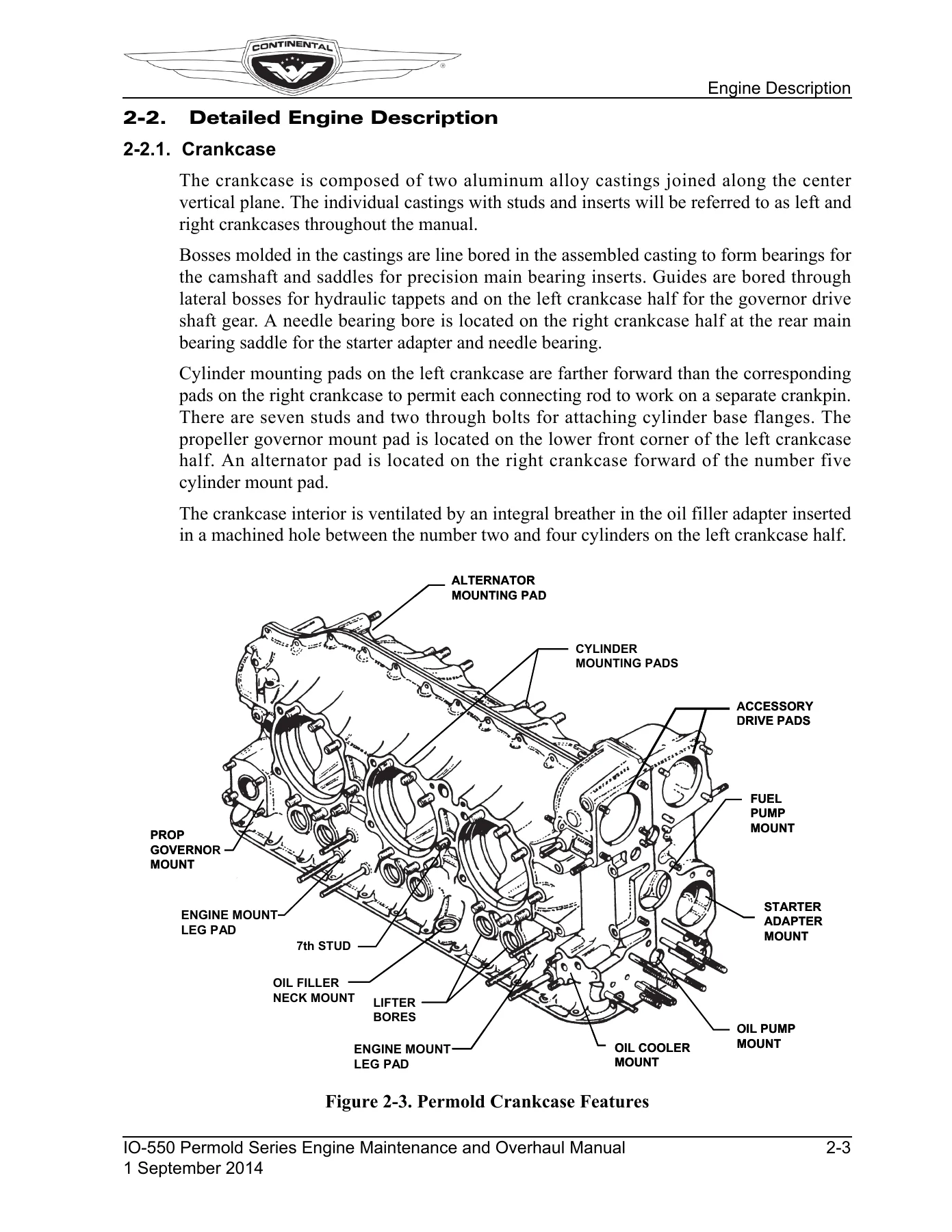
2-2.1. Crankcasep. 49
Figure 2-3. Permold Crankcase Featuresp. 49
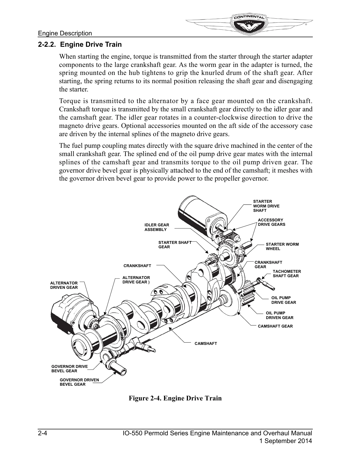
2-2.2. Engine Drive Trainp. 50
Figure 2-4. Engine Drive Trainp. 50
2-2.2.1. Crankshaftp. 51
Figure 2-5. Crankshaftp. 51
2-2.2.2. Connecting Rodsp. 51
Figure 2-6. Connecting Rodp. 52
2-2.2.3. Camshaftp. 52
Figure 2-7. Camshaftp. 52
2-2.2.4. Idler Gearp. 53
2-2.3. Cylindersp. 53
2-2.3.1. Updraft Cylinder Designp. 53
2-2.3.2. Cross-flow Cylinder Designp. 53
Figure 2-8. Updraft Cylinder Featuresp. 54
Figure 2-9. Crossflow Cylinder Featuresp. 54
2-2.3.3. Pistonsp. 55
Figure 2-10. Piston Featuresp. 55
2-2.3.4. Hydraulic Valve Tappetsp. 55
2-2.4. Lubrication Systemp. 55
Figure 2-11. Lubrication Schematicp. 56
2-2.4.1. Oil Pumpp. 56
Figure 2-12. Oil Pumpp. 57
2-2.4.2. Oil Sumpsp. 57
2-2.4.3. Oil Cooler and Oil Temperature Control Valvep. 58
Figure 2-13. Oil Coolerp. 58
2-2.5. Fuel Systemp. 59
Figure 2-14. IO-550-G, N, P & R Fuel System Schematicp. 59
Figure 2-15. IO-550-A, B & C Fuel System Schematicp. 59
2-2.5.1. Fuel Pumpp. 60
Table 2-1. Legend for Figure 2-16p. 60
Figure 2-16. IO-550 Fuel Pump Fittings and Adjustmentsp. 61
2-2.5.2. Fuel Injectorsp. 62
Figure 2-17. IO-550-A, B & C Fuel Injector Nozzlep. 62
Figure 2-18. IO-550-G, N, P & R Fuel Injector Nozzlep. 62
2-2.6. Starter Assemblyp. 63
Figure 2-19. Starting Systemp. 63
2-2.7. Alternatorp. 63
2-2.8. Ignition Systemp. 64
Figure 2-20. Continental Motors Magneto Part Number Definitionp. 64
Figure 2-21. Continental Motors Ignition System Schematicp. 65
Figure 2-22. Champion Slick Ignition System Schematicp. 65
2-2.9. Engine Coolingp. 66
Figure 2-23. Engine Coolingp. 66
2-2.10. Induction Systemp. 66
Figure 2-24. Typical Updraft Induction Systemp. 67
Figure 2-25. Typical Cross-flow Induction Systemp. 67
2-2.11. Exhaust Systemp. 68
2-3. Engine Specificationsp. 68
2-3.1. IO-550-A Specificationsp. 68
Table 2-2. IO-550-A Specificationsp. 68
2-3.2. IO-550-B Specificationsp. 70
Table 2-3. IO-550-B Specificationsp. 70
2-3.3. IO-550-C Specificationsp. 72
Table 2-4. IO-550-C Specificationsp. 72
2-3.4. IO-550-G Specificationsp. 74
Table 2-5. IO-550-G Specificationsp. 74
2-3.5. IO-550-N Specificationsp. 76
Table 2-6. IO-550-N Specificationsp. 76
2-3.6. IO-550-P Specificationsp. 78
Table 2-7. IO-550-P Specificationsp. 78
2-3.7. IO-550-R Specificationsp. 80
Table 2-8. IO-550-R Specificationsp. 80
2-3.8. IO-550-Accessory Drive Ratiosp. 82
Table 2-9. Accessory Drive Ratiosp. 82
2-3.8.1. Accessory Drive Padp. 82
2-3.9. Oil Specificationsp. 82
2-3.10. Performance Datap. 83
2-3.10.1. IO-550-A Performance Chartsp. 84
Figure 2-26. IO-550-A Fuel Flow vs. Brake Horsepowerp. 84
Figure 2-27. IO-550-A Sea Level Performancep. 85
2-3.10.2. IO-550-B Performance Chartsp. 86
Figure 2-28. IO-550-B Fuel Flow vs. Brake Horsepowerp. 86
Figure 2-29. IO-550-B Sea Level Performancep. 87
2-3.10.3. IO-550-C Performance Chartsp. 88
Figure 2-30. IO-550-C Fuel Flow vs. Brake Horsepowerp. 88
Figure 2-31. IO-550-C Sea Level Performancep. 89
2-3.10.4. IO-550-G Performance Chartsp. 90
Figure 2-32. IO-550-G Fuel Flow vs. Brake Horsepowerp. 90
Figure 2-33. IO-550-G Sea Level Performancep. 91
2-3.10.5. IO-550-N, P & R Performance Chartsp. 92
Figure 2-34. IO-550-N, P & R Fuel Flow vs. Brake Horsepowerp. 92
Figure 2-35. IO-550-N, P & R Sea Level Performancep. 93
Chapter 3 . Special Tools and Suppliesp. 95
3-1. Special Toolsp. 95
Table 3-1. Special Tools Listp. 95
3-1.1. Vendor Contact Informationp. 101
Table 3-2. Tool, Accessory and Supply Vendorsp. 101
Figure 3-1. Model E2M Differential Pressure Tester (built in Master Orifice Tool)p. 103
Figure 3-2. Borescope (Autoscope®)p. 103
Figure 3-3. Pulley Alignment Toolp. 104
Figure 3-4. Model 20 ATM-C Porta-Test Unitp. 104
Figure 3-5. Alternator Drive Hub Torque Toolp. 105
Figure 3-6. Worm Shaft Tool and Starter Adapter Disassembly Toolp. 106
Figure 3-7. Oil Control Plug Installation Toolp. 106
Figure 3-8. Oil Control Plug Leak Test Fixturep. 107
Figure 3-9. Needle Bearing Installation Tool -Part 1p. 108
Figure 3-10. Needle Bearing Installation Tool -Part 2p. 109
Figure 3-11. Bearing Installation Toolp. 110
Figure 3-12. Crankcase Needle Bearing Installation Toolp. 110
Figure 3-13. Valve Guide Seal Installation Toolp. 111
Figure 3-14. O-Ring Installation Toolp. 111
Figure 3-15. Oil Seal Toolp. 112
Figure 3-16. Helical Coil Extraction Toolp. 112
Figure 3-17. Helical Coil Insertion Toolp. 113
Figure 3-18. Helical Coil Expanding Toolp. 113
Figure 3-19. Rosan® Stud Removal Toolp. 114
Figure 3-20. Rosan Stud Removal Tool Installed on Studp. 114
3-1.2. Mechanic’s Toolsp. 115
3-2. Lubricants, Sealants and Adhesivesp. 116
3-2.1. Engine Oil Specificationsp. 116
Table 3-3. Qualified SAE J-1899 Ashless Dispersant Engine Oilp. 117
Table 3-4. Break-in Oilp. 117
Table 3-5. Preservative Oilp. 117
3-2.2. Oil Change Intervalsp. 118
3-2.3. Additivesp. 118
Table 3-6. Lubricantsp. 119
Table 3-7. Sealantsp. 120
Table 3-8. Adhesivesp. 121
Table 3-9. Miscellaneousp. 122
Chapter 4 . Airworthiness Limitationsp. 123
4-1. Mandatory Replacement Timesp. 123
4-2. Mandatory Inspection Intervalsp. 123
4-3. Other Related Proceduresp. 123
4-4. Distribution of Changes to Airworthiness Limitationsp. 123
Chapter 5 . Engine Removal and Installationp. 125
5-1. Engine Removalp. 125
5-2. Engine Installationp. 127
5-2.1. Materials Requiredp. 127
5-2.2. Engine Receipt and Handlingp. 127
5-2.2.1. Uncrating the Enginep. 128
5-2.2.2. Crating an Engine for Shippingp. 128
5-2.2.3. Acceptance Inspectionp. 128
5-2.2.4. Engine Transportp. 129
5-3. Installation Proceduresp. 130
5-3.1. Prepare the Airframe for Engine Installationp. 130
5-3.2. Prepare the Engine for Installationp. 130
5-3.3. Installation Sequencep. 132
5-3.4. Engine Pre-oilingp. 133
5-3.4.1. Pre-oiling Method 1p. 133
5-3.4.2. Pre-oiling Method 2p. 134
5-3.5. Fuel Injection System Purgep. 134
5-3.6. Installation Inspectionp. 135
5-3.7. Preflight and Run-upp. 136
5-4. Engine Installation Drawingsp. 137
5-4.1. IO-550 Common Installation Drawingsp. 137
Figure 5-1. Exhaust Port Dimensionsp. 137
Figure 5-2. Propeller Flange Dimensionsp. 138
Figure 5-3. Gear Driven Alternator Detailp. 139
Figure 5-4. Gear Driven Alternator Detail, cont.p. 140
Figure 5-5. Belt Driven Alternator Detailp. 140
5-4.2. IO-550-A Installation Drawingsp. 141
Figure 5-6. IO-550-A Front & Rear Viewp. 141
Figure 5-7. IO-550-A Top & Side Viewp. 142
5-4.3. IO-550-B Installation Drawingsp. 143
Figure 5-8. IO-550-B Front & Rear Viewp. 143
Figure 5-9. IO-550-B Top & Side Viewp. 144
5-4.4. IO-550-C Installation Drawingsp. 145
Figure 5-10. IO-550-C Front & Rear Viewp. 145
Figure 5-11. IO-550-C Top & Side Viewp. 146
5-4.5. IO-550-G & N Installation Drawingsp. 147
Figure 5-12. IO-550-G & N Front & Rear Viewp. 147
Figure 5-13. IO-550-G & N Top & Side Viewp. 148
5-4.6. IO-550-P Installation Drawingsp. 149
Figure 5-14. IO-550-P Front & Rear Viewp. 149
Figure 5-15. IO-550-P Top & Side Viewp. 150
5-4.7. IO-550-R Installation Drawingsp. 151
Figure 5-16. IO-550-R Front & Rear Viewp. 151
Figure 5-17. IO-550-R Top & Side Viewp. 152
Chapter 6 . Engine Inspection and Servicep. 153
6-1. Inspection Program Introductionp. 153
6-2. Inspection and Maintenance Schedulep. 153
6-3. Scheduled Inspectionsp. 153
Table 6-1. Engine Inspection and Maintenance Schedulep. 154
6-3.1. One Time Post – Installation Inspectionsp. 155
6-3.2. 25-Hour Initial Operation Inspectionp. 155
6-3.3. 50-Hour Engine Inspectionp. 157
6-3.4. 100-Hour (Annual) Engine Inspectionp. 158
6-3.5. 500-Hour Engine Inspectionp. 159
6-3.6. Visual Inspectionp. 160
6-3.7. Engine Operational Checkp. 162
Table 6-2. Engine Operation Prerequisitesp. 162
6-3.7.1. Engine Operating Limitsp. 163
Table 6-3. IO-550 Engine Operating Limitsp. 163
6-3.7.2. Maintenance Preflight Inspectionp. 164
6-3.7.3. Oil Pump Operational Checkp. 166
6-3.7.4. Fuel System Operational Checkp. 166
Table 6-4. Static Ground Setup Compensation Tablep. 167
6-3.7.4.1. Fuel System Operational Checkout with the Port-Test Unitp. 168
Figure 6-1. Porta-Test Connections to Integral Throttle Body/Metering Unitp. 169
Figure 6-2. Porta-Test Connections to Fuel Control Unitp. 169
6-3.7.4.2. Fuel System Operational Checkout with Calibrated Gaugesp. 170
Figure 6-3. Calibrated Gauge Connections to Integral Throttle Body/Metering Unitp. 171
Figure 6-4. Calibrated Gauge Connections to Fuel Control Unitp. 171
6-3.7.4.3. Fuel System Operational Checkout Procedurep. 172
Figure 6-5. IO-550-A, B & C Throttle Body Adjustmentsp. 173
Figure 6-6. IO-550-G, N, P & R Throttle Body Adjustmentsp. 173
Table 6-5. IO-550 Fuel Injection System Pressuresp. 174
6-3.7.5. Magneto RPM Drop Checkp. 175
6-3.7.6. Engine Shutdownp. 176
6-3.8. Engine Oil Servicingp. 177
6-3.8.1. Check and Replenish Engine Oil Levelp. 177
Figure 6-7. IO-550-A, B & C Oil Servicing Pointsp. 178
Figure 6-8. IO-550-G & N Oil Servicing Pointsp. 179
Figure 6-9. IO-550-P Oil Servicing Pointsp. 180
Figure 6-10. IO-550-R Oil Servicing Pointsp. 181
6-3.8.2. Oil Changep. 182
6-3.8.3. Check for Oil Leaksp. 183
6-3.8.4. Oil Sample Collectionp. 183
6-3.8.5. Oil Trend Monitoring and Spectrographic Oil Analysisp. 184
6-3.9. Ignition System Maintenancep. 184
6-3.9.1. Magneto Timingp. 184
6-3.9.1.1. Crankshaft Top Dead Center Alignmentp. 185
Figure 6-11. Timing Disk and TDC Locator Installedp. 185
Figure 6-12. No. 1 Cylinder Positioned at Top of Intake Strokep. 186
Figure 6-13. Crankshaft Positioned at TDCp. 186
Figure 6-14. Cylinder No. 1 Top of Compression Strokep. 187
Figure 6-15. No. 1 Cylinder Full Advance Firing Positionp. 187
6-3.9.1.2. Magneto to Engine Timingp. 188
6-3.9.2. Spark Plug Maintenancep. 189
Figure 6-16. Spark Plug Inspection Criteriap. 189
Table 6-6. IO-550 Approved Spark Plug Listp. 190
Figure 6-17. Spark Plug Rotation Chartp. 190
6-3.9.3. Ignition Harness Maintenancep. 191
Figure 6-18. Lubricate Ignition Wire with MS-122ADp. 191
Figure 6-19. Champion (Slick) Ignition Harness Routingp. 192
Figure 6-20. Continental Motors Ignition Harness Routingp. 193
6-3.10. Engine Adjustmentsp. 194
6-3.10.1. Oil Pressure Adjustmentp. 195
Figure 6-21. Oil Pressure Relief Valve Adjustment Screwp. 195
6-3.10.2. Fuel System Adjustmentp. 196
Figure 6-22. Fuel Pump Adjustmentsp. 196
6-3.10.3. Auto Leaning Schedule Adjustmentsp. 200
6-3.10.4. Belt Tension Check and Adjustmentp. 202
6-3.10.4.1. Refrigerant Compressor Drive Belt Tension Check and Adjustmentp. 202
Figure 6-23. Refrigerant Compressor Belt Tensioningp. 202
6-3.10.4.2. 70 Amp Alternator Drive Belt Tension Check and Adjustmentp. 203
Figure 6-24. 70 Amp Alternator Belt Tensioningp. 203
6-3.10.4.3. 85 Amp Alternator Drive Belt Tension Check and Adjustmentp. 204
Figure 6-25. 85 Amp Alternator Belt Tensioningp. 204
6-3.11. Cylinder Inspectionsp. 205
Table 6-7. Cylinder Inspection Tasks and Referencesp. 205
6-3.11.1. Cylinder Visual Inspectionsp. 206
Figure 6-26. Cylinder Power Stroke Areasp. 207
6-3.11.2. Differential Pressure Testp. 208
6-3.11.2.1. Differential Pressure Tester E2M Setupp. 210
Figure 6-27. Model E2M Differential Pressure Testerp. 211
6-3.11.2.2. Differential Pressure Tester Reliability Checkp. 211
6-3.11.2.3. Cylinder Differential Pressure Testp. 211
Figure 6-28. Differential Pressure Test Equipment Usagep. 212
Table 6-8. Differential Pressure Test Resultsp. 214
6-3.11.3. Cylinder Borescope Inspectionp. 216
Table 6-9. Borescope Inspection Objectives and Corrective Actionsp. 217
Figure 6-29. Normal Combustion Chamberp. 218
Figure 6-30. Burned Exhaust Valvep. 218
Figure 6-31. Phosphate-Coated Cylinder w/ Revised Hone Patternp. 218
Figure 6-32. Phosphated Cylinder Borep. 218
Figure 6-33. Cylinder Barrel Scoring and Piston Rubp. 219
Figure 6-34. Typical Wear in Upper Ring Travelp. 219
Figure 6-35. Typical Cylinder Wearp. 219
6-3.11.4. Cylinder to Crankcase Mounting Deck Inspectionp. 220
6-3.11.5. Baffle Inspectionp. 221
Figure 6-36. Improperly Positioned Baffle Sealsp. 221
Figure 6-37. Improperly Positioned Baffle Sealsp. 222
Figure 6-38. Improperly Positioned Aft and Side Peripheral Baffle Sealsp. 222
Figure 6-39. Improperly Positioned Aft and Side Peripheral Baffle Sealsp. 223
Figure 6-40. Aft and Side Baffles with Air Gapsp. 223
Figure 6-41. Cooling Loss Due to Gaps in Baffle Sealsp. 224
Figure 6-42. Cooling Loss Due to Gaps in Baffle Sealsp. 224
6-3.11.6. Cowling Inspectionp. 225
6-3.12. Crankcase Inspectionp. 226
Figure 6-43. Crankcase Critical (white) and Non-critical (Shaded) Areap. 227
6-3.12.1. Crankcase Inspection with Refrigerant Compressorp. 227
Figure 6-44. Mount Boss with Thick Ribp. 228
Figure 6-45. Mount Boss with Thin Ribp. 228
Figure 6-46. General Inspection Areap. 228
Figure 6-47. Suspect Crack Indicationp. 229
6-3.13. Engine Mount Inspectionp. 230
6-3.14. Induction System Inspectionp. 230
Figure 6-48. Induction Tube Bead Locationp. 231
Figure 6-49. Properly Installed Induction Tube, Hose and Clampsp. 231
6-3.15. Ignition System Inspectionp. 232
6-3.15.1. Impulse Coupling Functional Checkp. 233
6-3.15.2. Starting Vibrator Functional Checkp. 234
6-3.15.3. Magneto Drive Coupling Inspectionp. 235
6-3.16. Engine Gauge Inspectionp. 235
6-3.17. Fuel System Inspectionp. 236
6-3.18. Engine Control Linkage Inspectionp. 238
Figure 6-50. IO550-A, B & C Throttle Control Linkagep. 239
Figure 6-51. IO-550-G, N, P & R Throttle Control Linkagep. 239
6-3.19. Induction or Cylinder Drain Inspectionp. 240
6-3.20. Exhaust System Inspectionp. 241
6-3.21. Alternator Inspectionp. 242
6-3.21.1. Alternator Drive Hub Inspectionp. 242
Figure 6-52. Alternator Drive Hubp. 243
6-3.21.2. Hartzell (Kelly) ES10024 Series Alternator Inspectionp. 244
Figure 6-53. ES10024 Alternatorp. 245
6-3.21.3. Hartzell (Kelly) ES7024 Belt Driven Alternator Inspectionp. 246
Figure 6-54. ES7024 Alternator Assemblyp. 246
6-4. Unscheduled Maintenancep. 248
6-4.1. Propeller Strikep. 248
6-4.1.1. Propeller Strike Inspectionp. 248
6-4.2. Hydraulic Lock Inspectionp. 249
6-4.3. Engine Overspeed Inspectionsp. 250
Table 6-10. Overspeed Categoriesp. 250
6-4.3.1. Category I Overspeed Inspectionp. 250
6-4.3.2. Category II Overspeed Inspectionp. 251
6-4.3.3. Category III Overspeed Inspectionp. 251
6-4.4. Lightning Strike Inspectionp. 251
6-4.5. Contaminated Fuel System Inspectionp. 252
6-4.6. Foreign Object Contamination Inspectionp. 253
6-5. Inspection Checklistsp. 254
Table 6-11. Engine Operational Checklistp. 255
Table 6-12. 25-Hour Initial Operation Inspection Checklistp. 257
Table 6-13. 50-Hour Engine Inspection Checklistp. 259
Table 6-14. 100-Hour Engine Inspection Checklistp. 261
Table 6-15. 500-Hour Engine Inspection Checklistp. 263
Table 6-16. Cylinder Inspection Checklistp. 265
Chapter 7 . Engine Operationp. 269
7-1. Introductionp. 269
7-2. Flight Prerequisitesp. 269
7-2.1. Oil Change Intervalp. 269
7-2.2. Engine Fuel Requirementsp. 270
7-2.3. Flight Check and Break-Inp. 270
7-2.3.1. Engine Break-Inp. 271
7-2.3.2. IO-550 Standard Fuel System Flight Checkp. 272
7-2.3.3. IO-550 Altitude Compensating Fuel System Flight Checkp. 272
7-2.3.4. Flight Check Limitsp. 273
Table 7-1. IO-550 Engine Operating Limitsp. 273
Figure 7-1. IO-550-A Altitude Leaning Chartp. 274
Figure 7-2. IO-550-B Altitude Leaning Chartp. 274
Figure 7-3. IO-550-C Altitude Leaning Chartp. 275
7-3. Normal Operationp. 276
7-3.1. Pre-operational Requirementsp. 276
7-3.2. Engine Startp. 277
7-3.2.1. Cold Startp. 278
7-3.2.2. Flooded Enginep. 278
7-3.2.3. Hot Startp. 279
7-3.3. Ground Run-upp. 279
7-3.4. Engine Shutdownp. 281
7-4. Engine Operation in Abnormal Environmentsp. 282
7-4.1. Engine Operation in Extreme Coldp. 282
7-4.1.1. Engine Preheatingp. 283
7-4.1.1.1. Engine Preheat with a Combustion Heaterp. 283
7-4.1.1.2. Engine Preheat with an Engine-Mounted Preheaterp. 285
7-4.1.1.3. Cold Weather Starting Without Preheatingp. 286
7-4.2. Engine Operation in Hot Weatherp. 288
7-4.2.1. Cooling an Engine in Hot Weatherp. 289
7-4.2.2. Engine Restart in Hot Weatherp. 289
7-4.3. Ground Operation at High Density Altitudep. 289
Chapter 8 . Troubleshootingp. 291
8-1. General Troubleshootingp. 292
8-1.1. Engine Runs Roughp. 293
8-1.2. Engine Will Not Runp. 294
8-1.3. Engine Indication Malfunctionsp. 295
8-1.4. Engine Performance Malfunctionsp. 295
8-2. Induction Systemp. 296
8-2.1. Engine Will Not Startp. 296
8-2.2. Engine Will Not Runp. 297
8-2.3. Engine Lacks Power/Manifold Pressure Lowp. 297
8-3. Fuel Injection Systemp. 298
8-3.1. Fuel Injector Operational Checkp. 300
8-4. Charging Systemp. 302
8-5. Starting Systemp. 302
8-6. Ignition Systemp. 303
8-6.1. Ignition Harness and Spark Plug Diagnosticsp. 304
8-7. Lubrication Systemp. 305
8-8. Engine Cylindersp. 307
8-9. Crankcasep. 308
8-9.1. Excess Crankcase Pressurep. 309
8-10. Exhaust Systemp. 309
Chapter 9 . Engine Preservation and Storagep. 311
9-1. Preserving and Storing an Enginep. 311
9-1.1. Engine Preservation Checklistp. 311
9-1.2. New or Unused Engine Storagep. 311
9-1.3. Temporary Storagep. 311
9-1.4. Indefinite Storagep. 313
9-1.5. Return an Engine to Service after Storagep. 314
Table 9-1. Engine Preservation Checklistp. 315
Chapter 10 . Non-Overhaul Repair and Replacementp. 317
10-1. Parts Replacementp. 317
Table 10-1. Non-Overhaul Parts Replacement Referencep. 318
Table 10-2. Parts Repair Referencep. 319
Table 10-3. Parts Handling Guidelinesp. 319
10-2. Fuel Pump Replacementp. 320
10-2.1. Fuel Pump Removalp. 320
Figure 10-1. IO-550 Fuel Pump Adjustments & Fittingsp. 321
10-2.2. Fuel Pump Service Limitsp. 322
Figure 10-2. Fuel Pump Drive Coupling Fits and Limitsp. 322
Table 10-4. Fuel Pump Drive Coupling Dimensionsp. 322
10-2.3. Fuel Pump Installationp. 322
Figure 10-3. Fuel Pump Assemblyp. 323
10-3. Fuel Injector Replacementp. 324
10-3.1. Nozzle Identificationp. 324
Figure 10-4. Original Fuel Injector Nozzlesp. 324
Figure 10-5. Position Tuned Fuel Injector Nozzlep. 324
Figure 10-6. Post-2005 Position Tuned Fuel Injector Nozzlep. 325
10-3.2. Fuel Injector Removalp. 325
10-3.3. Fuel Injector Installationp. 326
Figure 10-7. Apply Anti-Seize To Fuel Injector Nozzlep. 326
Figure 10-8. Fuel Injector Assembliesp. 327
10-4. Starter Motor and Adapter Replacementp. 328
10-4.1. Starter Motor Removalp. 328
10-4.2. Starter Adapter Removalp. 328
Figure 10-9. Starter Motor and Starter Adapterp. 329
10-4.3. Starter and Starter Adapter Service Limitsp. 330
Table 10-5. Basic Starter Adapter Dimensionsp. 330
Figure 10-10. Basic Starter Adapterp. 331
Figure 10-11. Shaft Gear Drum Dimensionsp. 331
Table 10-6. Shaft Gear Drum Service Limitsp. 331
Figure 10-12. Worm Wheel Drum Dimensionsp. 332
Table 10-7. Worm Wheel Drum Dimensionsp. 332
Figure 10-13. Starter Adapter with Scavenge Pumpp. 332
Table 10-8. Starter Adapter with Accessory Drive Service Limitsp. 333
10-4.4. Starter Adapter Installationp. 334
10-4.5. Starter Motor Installationp. 334
10-5. Alternator Replacementp. 336
10-5.1. Direct Drive Alternator Removalp. 336
10-5.1.1. Direct Drive Alternator Drive Hub Removalp. 337
Figure 10-14. Gear Driven Alternator Assemblyp. 337
10-5.1.2. Direct Drive Alternator Drive Hub Installationp. 338
Figure 10-15. Alternator Cotter Pin Installationp. 339
10-5.2. Direct Drive Alternator Installationp. 340
10-5.3. Belt Driven Alternator Replacement Instructionsp. 341
10-5.3.1. 70 Amp Belt Driven Alternator Removalp. 342
10-5.3.2. 70 Amp Belt Driven Alternator Installationp. 342
Figure 10-16. 70 Amp Belt Driven Alternator Bracket Assemblyp. 343
10-5.3.3. 85 Amp Belt Driven Alternator Removalp. 344
10-5.3.4. 85 Amp Belt Driven Alternator Installationp. 344
Figure 10-17. 85 Amp Belt Driven Alternator Assemblyp. 345
10-6. Magneto Replacementp. 346
10-6.1. Continental Motors’ Magneto Removalp. 346
Figure 10-18. Continental Motors Ignition Systemp. 347
10-6.2. Champion (Slick) Magneto Removalp. 348
Figure 10-19. Champion Slick Ignition Systemp. 349
10-6.3. Ignition System Service Limitsp. 350
Table 10-9. Ignition System Service Limitsp. 350
Figure 10-20. Accessory Drive Adapter Dimensionsp. 351
10-6.4. Continental Motors’ Magneto Installationp. 352
10-6.5. Champion (Slick) Magneto Installationp. 354
10-6.6. Accessory Drive Adapter Replacementp. 356
Figure 10-21. Accessory Drive Assemblyp. 357
10-7. Lubrication System Repairp. 358
10-7.1. Oil Filter Adapter Stud Replacementp. 358
10-7.2. Oil Pump or Tachometer Drive Repair and Replacementp. 358
10-7.3. Oil Sump and Oil Suction Tube Repair and Replacementp. 359
10-7.4. Oil Cooler Repair and Replacementp. 359
10-7.5. Oil Pressure Relief Valve Repair and Replacementp. 360
Figure 10-22. Rear View of Enginep. 360
Figure 10-23. Oil Pressure Relief Valvep. 361
Figure 10-24. Valve Seat in the Oil Pump Housingp. 361
10-7.6. Oil Temperature Control Valve Inspection and Replacementp. 362
Figure 10-25. Oil Temperature Control Valvep. 362
10-7.7. Lubrication Component Service Limitsp. 364
Table 10-10. Lubrication System Component Service Limitsp. 364
Figure 10-26. Lubrication System Service Limitsp. 365
10-8. Engine Cylinder Maintenancep. 366
10-8.1. IO-550-A, B & C Rocker Arm Removalp. 366
Figure 10-27. Updraft Cylinder Assemblyp. 367
10-8.2. IO-550-G, N, P & R Rocker Arm Removalp. 368
Figure 10-28. Crossflow Cylinder Assemblyp. 369
10-8.3. Updraft Cylinder Hydraulic Tappet Removalp. 370
Figure 10-29. Updraft Cylinder Pushrod Tube Assemblyp. 371
10-8.4. Crossflow Cylinder Hydraulic Tappet Removalp. 372
Figure 10-30. Crossflow Cylinder Pushrod Tube Assemblyp. 373
10-8.5. IO-550-A, B & C Cylinder Removalp. 374
Figure 10-31. Packing Installed to Stabilize Connecting Rodsp. 375
Figure 10-32. Piston, Piston Pin and Piston Ringsp. 376
Figure 10-33. Static Sealp. 377
10-8.6. IO-550 G, N, P & R Engine Cylinder Removalp. 378
10-8.7. Engine Cylinder Dimensional Inspectionp. 381
Figure 10-34. Pushrod Dimensionsp. 383
10-8.7.1. IO-550-A, B & C Series Engines Cylinders Service Limitsp. 386
Table 10-11. IO-550-A, B & C Cylinder Assembly Service Limitsp. 386
Figure 10-35. IO-550-A, B & C Cylinder Assemblyp. 388
10-8.7.2. IO-550-G, N, P & R Cylinder Service Limitsp. 389
Table 10-12. IO-550-G, N, P & R Cylinder Assembly Service Limitsp. 389
Figure 10-36. IO-550-G, N, P & R Cylinder Assembly Service Limitsp. 391
Figure 10-37. Cylinder Service Limitsp. 392
Table 10-13. Cylinder Barrel Service Limitsp. 392
Figure 10-38. Intake Valve Seat Dimensionsp. 393
Figure 10-39. Exhaust Valve Seat Dimensionsp. 393
Figure 10-40. Valve Service Limitsp. 394
10-8.8. IO-550-A, B & C Engine Cylinder Installationp. 395
10-8.9. IO-550-G, N, P & R Cylinder Installationp. 399
10-8.10. Cylinder Torquep. 403
Figure 10-41. Single Cylinder Torque Sequencep. 403
10-8.11. Updraft Cylinder Hydraulic Tappet Installationp. 404
Figure 10-42. Pushrod Spring Compressorp. 405
10-8.12. Crossflow Cylinder Hydraulic Tappet Installationp. 406
10-8.13. Updraft Cylinder Rocker Arm Installationp. 408
Figure 10-43. Updraft Cylinder Rocker Arm Side Clearancep. 408
Figure 10-44. Rocker Arm to Retainer Clearancep. 409
10-8.14. Crossflow Cylinder Rocker Arm Installationp. 410
Figure 10-45. Rocker Arm Side Clearancep. 411
10-9. Crankshaft Nose Oil Seal Replacementp. 412
10-9.1. Crankshaft Nose Oil Seal Removalp. 412
Figure 10-46. Retainer Plate and Screws on Front of Crankcasep. 412
Figure 10-47. Crankshaft Nose Oil Seal Partsp. 413
Figure 10-48. Crankshaft Plated Areap. 413
10-9.2. Crankshaft Nose Oil Seal Installationp. 414
10-10. Crankcase Repairp. 415
10-11. Exhaust System Repairsp. 415
10-12. Engine Preservation and Storagep. 415
Chapter 11 . Engine Overhaul Introductionp. 417
11-1. Engine Overhaulp. 417
11-2. Overhaul Schedulep. 417
11-3. Overhaul Sequencep. 418
Table 11-1. Overhaul Sequencep. 418
11-4. Overhaul Checklistsp. 418
Table 11-2. Engine Removal and Disassembly Checklistp. 420
Table 11-3. Engine Overhaul Visual Inspection Checklistp. 421
Table 11-4. Fluorescent Penetrant Inspection Checklistp. 428
Table 11-5. Magnetic Particle Inspection Checklistp. 430
Table 11-6. Ultrasonic Inspection Checklistp. 431
Table 11-7. Dimensional Inspection Checklistp. 432
Table 11-8. Engine Cylinder Overhaul Inspection Checklistp. 441
Table 11-9. Engine Drive Train Inspection Checklistp. 442
Table 11-10. Replacement Parts Inventoryp. 444
Chapter 12 . Engine Disassemblyp. 447
12-1. Engine Disassembly Sequencep. 447
12-2. Ignition System Removal and Disassemblyp. 448
12-2.1. Continental Motors Ignition System Removalp. 448
Figure 12-1. Magneto Tachometer Sensorp. 448
Figure 12-2. Continental Ignition Systemp. 449
12-2.2. Champion (Slick) Ignition System Removalp. 450
Figure 12-3. Champion (Slick) Ignition Systemp. 450
12-3. Accessory Drive Adapter Removalp. 451
Figure 12-4. Accessory Drive Adapter Assemblyp. 451
12-4. Fuel Injection System Removalp. 452
12-4.1. IO-550-A Fuel Injection System Removalp. 452
Figure 12-5. IO-550-A Fuel Injection Assemblyp. 453
12-4.2. IO-550-B Fuel Injection System Removalp. 454
Figure 12-6. IO-550-B Fuel Injection Assemblyp. 455
12-4.3. IO-550-C Fuel Injection System Removalp. 456
Figure 12-7. IO-550-C Fuel Injection Assemblyp. 457
12-4.4. IO-550 G, N, P, R Fuel Injection System Removalp. 458
Figure 12-8. IO-550-G, N, P, & R Fuel Injection Assemblyp. 459
Figure 12-9. IO-550-G, N, P & R Throttle and Metering Assemblyp. 460
12-5. Induction System Removalp. 462
12-5.1. IO-550-A Induction System Removalp. 462
Figure 12-10. IO-550-A Induction Assemblyp. 463
12-5.2. IO-550-B Induction System Removalp. 464
Figure 12-11. IO-550-B Induction Assemblyp. 464
12-5.3. IO-550-C Induction System Removalp. 465
Figure 12-12. IO-550-C Induction Assemblyp. 465
12-5.4. IO-550-G, N, P, & R Induction System Removalp. 466
Figure 12-13. IO-550-G, N, P, & R Induction Assemblyp. 467
12-6. Exhaust System Removalp. 468
12-7. Oil Cooler Removalp. 468
12-7.1. Oil Cooler Removalp. 468
Figure 12-14. IO-550-A & B Oil Coolerp. 469
12-7.2. Oil Cooler Removalp. 470
Figure 12-15. IO-550-C Oil Coolerp. 471
12-7.3. Oil Cooler Removalp. 472
Figure 12-16. IO-550-G, N, P & R Oil Coolerp. 473
12-7.4. Oil Cooler Removalp. 474
Figure 12-17. IO-550-N Oil Coolerp. 475
12-8. Oil Pump Removalp. 476
Figure 12-18. Oil Pump Assemblyp. 477
12-9. Alternator Removalp. 478
12-9.1. Direct Drive Alternator Removalp. 479
Figure 12-19. Direct Drive Alternatorp. 479
12-9.2. Belt Driven Alternator Removalp. 480
Figure 12-20. Belt Driven Alternator Bracket Assemblyp. 480
12-9.3. Belt Driven Alternator Bracket and Drive Sheave Removalp. 481
Figure 12-21. Optional Alternator Bracket Assemblyp. 481
12-10. Compressor Mounting Assembly (Optional) Removalp. 482
Figure 12-22. Optional Refrigerant Compressor Mount Assemblyp. 482
12-11. Starter and Adapter Removalp. 483
Figure 12-23. Starter and Adapterp. 483
12-12. Oil Sump Removalp. 484
12-12.1. IO-550-A & C Oil Sump Removalp. 484
Figure 12-24. IO-550-A & C Oil Sumpp. 484
12-12.2. IO-550-B & R Oil Sump Removalp. 485
Figure 12-25. IO-550-B & R Oil Sumpp. 485
12-12.3. IO-550-G & N Oil Sump Removalp. 486
Figure 12-26. IO-550-G & N Oil Sumpp. 486
12-12.4. IO-550-P Oil Sump Removalp. 487
Figure 12-27. IO-550-P Oil Sumpp. 487
12-13. Engine Cylinder Removalp. 488
12-13.1. IO-550-A, B & C Engine Cylinder Removalp. 488
Figure 12-28. IO-550-A, B & C Engine Cylinderp. 489
Figure 12-29. Piston Assemblyp. 490
Figure 12-30. Cylinder Base Packing support Connecting Rodsp. 490
12-13.2. IO-550-G, N, P & R Inter-Cylinder Baffle Removalp. 492
Figure 12-31. Inter-Cylinder Baffle Assemblyp. 493
12-13.3. IO-550-G, N, P & R Engine Cylinder Removalp. 494
Figure 12-32. Cylinder Drain Tube Fittingp. 494
Figure 12-33. IO-550-G, N, P & R Engine Cylinderp. 495
12-14. Engine Mount Removalp. 497
12-14.1. IO-550-A Engine Mount Removalp. 497
Figure 12-34. IO-550-A Engine Mountsp. 497
12-14.2. IO-550-C Engine Mount Removalp. 498
Figure 12-35. IO-550-C Engine Mountsp. 498
12-14.3. IO-550-G, N & P Engine Mount Removalp. 499
Figure 12-36. IO-550-G, N & P Engine Mountsp. 499
Chapter 13 . Component Disassemblyp. 501
13-1. Ignition Systemp. 501
13-2. Fuel Injection Systemp. 502
Figure 13-1. Fitting Orientation Guidep. 502
13-3. Oil Pump Disassemblyp. 503
13-3.1. Standard Oil Pump Disassemblyp. 504
Figure 13-2. Standard Oil Pumpp. 505
13-3.2. Oil Pump with Mechanical Tachometer Drive Adapter Disassemblyp. 506
Figure 13-3. Oil Pump Assembly with Mechanical Tachometer Drive Adapterp. 507
13-3.3. Oil Pump with Electrical Tachometer Drive Adapter Disassemblyp. 508
Figure 13-4. Oil Pump Assembly with Electrical Tachometer Drive Adapterp. 509
13-4. Starter and Adapter Disassemblyp. 510
13-4.1. Basic Starter and Starter Adapter Disassemblyp. 511
Figure 13-5. Starter and Adapterp. 512
13-4.2. Starter Adapter with Accessory Drive Disassemblyp. 513
Figure 13-6. Starter and Adapter with Accessory Drivep. 514
13-5. Engine Cylinder Disassemblyp. 517
13-5.1. IO-550-A, B, & C Engine Cylinder Disassemblyp. 517
Figure 13-7. IO-550-A, B & C Cylinder Assemblyp. 518
13-5.2. IO-550-G, N, P & R Cylinder Disassemblyp. 519
Figure 13-8. IO-550-G, N, P & R Cylinder Assemblyp. 520
13-6. Accessory Drive Pad Disassemblyp. 521
Figure 13-9. Accessory Drive Assemblyp. 521
13-7. Crankcase Disassemblyp. 522
13-7.1. Miscellaneous Crankcase Accessory Removalp. 522
Figure 13-10. Miscellaneous Crankcase Hardwarep. 522
Figure 13-11. Crankcase Fastener Locationsp. 523
13-7.2. Crankcase Studding Disassemblyp. 525
13-8. Engine Drive Train Disassemblyp. 526
13-8.1. Camshaft Disassemblyp. 526
Figure 13-12. Keyed Camshaftp. 526
Figure 13-13. Camshaft Assemblyp. 526
13-8.2. Crankshaft Disassemblyp. 527
Figure 13-14. Crankshaft Assemblyp. 528
13-9. Compressor Mounting Kit Disassemblyp. 530
Figure 13-15. Refrigerant Compressor Mounting Kitp. 530
Chapter 14 . Engine Cleaningp. 531
14-1. Engine and Component Cleaningp. 531
Table 14-1. Aircraft Engine Parts Cleaning Guidelinesp. 532
Table 14-2. Cleaning Tipsp. 535
14-1.1. Cylinder Cleaningp. 536
14-1.2. Piston Cleaningp. 537
14-1.3. Cleaning Exhaust Partsp. 538
14-1.4. Cleaning Aluminum Alloy Partsp. 538
14-2. Dry Blastingp. 539
14-3. Vapor Blastingp. 539
14-4. Protective Coatingsp. 540
14-4.1. Alodinep. 540
14-4.2. Aviation Oilp. 540
14-4.3. Paintp. 540
Table 14-3. Painting External Partsp. 540
Chapter 15 . Overhaul Inspection and Repairp. 541
15-1. Engine Overhaul Inspectionp. 541
15-2. Engine Overhaul Inspection Checklistsp. 541
15-3. Visual Inspectionp. 541
15-3.1. Gear Tooth Inspectionp. 542
Figure 15-1. Gear Inspection Criteriap. 542
15-4. Fluorescent Penetrant Inspectionp. 543
Table 15-1. Parts requiring Fluorescent Penetrant Inspectionp. 543
15-5. Magnetic Particle Inspectionp. 544
Table 15-2. Magnetic Particle Inspection Referencep. 545
15-5.1. Connecting Rod Magnetic Particle Inspectionp. 546
Table 15-3. Connecting Rod Magnetic Particle Inspection Criteriap. 546
15-6. Ultrasonic Inspectionsp. 546
15-6.1. Ultrasonic Inspection Certificationp. 546
15-6.2. Crankshaft Ultrasonic Inspectionp. 547
Table 15-4. Crankshaft Ultrasonic Inspection Pass/Fail Actionp. 547
Figure 15-2. Crankshaft Ultrasonic Inspection Method Locationp. 547
15-7. Dimensional Inspectionp. 548
15-7.1. Crankcase Dimensional Inspectionp. 549
Figure 15-3. Crankcase Critical (White) Stress Areasp. 550
Figure 15-4. Crankcase Dimensional Inspection Torque Sequencep. 551
15-7.2. Drive Train Dimensional Inspectionp. 552
Figure 15-5. Crankshaft Journalsp. 552
15-7.2.1. Connecting Rod Dimensional Inspectionp. 553
15-7.2.2. Crankshaft Counterweight Inspectionp. 554
Figure 15-6. Crankshaft Counterweight Bump Surface Inspectionp. 554
15-7.2.2.1. Crankshaft Counterweight Bushing Bore Inspectionp. 555
15-7.3. Engine Cylinder Dimensional Inspectionp. 556
15-7.4. Starter Adapter Dimensional Inspectionp. 557
15-7.5. Lubrication System Dimensional Inspectionp. 557
15-7.6. Alternator Drive Hub Slippage Inspectionp. 558
Table 15-5. Alternator Drive Hub Slippagep. 558
15-7.7. Throttle and Mixture Control Lever Inspectionp. 558
Figure 15-7. Serviceable Throttle/Mixture Control Lever & Shaft Splinesp. 559
Figure 15-8. Worn Throttle and Mixture Control Lever & Shaft Splinesp. 559
15-7.8. Exhaust System Inspectionp. 560
15-7.9. Accessory Drive Adapter Dimensional Inspectionp. 560
15-7.10. Stud Height Dimensional Inspectionp. 560
Table 15-6. Stud Height Settingsp. 560
15-7.11. Refrigerant Compressor Dimensional Inspectionp. 561
Figure 15-9. Refrigerant Compressor Sheavep. 561
15-8. Overhaul Repairp. 562
15-8.1. Fuel Injection System Overhaul Repairp. 562
15-8.2. Induction System Overhaul Repairp. 563
15-8.2.1. IO-550-G, N, P & R Induction Manifold Overhaul Repairp. 563
Figure 15-10. Induction Manifold Fittingsp. 563
15-8.3. Refrigerant Compressor Mount Overhaul Repairp. 563
15-8.4. Alternator Overhaulp. 564
15-8.5. Starter and Starter Adapter Overhaul Repairp. 564
15-8.5.1. Starter Adapter Housing Worm Shaft Needle Bearing Replacementp. 565
Figure 15-11. Starter and Adapter with Accessory Drivep. 565
15-8.6. Ignition System Overhaulp. 565
15-8.6.1. Accessory Drive Adapter Overhaulp. 566
Figure 15-12. Accessory Drive Adapter Bushing Installation Detailp. 566
15-8.7. Exhaust System Overhaul Repairp. 567
15-8.8. Lubrication System Overhaulp. 567
15-8.8.1. Oil Cooler Overhaul Repairp. 568
15-8.8.2. Oil Pressure Relief Valve Seat Repairp. 568
Figure 15-13. Oil Pressure Relief Valvep. 568
15-8.8.3. Oil Filter Adapter Stud Replacementp. 568
Figure 15-14. Oil Filter Adapter Studp. 569
Figure 15-15. Identification of Oil Filter Adapter Stud Modificationp. 569
15-8.8.4. Tachometer Drive Assembly Replacementp. 570
15-8.9. Engine Cylinder Overhaul Repairp. 571
15-8.9.1. Cylinder Repair versus Replacement Guidelinesp. 572
Table 15-7. Cylinder Repair vs. Replacement Guidelinesp. 572
15-8.9.2. Engine Overhaul Replacement Partsp. 573
Table 15-8. Mandatory Cylinder Overhaul Replacement Partsp. 573
15-8.9.3. Rocker Shaft Retention Modificationp. 573
Figure 15-16. M92-6 Compliance Stampp. 573
Figure 15-17. Part No. 8181 Drill Guidep. 574
15-8.9.4. New Cylinder Position Numbersp. 575
Figure 15-18. Cylinder Position Numberp. 575
15-8.9.5. Cylinder Head Repairp. 575
15-8.9.6. Cylinder Fin Tip Repairp. 576
15-8.9.7. Cylinder Barrel Repairp. 576
15-8.9.8. Cylinder Bore Honingp. 577
15-8.9.9. Valve Seat Removalp. 578
15-8.9.10. Valve Seat Installationp. 579
15-8.9.11. Valve Guide Removalp. 580
15-8.9.12. Valve Guide Installationp. 581
15-8.9.13. Valve Guide Bore Reamingp. 582
15-8.9.14. Valve Seat Machiningp. 582
15-8.9.15. Spark Plug Helical Coil Insert Replacementp. 583
15-8.9.16. Cylinder Stud Installationp. 584
15-8.9.17. Piston Ring Replacementp. 584
15-8.9.18. Cylinder Protective Coatingsp. 584
15-8.9.19. Rocker Arm Bushing Replacementp. 585
15-8.9.19.1. Rocker Arm (Dual) Bushing Replacementp. 585
Figure 15-19. Rocker Arm Bushing (Dual Bushing Type) Replacementp. 586
15-8.9.19.2. Rocker Arm (Single) Bushing Replacementp. 587
Figure 15-20. Rocker Arm Single Bushing Replacementp. 588
15-8.9.20. Rocker Arm-to-Retainer Clearancep. 589
Figure 15-21. Rocker Arm to Retainer Clearancep. 589
15-8.10. Inter-Cylinder Baffle Repairp. 590
15-8.11. Crankcase Overhaul Repairp. 590
15-8.11.1. Camshaft Gear Replacementp. 591
Figure 15-22. Radius Cut Distance from Camshaft Centerlinep. 591
Figure 15-23. Overhead View of Radius Cut Depthp. 591
15-8.11.2. Crankcase Line Boringp. 592
15-8.11.3. Crankcase Machiningp. 592
15-8.11.4. Crankcase Weldingp. 592
15-8.11.5. Oil Filler Overhaul Repairp. 592
15-8.11.6. Crankcase Cylinder Deck Stud Helical Coil Installationp. 593
Figure 15-24. Cylinder Deck Stud Helical Coil Repair Instructionsp. 593
15-8.11.7. Crankcase Cylinder Deck Stud Replacementp. 594
15-8.12. Engine Drive Train Overhaulp. 595
Table 15-9. Engine Drive Train Parts Replacementp. 595
15-8.12.1. Camshaft Repairp. 596
15-8.12.2. Crankshaft Repairp. 597
15-8.12.2.1. Oil Control Plug Replacementp. 598
Figure 15-25. Oil Control Plug/Crankshaft Pressure Testp. 599
15-8.12.2.2. Crankshaft Counterweight Bushing Replacementp. 600
Figure 15-26. Counterweight Inspection, Repair and Installationp. 601
15-8.12.2.3. Crankshaft Hanger Blade Bushing Replacementp. 602
Figure 15-27. Crankshaft Hanger Blade Bushing Replacementp. 602
15-8.12.2.4. Crankshaft Plating Overhaulp. 603
Figure 15-28. Crankshaft Helix Patternp. 603
15-8.12.2.5. Connecting Rod Piston Pin Bushing Replacementp. 604
Figure 15-29. Connecting Rod Assemblyp. 605
15-8.12.2.6. Piston Pin Bushing Boringp. 606
15-8.12.2.7. Connecting Rod Replacementp. 606
Chapter 16 . Component Assemblyp. 607
16-1. Fuel Injection Systemp. 607
16-1.1. Fuel Injection System Component Assemblyp. 607
16-1.2. Fuel Injector Nozzlesp. 607
16-2. Alternator Assemblyp. 608
Figure 16-1. Direct Drive Alternatorp. 609
Figure 16-2. Alternator Cotter Pin Installationp. 609
16-3. Starter & Starter Adapter Assemblyp. 609
16-3.1. Starter & Starter Adapter with Scavenge Pump Assemblyp. 610
Figure 16-3. Worm Wheel Gear Installation Toolp. 610
Figure 16-4. Starter with Accessory Drivep. 611
Figure 16-5. Scavenge Pump Housing Silk Thread Patternp. 613
Figure 16-6. Starter w/Accessory Drive Adapter Oil Seal Positionp. 614
Figure 16-7. Oil Seal Retainer Clip Positionp. 615
16-3.2. Basic Starter & Starter Adapter Assemblyp. 616
Figure 16-8. Basic Starter and Starter Adapter Assemblyp. 617
16-4. Exhaust System Assemblyp. 619
16-5. Lubrication System Assemblyp. 620
16-5.1. Oil Pump Assemblyp. 620
16-5.1.1. Basic Oil Pump Assemblyp. 620
Figure 16-9. Oil Pump Housing Silk Thread Patternp. 620
Figure 16-10. Oil Pump Assemblyp. 621
16-5.1.2. Oil Pump Assembly w/Mechanical Tach Drive Adapterp. 622
Figure 16-11. Oil Pump with Mechanical Tach Drive Assemblyp. 623
16-5.1.3. Oil Pump with Electric Tach Drive Adapter Assemblyp. 624
Figure 16-12. Oil Pump Assembly with Electrical Tach Drive Adapterp. 625
16-5.2. Oil Cooler Assemblyp. 626
16-6. Engine Cylinder Assemblyp. 626
16-6.1. Cylinder Component Preparationp. 626
16-6.2. Cylinder Baffle Installationp. 627
Figure 16-13. Cylinder Baffle Installationp. 627
Figure 16-14. Secure Baffle with Springp. 627
16-6.3. Piston Ring Gap Adjustmentp. 628
Figure 16-15. Piston Ring Installation Orderp. 628
Figure 16-16. Pistons, Piston Rings and Piston Pin Assemblyp. 629
16-6.4. Valve Train Installationp. 630
Figure 16-17. Updraft Cylinder Assemblyp. 631
Figure 16-18. Crossflow Cylinder Assemblyp. 631
Figure 16-19. Valve and Spring Installationp. 632
16-6.5. Cylinder Component Assemblyp. 633
Figure 16-20. Updraft Cylinder Pushrod Tube Assemblyp. 633
Figure 16-21. Crossflow Cylinder Pushrod Tube Assemblyp. 633
16-7. Crankcase Assemblyp. 634
16-7.1. Oil Filler Installationp. 635
Figure 16-22. Miscellaneous Crankcase Hardwarep. 635
16-8. Engine Mount Installationp. 636
16-8.1. IO-550-A Engine Mount Installationp. 636
Figure 16-23. IO-550-A Engine Mounting Bracketsp. 636
16-8.2. IO-550-C Engine Mount Installationp. 637
Figure 16-24. IO-550-C Engine Mounting Bracketsp. 637
16-8.3. IO-550-G, N & P Engine Mount Installationp. 638
Figure 16-25. IO-550-G, N & P Engine Mounting Bracketsp. 638
16-9. Engine Drive Train Assemblyp. 639
16-9.1. Camshaft Assemblyp. 639
Figure 16-26. Camshaft Assemblyp. 639
16-9.2. Crankshaft Assemblyp. 640
Figure 16-27. Crankshaft Assemblyp. 641
Figure 16-28. Counterweight Inspection, Repair and Installationp. 643
16-9.3. Connecting Rod and Bearing Assemblyp. 644
Figure 16-29. Connecting Rod Position Numberp. 644
16-9.4. Crankshaft Nose Oil Seal Assemblyp. 645
Figure 16-30. Crankshaft Nose Oil Seal Partsp. 645
16-10. Compressor Mounting Kit Assemblyp. 646
Figure 16-31. Refrigerant Compressor Mounting Assemblyp. 646
Chapter 17 . Engine Assemblyp. 647
17-1. Engine Assembly Sequencep. 647
17-1.1. Component Lubricationp. 647
17-2. Crankcase Assemblyp. 648
17-2.1. Drive Train Installationp. 648
Figure 17-1. Crankcase Sealant and Threadingp. 649
Figure 17-2. Crankshaft Assemblyp. 651
Figure 17-3. Camshaft Assemblyp. 652
Figure 17-4. Timing Mark Alignmentp. 652
Figure 17-5. Oil Filler, Support Pin, and Camshaft Coverp. 653
Figure 17-6. Left Crankcase Assembled on Standp. 654
Figure 17-7. Cylinder Base O-ring supporting the Connecting Rodsp. 655
17-2.2. Crankcase Hardware Installationp. 656
17-2.2.1. IO-550-A, B & C Crankcase Assemblyp. 656
Figure 17-8. Crankcase Fastener Locationsp. 656
Figure 17-9. Permold Crankcase Fastenersp. 657
17-2.2.2. IO-550-G, N, P & R Crankcase Assemblyp. 658
17-3. Cylinder Installationp. 660
17-3.1. IO-550-A, B & C Cylinder Installationp. 660
Figure 17-10. Updraft Cylinder Assemblyp. 661
17-3.2. IO-550-G, N, P & R Cylinder Installationp. 662
Figure 17-11. Piston, Piston Rings & Piston Pinp. 662
Figure 17-12. Crossflow Cylinder Assemblyp. 663
Figure 17-13. Cylinder Drain Fittingp. 664
17-3.3. Cylinder and Crankcase Torquep. 666
Figure 17-14. Permold Crankcase Torque Sequencep. 667
17-3.4. Crankcase Miscellaneous Hardware Installationp. 668
Figure 17-15. Miscellaneous Crankcase Fastenersp. 668
17-3.5. Hydraulic Valve Tappet and Pushrod Installationp. 670
17-3.5.1. IO-550-A, B & C Valve Tappet and Pushrod Installationp. 670
Figure 17-16. Pushrod Housing Installationp. 670
17-3.5.2. IO-550-G, N, P & R Valve Tappet and Pushrod Installationp. 672
17-3.6. Rocker Arm Installationp. 674
17-3.6.1. IO-550-A, B & C Rocker Arm Installationp. 674
Figure 17-17. Updraft Cylinder Rocker Arm Side Clearancep. 674
Figure 17-18. Rocker Arm to Retainer Clearancep. 675
17-3.6.2. IO-550-G, N, P & R Rocker Arm Installationp. 676
Figure 17-19. Crossflow Cylinder Rocker Arm Side Clearancep. 676
17-3.7. Inter-Cylinder Baffle Installationp. 678
Figure 17-20. Inter-Cylinder Baffle Assemblyp. 679
17-4. Oil Sump & Suction Tube Installationp. 680
Figure 17-21. Oil Sump Torque Sequencep. 680
17-4.1. IO-550-A & C Oil Suction Tube & Sump Installationp. 680
Figure 17-22. IO-550-A & C Oil Sumpp. 681
17-4.2. IO-550-B & R Oil Suction Tube & Sump Installationp. 682
Figure 17-23. IO-550-B & R Oil Sump Assemblyp. 683
17-4.3. IO-550-G & N Oil Suction Tube & Sump Installationp. 684
Figure 17-24. IO-550-G & N Oil Sump Assemblyp. 685
17-4.4. IO-550-P Oil Sump Installationp. 686
Figure 17-25. IO-550-P Oil Sump Assemblyp. 687
17-5. Oil Pump Installationp. 688
Figure 17-26. Oil Pump Assemblyp. 689
17-6. Accessory Drive Pad Installationp. 690
Figure 17-27. IO-550-C Throttle Support Bracketp. 690
Figure 17-28. Accessory Drive Adapter Assemblyp. 691
17-7. Starter and Starter Adapter Installationp. 692
Figure 17-29. Starter and Adapter Assemblyp. 692
17-8. Oil Cooler Installationp. 693
17-8.1. IO-550-A & B Oil Cooler Installationp. 694
Figure 17-30. IO-550-A & B Oil Cooler Assemblyp. 695
17-8.2. IO-550-C Oil Cooler Installationp. 696
Figure 17-31. IO-550-C Oil Coolerp. 697
17-8.3. IO-550-G, N, P & R Oil Cooler Installationp. 698
Figure 17-32. IO-550-G, N, P & R Oil Cooler Assemblyp. 699
17-8.4. IO-550-N Oil Cooler Installationp. 700
Figure 17-33. IO-550-N Oil Coolerp. 701
17-9. Alternator Installationp. 702
17-9.1. Direct Drive Alternator Installationp. 702
Figure 17-34. Direct Drive Alternatorp. 702
Figure 17-35. Alternator Drive End Housing Modificationp. 703
17-9.2. 70 Amp Belt Driven Alternator Assembly Installationp. 704
Figure 17-36. 70 Amp Belt-Driven Alternator Assembly (Optional)p. 705
Figure 17-37. Alternator Brace Shim Locationp. 706
17-9.3. 85 Amp Belt Driven Alternator Installationp. 708
Figure 17-38. 85 Amp Belt Driven Alternatorp. 709
17-10. Induction System Installationp. 710
17-10.1. IO-550-A Induction System Installationp. 710
Figure 17-39. IO-550-A Induction Assemblyp. 711
17-10.2. IO-550-B Induction System Installationp. 712
Figure 17-40. IO-550-B Induction Assemblyp. 713
17-10.3. IO-550-C Induction System Installationp. 714
Figure 17-41. IO-550-C Induction Assemblyp. 715
17-10.4. IO-550-G, N, P & R Induction System Installationp. 716
Figure 17-42. IO-550-G, N, P & R Induction Assemblyp. 717
17-11. Fuel Injection System Installationp. 718
17-11.1. IO-550-A Fuel Injection System Installationp. 718
Figure 17-43. Anti-Seize Applicationp. 718
Figure 17-44. IO-550-A Fuel Injection Assemblyp. 719
17-11.2. IO-550-B Fuel Injection System Installationp. 720
Figure 17-45. IO-550-B Fuel Injection Assemblyp. 721
17-11.3. IO-550-C Fuel Injection System Installationp. 724
Figure 17-46. IO-550-C Fuel Injection Assemblyp. 725
17-11.4. IO-550-G, N, P & R Fuel Injection System Installationp. 726
Figure 17-47. IO-550-G, N, P & R Fuel Injection Assemblyp. 727
17-12. Ignition System Installationp. 728
17-12.1. Continental Ignition System Installationp. 728
Figure 17-48. Continental Ignition Assemblyp. 729
Figure 17-49. Magneto Sensorp. 729
17-12.2. Champion (Slick) Ignition System Installationp. 730
Figure 17-50. Slick Ignition Assemblyp. 731
17-13. Compressor (Optional) Mount Installationp. 732
Figure 17-51. Refrigerant Compressor Mounting Assemblyp. 733
Figure 17-52. Sheave Alignmentp. 734
Figure 17-53. Starter Adapter Belt Sheave Alignmentp. 735
Figure 17-54. Belt Tension Adjustmentp. 735
Chapter 18 . Post-Overhaul Test and Adjustmentsp. 737
18-1. Introductionp. 737
Table 18-1. Engine Operation Prerequisitesp. 737
18-2. Post-Overhaul Testing Prerequisitesp. 737
18-3. Post-Overhaul Test Operating Limitsp. 739
18-4. Standard Acceptance Testp. 739
Table 18-2. Standard Acceptance Test Requirementsp. 739
18-5. Oil Consumption Testp. 740
Table 18-3. Oil Consumption Test Requirementsp. 740
18-6. Drive Belt Tension Checkp. 740
Appendix A . Glossaryp. 741
A-1. Acronymsp. 741
A-2. Terms and Definitionsp. 742
Appendix B . Torque Specificationsp. 745
B-1. General Informationp. 745
B-1.1. Torque Tipsp. 745
B-2. Cylinder Torque Procedurep. 747
B-3. Torque Wrench and Extension Calculationsp. 748
Figure B-1. Torque Wrenchp. 748
Figure B-2. Drive extensionsp. 748
Figure B-3. Extension increases applied torquep. 749
Figure B-4. Extension decreases applied torquep. 749
Table B-1. General Torque Specificationp. 750
Table B-2. Tube Fitting Torque Specificationsp. 751
Table B-3. Hose Fitting (“B” Nut) Torque Specificationp. 751
Table B-4. Component Specific Torque Specificationsp. 752
Table B-5. Specific Torque for Non-Lubricated Hardwarep. 756
Appendix C . Standard Practicesp. 757
C-1. Handling Partsp. 757
C-2. Replacement Partsp. 758
C-2.1. Backgroundp. 758
C-2.2. Acceptable Replacement Partsp. 758
C-2.2.1. Know Your Supplierp. 759
C-2.3. 100% Parts Replacement Requirementsp. 759
C-2.4. Mandatory Overhaul Replacement Partsp. 760
C-2.5. Authorized Oversize/Undersize Partsp. 760
C-3. Torquep. 760
C-4. Safety Wiring Hardwarep. 761
Figure C-1. Right-hand-thread safety wire installationp. 761
Figure C-2. Safety wire Patterns for Right-Hand Threadsp. 762
C-5. Tab Washer Installationp. 763
Figure C-3. Tab Washer Installationp. 763
C-6. Helical Coil Insert Replacementp. 764
C-6.1. Helical Coil Removalp. 765
Figure C-4. Helical Coil Extraction Toolp. 765
C-6.2. Helical Coil Insertionp. 766
Figure C-5. Installing a Helical Coil Insertp. 766
C-7. Stud Replacementp. 767
C-7.1. Stud Removalp. 767
C-7.1.1. Size-on-Size Rosan® Stud Removalp. 768
Table C-1. Rosan® Stud Primary & Secondary Bore Specificationsp. 768
C-7.1.2. Step-Type Rosan® Stud Removalp. 768
C-7.1.2.1. Step-Type Rosan® Stud Removal Method 1p. 768
Figure C-6. Rosan® Stud Removal Toolp. 769
Figure C-7. Rosan® Stud Removal Tool Installed on Studp. 769
C-7.1.2.2. Step-Type Rosan® Stud Removal Method 2p. 769
C-7.2. Stud Installationp. 770
Figure C-8. Stud Sizesp. 770
Figure C-9. Minimum Material Thickness for Helical Coil insertionp. 771
C-7.2.1. Rosan® Stud Installationp. 771
Figure C-10. Rosan® Stud Installation Dimensionsp. 771
C-8. Cotter Pin Installationp. 772
Figure C-11. Cotter Pin Installationp. 772
C-9. Fuel System Servicep. 773
C-9.1. Fuel System Purgep. 773
C-10. Gasket Maker® Applicationp. 774
C-11. Gasket Installationp. 775
C-12. Hose and Tubing Installationp. 776
Figure C-12. Installing Hoses and Fittingsp. 776
C-13. Harness Routingp. 777
Appendix D . Overhaul Dimensional Limitsp. 779
D-1. Overhaul Dimensional Limits=New Part Dimensionsp. 779
D-2. Fuel Injection Systemp. 780
Figure D-1. Fuel Pump Drive Coupling Fits & Limitsp. 780
Table D-1. Fuel Pump Drive Coupling Dimensionsp. 780
D-2.1. Throttle and Mixture Control Leverp. 781
D-3. Starter and Starter Adapterp. 782
Figure D-2. Basic Starter Adapterp. 782
Table D-2. Basic Starter Adapter Overhaul Dimensionsp. 783
Figure D-3. Starter and Starter Adapter with Scavenge Pump Dimensionsp. 784
Table D-3. Starter/Starter Adapter with Scavenge Pump Dimensionsp. 785
Figure D-4. Worm Wheel Drum Dimensionsp. 786
Table D-4. Worm Wheel Drum Dimensionsp. 786
Figure D-5. Shaft Gear Drum Dimensionsp. 786
Table D-5. Shaft Gear Drum Fits & Limitsp. 786
D-4. Ignition Systemp. 787
Table D-6. Ignition System Dimensionalp. 787
Figure D-6. Accessory Drive Adapter Dimensionsp. 787
D-5. Lubrication Systemp. 788
Table D-7. Lubrication System Dimensionsp. 788
Table D-8. Lubrication System Components Dimensionsp. 789
Figure D-7. Oil Pump Dimensionsp. 789
D-6. Engine Cylinder Overhaul Dimensionsp. 790
Table D-9. Cylinder Assembly Dimensionsp. 790
Figure D-8. IO-550-A, B & C Updraft Cylinder Dimensionsp. 791
Table D-10. Updraft Engine Cylinder Assembly Dimensionsp. 792
Figure D-9. Cylinder Assembly Dimensionsp. 794
Table D-11. Crossflow Cylinder Assembly Dimensionsp. 795
Table D-12. Cylinder Assembly Dimensionsp. 796
Figure D-10. Cylinder Barrel Dimensionsp. 797
Table D-13. Cylinder Barrel Dimensionsp. 797
Figure D-11. Intake Valve Seat Dimensionsp. 798
Figure D-12. Exhaust Valve Seat Dimensionsp. 799
Figure D-13. Intake Valve Dimensionsp. 800
Figure D-14. Exhaust Valve Dimensionsp. 800
D-7. Crankcasep. 801
Table D-14. Additional Crankcase Dimensionsp. 801
Figure D-15. Crankcase Main Bearing Oil Feed Hole Chamferp. 801
Figure D-16. Crankcase Dimensionsp. 802
Table D-15. Crankcase Dimensionsp. 802
D-8. Engine Drive Trainp. 803
Table D-16. Additional Engine Drive Train Dimensionsp. 803
Figure D-17. Engine Drive Train Dimensionsp. 803
Table D-17. Engine Drive Train Dimensionsp. 804
Figure D-18. Crankshaft, Camshaft, and Idler Gear Backlashp. 805
Table D-18. Crankshaft, Camshaft, and Idler Gear Backlashp. 805
Figure D-19. Pushrod Dimensionsp. 805
D-8.1. Crankshaft Counterweight Assembliesp. 806
Figure D-20. Counterweight Assemblyp. 806
D-8.2. Counterweight Pinsp. 806
Table D-19. Counterweight Pin Part Numbersp. 806
D-8.3. Crankshaft Hanger Blade and Counterweight Bushing Dimensionsp. 807
Table D-20. Crankshaft Counterweight Blade Bushing Dimensionsp. 807
Figure D-21. Crankshaft Counterweight Bushing Bore Dimensionsp. 807
Figure D-22. Crankshaft Counterweight Bushing Dimensionsp. 807
Figure D-23. Crankshaft Hanger Blade Bushing Borep. 808
Figure D-24. Crankshaft Hanger Blade Bushingp. 808
D-8.4. Connecting Rod Dimensionsp. 809
Figure D-25. Connecting Rod Dimensionsp. 809
D-9. Stud Height Settingsp. 810
D-9.1. Starter Adapter Stud Height Settingsp. 810
Figure D-26. Basic Starter Adapter Studsp. 810
Table D-21. Basic Starter Adapter Stud Heightsp. 810
Figure D-27. Starter Adapter with Accessory Drive Studsp. 811
Table D-22. Starter Adapter with Accessory Drive Stud Heightsp. 811
D-9.2. Lubrication System Stud Height Settingsp. 812
Figure D-28. Lubrication System Stud Height Settingsp. 812
Figure D-29. IO-550-B & -R Oil Sump Stud Height Settingp. 812
D-9.3. Accessory Drive Adapter Stud Heightp. 813
Figure D-30. Accessory Drive Adapterp. 813
D-9.4. Cylinder Stud Height Settingsp. 814
Figure D-31. Cylinder Stud Heightsp. 814
Table D-23. Cylinder Stud Heightsp. 814
D-9.5. Oil Control Collar Stud Height Settingsp. 815
Figure D-32. Oil Control Collar Stud Height Settingsp. 815
D-9.6. Crankcase Plugs and Fittingsp. 815
Table D-24. Crankcase Plugsp. 815
D-9.7. Crankcase Stud Height Settingsp. 816
Table D-25. 656619-1 & -5 Crankcase Stud Heightsp. 816
Figure D-33. Crankcase Stud Detailp. 817
Table D-26. 656619-2 and -6 Crankcase Stud Heightsp. 818
Table D-27. 656619-3 Crankcase Stud Heightsp. 820
Table D-28. 656619-4 Crankcase Stud Heightsp. 822
Table D-29. 656619-7 Crankcase Stud Heightsp. 824
Table D-30. 656619-8 Crankcase Stud Heightsp. 826
Table D-31. 656619-9 Crankcase Stud Heightsp. 828
Figure D-34. 656619-9 Crankcase Stud Detailp. 829
Table D-32. 656619-10 Crankcase Stud Heightsp. 830
Figure D-35. 656619-10 Crankcase Stud Detailp. 831
Table D-33. 656619-11 Crankcase Stud Heightsp. 832
Table D-34. 656619-12 Crankcase Stud Heightsp. 834
Table D-35. 656619-13 Crankcase Stud Heightsp. 836
Table D-36. 656619-14 Crankcase Stud Heightsp. 838
Table D-37. 656619-15 Crankcase Stud Heightsp. 840
Figure D-36. 656619-15, -17 & -24 Crankcase Stud Detailp. 841
Table D-38. 656619-16 Crankcase Stud Heightsp. 842
Figure D-37. 656619-16 & -18 Crankcase Stud Detailp. 843
Table D-39. 656619-17 Crankcase Stud Heightsp. 844
Table D-40. 656619-18 Crankcase Stud Heightsp. 846

The Continental IO-550 Permold Series Aircraft Engine Maintenance & Overhaul Manual goes well beyond a basic service guide. It is the same document used in professional engine shops and repair stations to determine whether a component can be reused, repaired, or must be replaced. The dimensional limits in Appendix D, combined with the wear tolerances and service limits scattered throughout the chapters, give a technician the exact criteria needed to make airworthiness decisions on every major engine assembly.

What This Manual Enables You to Do

With this manual in hand, an A&P mechanic can:

  • Perform a complete engine removal and installation on any IO-550 Permold Series airframe
  • Execute all scheduled inspections from 25-hour checks through 500-hour inspections
  • Diagnose and repair fuel injection issues using the operational check procedures and troubleshooting flowcharts
  • Set magneto-to-engine timing with the TDC alignment and timing light procedures
  • Replace cylinders, pistons, hydraulic tappets, pushrods, rocker arms, and valve train components
  • Complete a full engine overhaul from disassembly through cleaning, inspection, repair, assembly, and post-overhaul testing
  • Verify component serviceability against the dimensional limits in Appendix D
  • Apply correct torque values for every fastener on the engine
  • Troubleshoot starting, ignition, charging, lubrication, and induction system problems
  • Properly preserve and store an engine, or return it to service after storage
  • Understand the differences between the updraft cylinder design (IO-550-A, B & C) and the crossflow cylinder design (IO-550-G, N, P & R)

Important Coverage Details

This manual covers two distinct cylinder configurations. The IO-550-A, B, and C engines use updraft cylinders with intake and exhaust ports on the bottom of the cylinder and a single rocker cover per cylinder. The IO-550-G, N, P, and R engines use crossflow cylinders with intake ports on top, individual rocker covers for intake and exhaust, and a balanced induction system mounted above the engine. Separate removal, installation, and overhaul procedures are provided for each configuration throughout the manual.

The manual also addresses both Continental Motors ignition systems and Champion (Slick) magnetos, with separate removal, installation, and timing instructions for each. Fuel injection systems differ across the model range as well — the IO-550-A, B, and C use an externally mounted fuel control unit, while the IO-550-G, N, P, and R use an integrated throttle control assembly with a fuel pump that has an integral mixture control.

This document assumes the user possesses the knowledge, training, and experience commensurate with FAA licensing requirements. It is written for licensed mechanics and certified repair station employees, not for the casual DIY enthusiast.

Get the Complete Continental IO-550 Permold Series Manual Today

IMAGES PREVIEW

Continental IO-550 Permold Series Aircraft Engine Maintenance & Overhaul Manual M-16 PDF — PDF page 1 preview
Continental IO-550 Permold Series Aircraft Engine Maintenance & Overhaul Manual M-16 PDF — PDF page 49 preview
Continental IO-550 Permold Series Aircraft Engine Maintenance & Overhaul Manual M-16 PDF — PDF page 50 preview

This Continental IO-550 Permold Series Aircraft Engine Maintenance & Overhaul Manual is delivered as an instant PDF download. No shipping, no waiting, no physical media to lose. Access the entire 850-page document on any device — laptop, tablet, or smartphone — and print the pages you need for the shop floor. Whether you are maintaining a single engine or running a repair station, having the M-16 manual within reach means having the correct procedure, the right torque value, and the approved dimensional limit every time you pick up a wrench.
Reviews

There are no reviews yet.

Be the first to review “Continental IO-550 Permold Series Aircraft Engine Maintenance & Overhaul Manual M-16 PDF”

What Our Customers Say

★★★★★ Live reviews from customers
Loading customer reviews...
0
    0
    Your Cart
    Your cart is emptyReturn to Shop
    🛒
    Recently Purchased
    🕒 verified order