
Continental IO-240-A IO-240-B Aircraft Engine Maintenance and Overhaul Manual M-6
Original price was: $38.95.$22.95Current price is: $22.95.
Continental Motors Publication M-6 for IO-240-A and IO-240-B four-cylinder fuel-injected aircraft engines: inspection, fuel and ignition service, cylinder work, disassembly, overhaul limits, and reassembly.
Description
Continental IO-240 Series Workshop Coverage
The Continental IO-240-A IO-240-B Aircraft Engine Maintenance and Overhaul Manual M-6 is Publication M-6 from Continental Motors, dated 31 October 2011. It supplies the inspection, service, removal, overhaul, and assembly instructions written for the IO-240-A and IO-240-B four-cylinder, horizontally opposed, fuel-injected aircraft piston engines. Technical portions of the publication were accepted by the Federal Aviation Administration. The book revises earlier IO-240 series data previously issued as X30621A (September 1996) and X30622A (July 1996).
Both models share a 240 cubic inch displacement, 8.5:1 compression ratio, 4.43 inch bore, 3.875 inch stroke, and a 1-3-2-4 firing order. Rated continuous output is 125 BHP at 2800 RPM, with a recommended cruise of 94 bhp at 2550 rpm. Time between overhaul is stated as 2000 accumulated hours or 12 years. The engines use continuous-flow fuel injection, a wet-sump lubrication system, two gear-driven magnetos, and a doweled six-bolt propeller flange. They are intended for fixed-pitch, ground-adjustable, or electric constant-speed propellers and have no provision for a hydraulic propeller governor.
File Details
- Manual type: Maintenance and Overhaul Manual
- Brand / models: Continental Motors IO-240-A and IO-240-B series
- Publication: M-6, initial publication 31 October 2011
- Language: English
- Page count: 649
- File format: PDF
Engine Configurations Called Out in the Text
Effectivity symbols separate procedures that apply only to one layout. The Continental IO-240-A IO-240-B Aircraft Engine Maintenance and Overhaul Manual M-6 treats IO-240-A separately from IO-240-B, then further flags IO-240-B engines with an oil filter adapter, an oil cooler/filter adapter, an altitude-compensating fuel system, and an altitude-compensating scavenge fuel system.
Induction layout is one of the largest physical differences. IO-240-A engines use an updraft induction system with the throttle mounted below the engine. IO-240-B engines use a downdraft, crossflow arrangement with intake ports on top of the cylinders. Ignition timing also differs: 22° ± 1° BTC on IO-240-A and 26° ± 1° BTC on IO-240-B. Fuel delivery may be a standard engine-driven pump on A and some B engines, or an aneroid altitude-compensating pump on later B configurations, with or without a manifold-valve scavenge circuit and an in-line fuel filter.
Magnetos may be Champion (Slick) 4301 or Continental Motors S4LSC-21 series units. Starting spark can come from impulse couplings or a starting vibrator. Alternators may be rear-mounted direct-drive or optional front-mounted belt-driven units. Oil cooling hardware ranges from a crankcase oil cooler adapter to a combination oil cooler/filter adapter that accepts a spin-on filter.
Chapters Covered
- Chapter 1. Introduction — scope and purpose, effectivity symbols, advisories, using this manual, compliance, order of precedence, publications and service documents, publication access and changes, contact information
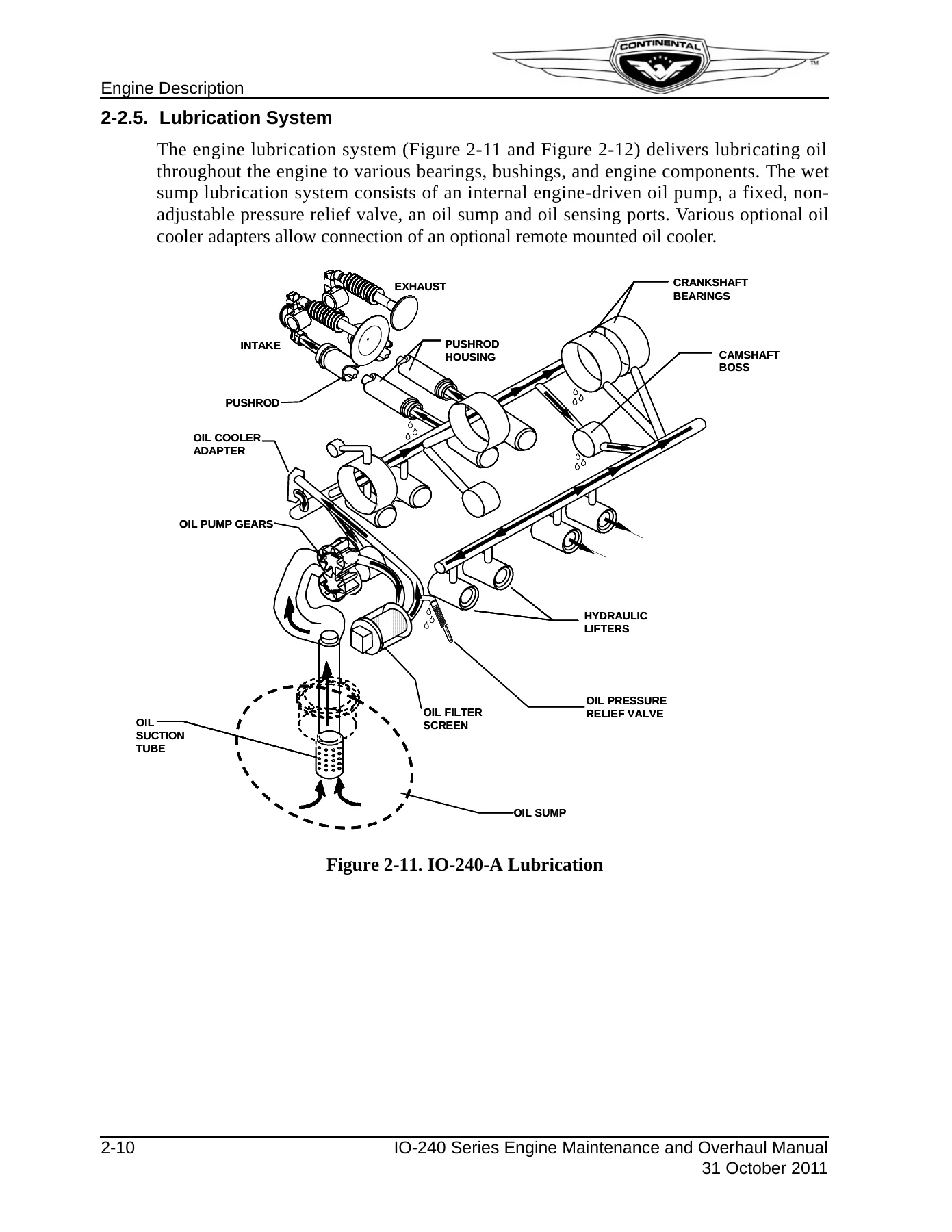
- Chapter 2. Engine Description — model number definition, cylinder numbering, crankcase, drive train (crankshaft, connecting rods, camshaft), accessory case, cylinders and pistons, hydraulic valve tappets, lubrication system, ignition and fuel systems, starter and alternator, cooling and induction, specifications and operating limits, accessory drive ratios, performance charts
- Chapter 3. Special Tools and Supplies — vendor contacts, mechanic tools, lubricants, sealants and adhesives, engine oil specifications, oil change intervals, additives
- Chapter 4. Airworthiness Limitations — mandatory replacement times, mandatory inspection intervals, related procedures, distribution of changes
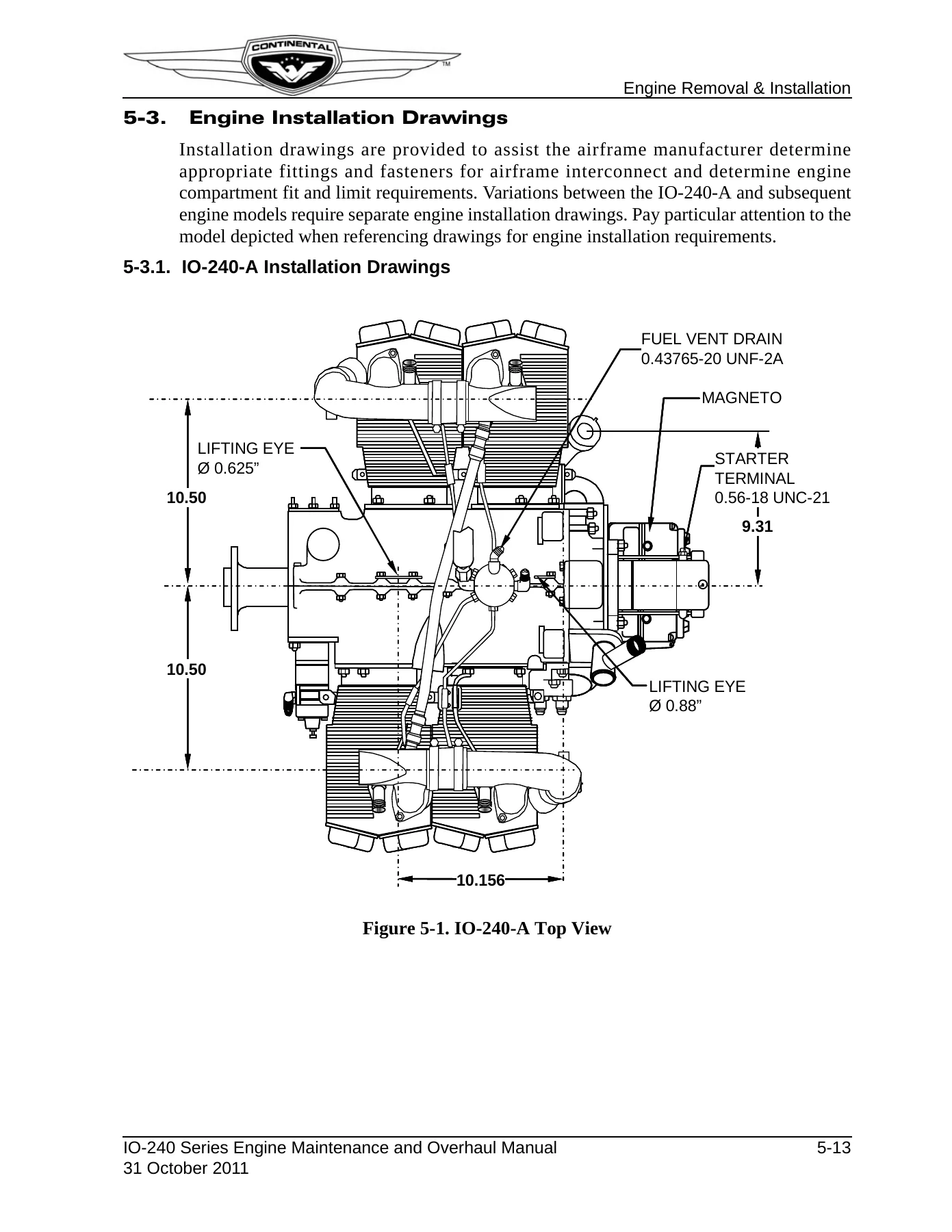
- Chapter 5. Engine Removal and Installation — removal, receipt and handling, airframe and engine preparation, pre-oiling, fuel purge and leak check, installation inspection, preflight and run-up, IO-240-A and IO-240-B installation drawings
- Chapter 6. Engine Inspection and Service — inspection program and schedule; 25-hour, 50-hour, 100-hour and 500-hour inspections; visual inspection; operational check including oil pump, fuel system and magneto timing; oil servicing and spectrographic analysis; ignition, spark plug and harness work; fuel system adjustments; cylinder visual, differential pressure and borescope inspections; crankcase, mounts, induction, gauges, filters, control linkage, drains and alternator; unscheduled work for propeller strike, hydraulic lock, overspeed, lightning, contaminated fuel and foreign objects; inspection checklists
- Chapter 7. Engine Operation — flight prerequisites, oil and fuel requirements, break-in and flight check, start and run-up, shutdown, cold-weather preheat, hot-weather operation, high-density-altitude ground operation
- Chapter 8. Troubleshooting — induction, fuel, charging, starting, ignition harness and spark plugs, lubrication, cylinders, crankcase pressure, exhaust
- Chapter 9. Engine Preservation and Storage — new, unused, temporary and indefinite storage; return to service
- Chapter 10. Non-Overhaul Repair and Replacement — fuel pump, injectors, starter, alternator, magnetos, lubrication components, cylinder and valve-train service, crankshaft nose oil seal, crankcase and exhaust repairs
- Chapter 11. Engine Overhaul Introduction — overhaul schedule, sequence and checklists
- Chapter 12. Engine Disassembly — ignition, fuel injection (standard, altitude-compensating and scavenge), induction, exhaust, oil cooler adapters, starter, alternator, oil sump, accessory case, baffles, cylinders and pistons
- Chapter 13. Component Disassembly — ignition, fuel manifold valve, fuel pump, throttle, starter, accessory case variants, cylinder, crankcase (A and B), camshaft and crankshaft
- Chapter 14. Engine Cleaning — cylinder, piston, exhaust and aluminum cleaning; dry and vapor blasting; protective coatings
- Chapter 15. Overhaul Inspection and Repair — visual, fluorescent penetrant and magnetic particle inspection; dimensional checks of crankcase, drive train, connecting rods, cylinders, lubrication parts and stud heights; fuel, induction, accessory, lubrication and cylinder repairs including honing, valve seats and guides, helical coils, rocker bushings; crankcase machining, welding and line boring; camshaft and crankshaft repair
- Chapter 16. Component Assembly — fuel injection subassemblies and IO-240-B in-line filter, alternator drive hub, starter, exhaust, oil pump and cooler, accessory case builds, cylinder and valve train, crankcase and drive train
- Chapter 17. Engine Assembly — crankcase sealing and hardware, cylinder torque and nose oil seal, oil cooler adapters, baffles, valve train, cylinder drains, accessory case, alternator, starter, oil sump, exhaust, induction and fuel injection (standard, altitude-compensating and scavenge), Continental Motors and Slick ignition installation
- Chapter 18. Post-Overhaul Test and Adjustments — test prerequisites and operating limits, standard acceptance test, oil consumption test
- Appendix A. Glossary
- Appendix B. Torque Specifications — cylinder torque procedure, wrench and extension calculations, general and component-specific torque values
- Appendix C. Standard Practices — parts handling, replacement parts rules, safety wire, tab washers, helical coils, Rosan studs, cotter pins, gasket maker, hose and tubing, harness routing
- Appendix D. Overhaul Dimensional Limits — new-part dimensions and fits for the fuel pump, starter, lubrication system, cylinders, crankcase, drive train and stud height settings by crankcase part number
Taken together, the chapters walk a licensed mechanic from first installation through scheduled inspections and field repairs, then through a complete teardown, inspection to published limits, component rebuild, engine assembly, and post-overhaul acceptance running. Service documents incorporated into the text are listed in the front matter so the reader can see which bulletins were already folded into Publication M-6.
Inspection, Fuel and Ignition Work
Chapter 6 is the day-to-day shop chapter. It sets one-time post-installation and 25-hour initial-operation inspections, then 50-hour, 100-hour (annual) and 500-hour tasks. Operational checks cover oil-pump pressure, unmetered and metered fuel pressure for the standard pump and for the IO-240-B aneroid pump with and without the scavenge valve, magneto-to-engine timing with a timing disk and TDC locator, and idle cut-off mixture. Cylinder work includes visual inspection, a differential pressure test with result tables, borescope criteria with photographs of burned valves, scoring and ring wear, plus baffle and cowling checks that affect cooling.
Approved spark plugs are listed for the series. Ignition harness strain relief, lead routing and a hot magneto test are covered. Unscheduled sections tell the shop what to inspect after a propeller strike, hydraulic lock, Category I–III overspeed, lightning strike, contaminated fuel or foreign-object ingestion.
Overhaul Limits and Shop Data
Chapters 11 through 18 plus Appendix D are the overhaul core of the Continental IO-240-A IO-240-B Aircraft Engine Maintenance and Overhaul Manual M-6. Checklists track visual, fluorescent penetrant, magnetic particle and dimensional inspection. Cylinder repair-versus-replacement guidance, bore surface-finish specifications after honing, valve-seat and valve-guide procedures, rocker-arm bushing replacement and rocker-to-retainer clearance are all written out. Crankcase critical stress areas are illustrated. Drive-train replacement rules, gear backlash and connecting-rod fits sit in Appendix D alongside stud-height tables for IO-240-A crankcase P/N 953277-7 and IO-240-B crankcases P/N 653277-8, 653277-9 and 653277-10.
Appendix B gathers general fastener torque, hose and tube fitting torque, and component-specific values, including the cylinder torque sequence. Chapter 3 lists special tools used for timing, differential pressure testing, borescope work, fuel-injector service, crankcase splitting, valve-guide reaming and nose-oil-seal installation, together with authorized oils meeting SAE J-1899 or SAE J-1966, sealants and adhesives.
Operating Limits Kept with the Engine
Specification tables in Chapter 2 and the operating-limit table in Chapter 7 keep the numbers a technician needs at the bench: 100 or 100-LL fuel, oil pressure 30 to 60 psig in normal operation, 100 psig maximum with cold oil, 10 psig minimum at idle, 240°F maximum oil temperature, 6.0 quart sump capacity with 3.0 quarts usable at the published nose-up and nose-down attitudes, and 460°F maximum cylinder head temperature. Dry basic-engine weight is given as 246.0 lb ± 2.5%. Overall envelope is listed as 23.5 in height, 31.4 in width and 29.8 in length. Installation drawings in Chapter 5 add lifting-eye locations, flange dimensions, fuel and oil connections and magneto schematics for both A and B installations, including the optional oil cooler/filter adapter layout on IO-240-B.
Get the Manual and Use It on the Job
With the Continental IO-240-A IO-240-B Aircraft Engine Maintenance and Overhaul Manual M-6 on hand, a mechanic can install or remove the engine, run the published inspection program, time magnetos, set fuel-pump and mixture values for the pump actually fitted, service cylinders to the differential-pressure and borescope criteria, replace field-serviceable accessories, and take an engine through complete overhaul to the dimensional limits and post-overhaul acceptance test. Using the torque values, fits, timing figures and fuel-pressure charts printed for this series keeps work aligned with the procedures Continental Motors published for these engines. The file is delivered as an instant PDF download after payment—no shipping wait—so it can be opened on a shop computer, tablet or phone and printed for the work stand.
Reviews
There are no reviews yet.