★ TRUSTED BY 321,897+ PROFESSIONALS WORLDWIDE
🏒
Trusted Business
Verified & Licensed
πŸ›‘οΈ
Virus Free Files
100% Safe Downloads
πŸ”’
Secure Payment
SSL Protected
⚑
Instant Delivery
Available Immediately
Sale!

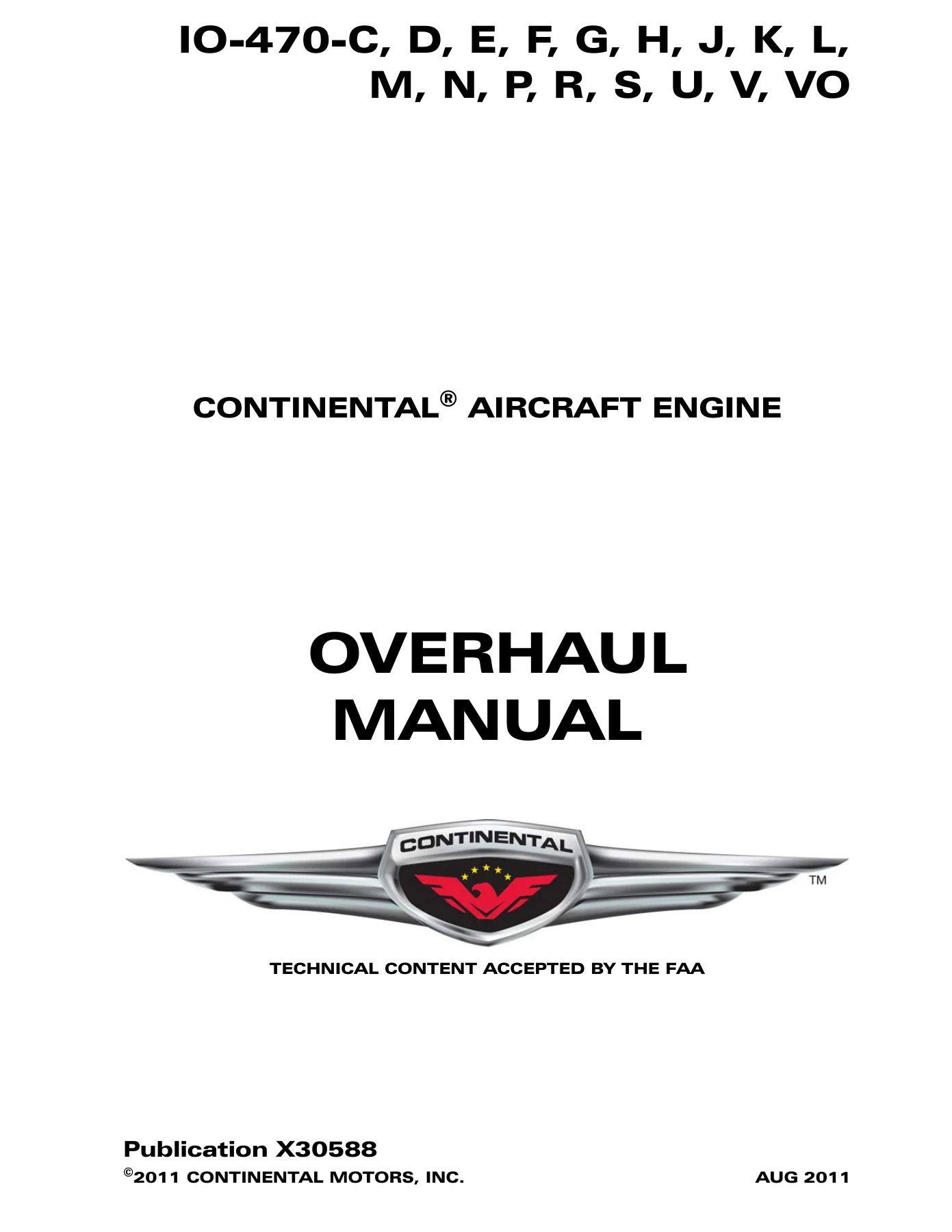
Continental IO-470 Series Aircraft Engine Overhaul Manual X30588A – C, D, E, F, G, H, J, K, L, M, N, P, R, S, U, V & VO Models

Original price was: $39.95.Current price is: $24.95.

Complete Teledyne Continental Motors overhaul manual for the IO-470 series aircraft engine, covering all seventeen dash-number variants from disassembly and inspection through final assembly and overhaul test run. Form X30588A.

⚑
Instant PDF Download
Available immediately
πŸ’Ύ
Save to Your Device
Download & keep forever
πŸ›‘οΈ
Antivirus Scanned
100% virus-free
🌍
Trusted Worldwide
175,000+ customers

Description

Continental IO-470 Series Overhaul Manual – Form X30588A

This is the full Teledyne Continental Motors Overhaul Manual for the IO-470 series aircraft engine, published under form number X30588A and prepared in the GAMA (General Aviation Manufacturers Association) format. It is the document a certified airframe and powerplant mechanic works from when an IO-470 comes off the airframe for major overhaul, and it carries the same chapter and subsystem numbering used across the Continental engine line so that cross-referencing the IO-470 Series Parts Catalog X30589A is direct.

The manual covers the naturally aspirated, fuel injected, air cooled six cylinder horizontally opposed IO-470 in all of its dash-number configurations. Every procedure is written against the actual engine – not a generic reciprocating engine text – with the model-specific differences in fuel injection plumbing, induction layout, oil sump, oil cooler and generator or alternator drive called out model by model.

File Details

  • Manual type: Overhaul Manual (Maintenance and Overhaul Manual)
  • Brand / manufacturer: Teledyne Continental Motors, Aircraft Products Division
  • Engine family: IO-470 series, six cylinder horizontally opposed, fuel injected, air cooled
  • Document number: Form X30588A
  • Companion publication: IO-470 Series Parts Catalog X30589A
  • Language: English
  • Page count: 370 pages
  • File format: PDF
  • Technical content: Accepted by the FAA
  • Revision dates appearing in the document: October 1991 and August 1992

Chapters Covered

  • 1 – Introduction: scope, related publications, service bulletins and service reports, 100% replacement parts, definitions and abbreviations, engine model code, basic design features, special tools, products and application chart of sealants and lubricants
  • 4 – Airworthiness Limitations: mandatory replacement times, mandatory inspection intervals, other related procedures, distribution of changes
  • 5 – Time Limits / Maintenance Checks: general, time limits and inspection program, scheduled maintenance, preflight inspection, 50 hour inspection, 100 hour inspection, unscheduled maintenance
  • 70 – Standard Practices: lockwire procedure, crankcase threading procedure, application of adhesives, installation of gaskets, cylinder leakage check including master orifice assembly tool, static seal and dynamic seal, differential pressure tester, performing the check
  • 72 – Engine Reciprocating: general description of crankcase, crankshaft, connecting rods, camshaft, pistons, lifters, cylinders, gear train, lubrication system, valve mechanism, induction system, exhaust system and ignition system; disassembly; cleaning, repair and replacement; inspection; specific inspections; assembly of subassemblies; final assembly; testing after overhaul; engine preservation
  • 73 – Engine Fuel System: set-up procedure for naturally aspirated and turbocharged engines, fuel pressure regulators, special set-up procedures, fuel system pressure and flow valve charts, fuel system troubleshooting chart
  • 74 – Ignition: TCM ignition system general, magneto installation, harness assembly installation, ignition troubleshooting, Slick ignition system general, magneto installation, harness assembly installation, ignition troubleshooting
  • 75 – Air: induction system components, air throttle assembly, induction manifold, cylinder intake ports
  • 76 – Engine Controls: general, cruise control by performance curve, cruise control by E.G.T., performance charts
  • 77 – Engine Indicating: general, operating limits, engine troubleshooting chart
  • 78 – Exhaust: general
  • 79 – Oil: general, approved products, oil system troubleshooting chart
  • 80 – Starting: prestarting, starting, ground warm-up, pre-takeoff check, flooded engine, cold weather operation, hot weather operation, ground operation at high altitude airports
  • 81 – Turbines

Beyond the chapter list, the working substance of this IO-470 overhaul manual sits in the assembly and inspection sections. The disassembly chapter steps through the ignition system, each of the nine different fuel injection system layouts by engine model, the induction system by model, oil sump, oil cooler, alternator, starter and starter drive adapter, oil pump, cylinders and pistons, crankcase, camshaft and crankshaft. The cleaning and repair chapter then covers cylinders, pistons, valves, rocker shafts, pushrods, camshaft and crankshaft, crankcase, gears, sheet metal and intake manifold, castings, stud replacement, helical coil insert installation, spark plug hole helical coil inserts, fin repairs, valve guides, valve rockers, hydraulic valve lifters, connecting rods, piston pin bushing replacement, crankshaft assembly, idler gear, magneto and accessory drive adapter assembly, tachometer drive housing, starter drive adapter, oil pump assembly and ignition cables. Inspection is split into visual, magnetic particle, ultrasonic, fluorescent particle and dimensional inspection, and is backed by a multi-page table of limits that carries the service limits and new parts limits for gear backlash, cylinder and head assemblies, rocker arms and shafts, pistons, rings and pins, connecting rods, crankshaft, camshaft, crankcase, accessory drive idler assembly, oil pressure pump assembly, oil pressure relief valve assembly, tachometer drive assembly, magneto and accessory drive assembly, starter drive and fuel pump assembly.

The final assembly chapter rebuilds the engine in sequence: crankcase, cylinders and pistons, oil pump, fuel pump, starter drive adapter, alternator or generator, magneto and accessory drive adapters, oil cooler, valve mechanism, oil sump, induction system, fuel injection system, magneto drive gears, placing the crankshaft in timing position, magnetos, ignition harness, fuel lines and hoses and exhaust system. Testing after overhaul sets out the test stand, test club, cooling air scoop, induction air intake, exhaust stacks, controls, electrical wiring, instruments, breather, fuel system and governor pad cover requirements, followed by the standard acceptance test run, oil consumption determination and test flight guidance. The engine preservation chapter closes with flyable storage, temporary storage and indefinite storage procedures.

What This Manual Lets You Do

With this document on the bench, an A&P can tear an IO-470 down to a bare crankcase and build it back up to published fits and limits. That means pulling cylinders and pistons, measuring bore diameter and choke, checking ring gaps and side clearances at the specified 6.34 inch depth, inspecting valve guides and seats, reaming and replacing guides, installing valve seat inserts by the heat-shrink method, checking connecting rod twist and convergence, polishing and inspecting crankshaft journals, checking counterweight bushing diameter across three points, and confirming gear backlash at each mesh point in the train. It also means timing both magnetos to the engine with the correct full advance firing angle for the specific dash number, since the ignition timing table in this manual varies from 20 degrees to 26 degrees BTC depending on model.

The model-specific detail is what makes an overhaul manual worth having. The IO-470-J and K use a straight valve cylinder and a 7:1 compression ratio, run on a lower minimum fuel grade than the rest of the family, and have their own cylinder assembly dimensions, their own reamer series and their own induction layout. The IO-470-C and H share one induction configuration. The D, E, G, L, P, R, U, V and VO share another. The F, J, K, M and S each have their own. The IO-470-P carries a crankshaft extension and housing that no other model uses. The fuel injection chapter alone breaks out separate disassembly sequences for C and H, D and U, E, G, P and R, F, K and N, L, M, S, and V and VO. Getting any of this wrong means parts that do not fit or an engine that does not run right.

Torque values are given in a single consolidated table – crankcase flange, cylinder base stud nuts, through bolts, connecting rod nuts, crankshaft gear screws, camshaft gear bolts, oil pump cover, rocker shaft hold-down bolts, intake flange screws, fuel injection line nuts, spark plug torque and pipe plug torque – with the caution that connecting rod nuts must be torqued to the low limit first and only increased gradually if the cotter pin will not enter.

Why Correct Procedures and Specifications Matter Here

An aircraft engine is not a place to work from memory. The cylinder leakage check section explains the difference between the static seal – valve to seat, spark plug to port, cylinder head to barrel – where no leakage at all is permissible, and the dynamic seal at the piston rings, where leakage varies with cylinder displacement, choke, ring end gap and piston design. It also explains how to calibrate the differential pressure tester against the master orifice tool at 80 psi before trusting any reading, because an uncalibrated gauge produces a false picture of cylinder health. That kind of procedural detail is exactly what separates a serviceable overhaul from one that fails in the field.

Complete PDF Bookmark Tree

Complete Bookmarks

The complete bookmarks in the β€œContinental IO-470 Series Aircraft Engine Overhaul Manual X30588A – C, D, E, F, G, H, J, K, L, M, N, P, R, S, U, V & VO Models” are as follows:

X30588 – OVERHAUL MANUAL – MODELS IO-470-C, D, E, F, G, H, J, K, L, M, N, P, R, S, U, V, VOp. 1
SUPERSEDURE NOTICEp. 2
EFFECTIVE CHANGES FOR THIS MANUALp. 2
LIST OF EFFECTIVE PAGESp. 2
WARNINGp. 3
NOTICEp. 4
INTRODUCTIONp. 5
LIST OF ILLUSTRATIONSp. 6
1-10-04 – THREE QUARTER RIGHT FRONT VIEW OF THE IO-470 SANDCAST SERIES ENGINEp. 22
1-10-04 – INSTALLATION DRAWING IO-470 SERIES ENGINEp. 23
1-20-01 (1) – STRAP WRENCHp. 28
1-20-01 (2) – OIL FILTER CAN CUTTERp. 28
1-20-01 (3) – CYLINDER BASE NUT WRENCHESp. 29
1-20-01 (4) – CYLINDER BASE NUT WRENCHES FOR BONANZA AIRCRAFTp. 29
1-20-01 (5) – CYLINDER BASE NUT, WRENCHp. 29
1-20-01 (5A) – SPARK PLUG WRENCHp. 29
1-20-01 (6) – CYLINDER BASE NUT WRENCHES FOR 0470 AND 520p. 30
1-20-01 (7) – CYLINDER BASE NUT WRENCHES FOR GTSIO 520 F & Kp. 30
1-20-01 (8) – CYLINDER BASE NUT WRENCH FOR CONTINENTAL 550 ENGINEp. 30
1-20-01 (9) – GENERATOR BASE NUT WRENCHESp. 30
1-20-01 (10) – PISTON PIN REMOVERS 8121 SERIESp. 31
1-20-01 (11) – CYLINDER HONEp. 31
1-20-01 (12) – CRANKSHAFT BLADE AND DAMPER BUSING REMOVERS/REPLACERSp. 31
1-20-01 (13) – HOLDING FIXTURE ADAPTERSp. 32
1-20-01 (14) – UNIVERSAL CYLINDER HOLDING FIXTUREp. 32
1-20-01 (15) – VALVE GUIDE CLEANER 122p. 33
1-20-01 (16) – SEAL SEAT CUTTERp. 33
1-20-01 (17) – SPRING CHECKERp. 33
1-20-01 (18) – VALVE GUIDE REMOVERSp. 33
1-20-01 (19) – VALVE GUIDE REPLACERSp. 34
1-20-01 (20) – ROCKER ARM BUSHING REMOVER/INSTALLER SETp. 34
1-20-01 (21) – PISTON RING COMPRESSORSp. 34
1-20-01 (22) – PISTON RING COMPRESSORSp. 34
1-20-01 (23) – FLOATING HOLDERp. 35
1-20-01 (24) – VALVE SPRING COMPRESSORp. 35
1-20-01 (25) – PUSH ROD SPRING COMPRESSORp. 35
1-20-01 (26) – FLARING TOOL FOR PUSH ROD HOUSINGp. 35
1-20-01 (27) – VALVE GUIDE REMOVERp. 35
1-20-01 (28) – VALVE SEAT INSERT REMOVER AND REPLACERp. 36
1-20-01 (29) – VALVE SEAT INSERT REMOVER AND REPLACERp. 36
1-20-01 (30) – INSTALLER VALVE SEAT INSERTSp. 36
1-20-01 (31) – VALVE GUIDE TO VALVE SEAT ALIGNMENT SYSTEMp. 37
1-20-01 (32) – VALVE GUIDE TO VALVE SEAT ALIGNMENT SYSTEMp. 37
1-20-01 (33) – COMMON PARTS KITp. 37
1-20-01 (34) – VALVE STEM HOLE REAMERSp. 38
1-20-01 (35) – BORING BARSp. 38
1-20-01 (36) – BORING BARSp. 38
1-20-01 (37) – EXPANDING GUIDE BODIESp. 38
1-20-01 (38) – VALVE SEAT INSERT CUTTERSp. 39
1-20-01 (39) – ROSAN STUD REMOVERp. 39
1-20-01 (40) – CONNECTING ROD REAMING AND ALIGNMENT CHECKING FIXTUREp. 40
1-20-01 (41) – ADAPTER KITSp. 40
1-20-01 (42) – REAMERS, CONNECTING ROD BUSHINGp. 40
1-20-01 (43) – UNIVERSAL CONNECTING ROD BUSHING REMOVER AND INSTALLER SETp. 41
1-20-01 (44) – COMMON DRIVE HANDLE AND PILOTSp. 41
1-20-01 (45) – NEEDLE BEARING INSTALLERSp. 42
1-20-01 (46) – HYDRAULIC CRANKSHAFT DAMPENER BUSHING REMOVER/REPLACER SETp. 42
1-20-01 (47) – COUNTER WEIGHT BUSHING REMOVER/INSTALLERp. 42
1-20-01 (48) – ALL POSITION ENGINE STANDp. 43
1-20-01 (49) – TORK BAND TENSION ADJUSTERp. 43
1-20-01 (50) – GENERATOR DRIVE HOLDERSp. 43
1-20-01 (51) – CYLINDER HEATING STANDp. 44
1-20-01 (52) – BLIND NEEDLE BEARING PULLERp. 44
1-20-01 (53) – STARTER CLUTCH SHAFT BEARING PULLERSp. 44
1-20-01 (54) – DIFFERENTIAL PRESSURE GAUGEp. 45
1-20-01 (55) – DIFFERENTIAL PRESSURE CYLINDER CHECKERp. 45
1-20-01 (56) – BELT TENSION GAUGEp. 45
1-20-01 (57) – HYDRAULIC VALVE LIFTER TESTERp. 45
1-20-01 (58) – IN AIRCRAFT ALTERNATOR GENERATOR TESTERp. 46
1-20-01 (59) – ENGINE TIMING DISCp. 46
1-20-01 (60) – PULLEY HOLDERp. 46
1-20-01 (61) – PULLEY ALIGNMENT GAGE BARp. 46
1-20-01 (62) – CRANKCASE DRILL FIXTURE FOR STARTER CLUTCH ADAPTERp. 47
1-20-01 (63) – VACUUM PUMPp. 47
1-20-01 (64) – GENERATOR PULLEY PULLERp. 47
1-20-01 (65) – BEARING AND BUSHING DRILL FIXTUREp. 47
1-20-01 (66) – SPARK PLUG INSERT REPLACERp. 48
1-20-01 (67) – THRU-BOLT BORE STEP CUTTERSp. 48
1-20-01 (68) – SPARK PLUG INSERT TAPp. 48
1-20-01 (69) – SPARK PLUG INSERT REMOVERp. 48
1-20-01 (70) – SLIDE HAMMERp. 48
1-20-01 (71) – SPARK PLUG TAPp. 48
1-20-01 (72) – ROSAN LOCK RING INSTALLERp. 49
1-20-01 (73) – STUD DRIVERSp. 49
1-20-01 (74) – SCAVENGE PUMP DRILL FIXTUREp. 49
1-20-01 (75) – CRANKCASE SPLITTER SETp. 49
1-20-01 (76) – PROPELLER SHAFT OIL SEAL INSTALLERp. 50
1-20-01 (77) – OIL PRESSURE RELIEF SPOT FACERSp. 50
1-20-01 (78) – RUNOUT BLOCK SETp. 50
1-20-01 (79) – POLISHING TOOLS FOR CRANKSHAFT BEARINGSp. 50
1-20-01 (80) – INJECTOR NOZZLE REMOVER AND INSTALLERp. 51
1-20-01 (81) – CRANKCASE THRU-BOLT REMOVERSp. 51
1-20-01 (82) – HEX DRIVE FOR HEX TUBE NUTSp. 51
1-20-01 (83) – ROTABROACH CUTTERSp. 51
1-20-01 (84) – PULLERSp. 52
1-20-01 (85) – PULLERSp. 52
1-20-01 (86) – PULLERSp. 52
1-20-01 (87) – PULLERSp. 52
1-20-01 (88) – OUTSIDE MICROMETERSp. 53
1-20-01 (89) – DIAL BORE GAGESp. 53
1-20-01 (90) – BLADE MICROMETERSp. 54
1-20-01 (91) – SCREW THREAD MICROMETERp. 54
1-20-01 (92) – DEPTH MICROMETERSp. 54
1-20-01 (93) – REAMERS, ROCKER SHAFT SUPPORT BOSSp. 55
1-20-01 (94) – REAMERS, VALVE GUIDE BOSSp. 55
1-20-01 (95) – VALVE GUIDE STEM HOLE REAMERSp. 56
1-20-01 (96) – ADAPTER, SQUARE SHANK REAMERSp. 56
1-20-01 (97) – PLUG GAUGES VALVE STEM HOLEp. 56
1-20-01 (98) – DIAL THICKNESS GAGEp. 57
1-20-01 (99) – PRECISION VERNIER CALIPERSp. 57
1-20-01 (100) – INSIDE MEASURING INSTRUMENTSp. 57
1-20-01 (101) – OUTSIDE MICROMETERSp. 57
1-20-01 (102) – ALTERNATOR ANALYZERp. 58
1-20-01 (103) – ALTERNATOR/REGULATOR/BATTERY TESTERp. 58
1-20-01 (104) – MULTIPLE VOLTAGE & CIRCUIT TESTERp. 58
1-20-01 (105) – DIFFERENTIAL CYLINDER PRESSURE TESTERp. 59
1-20-01 (106) – AIRCRAFT TIMING INDICATORp. 59
1-20-01 (107) – AIRCRAFT MAGNETO TIMING LIGHTp. 59
1-20-01 (108) – COLD CYLINDER TESTERp. 60
1-20-01 (109) – HI-VOLTAGE CABLE TESTERp. 60
1-20-01 (110) – MASTER ORIFICE TOOLp. 60
1-20-01 (111) – ALCOR PORTABLE DIGITAL EGT UNITp. 61
1-20-01 (112) – ALCOR PORTABLE DIGITAL CHT UNITp. 61
70-10-00 – LOCKWIRE PROCEDUREp. 93
70-20-00 – PERMATEX AND THREADING PROCEDUREp. 94
70-50-01 – MASTER ORIFICE ASSEMBLY TOOLp. 96
70-50-02 – CYLINDER STATIC SEAL & DYNAMIC SEALp. 96
70-50-03 – DIFFERENTIAL PRESSURE TESTERp. 98
70-50-04 – DYNAMIC SEAL CHECKp. 100
72-00-03 – CRANKSHAFT NUMBERINGp. 112
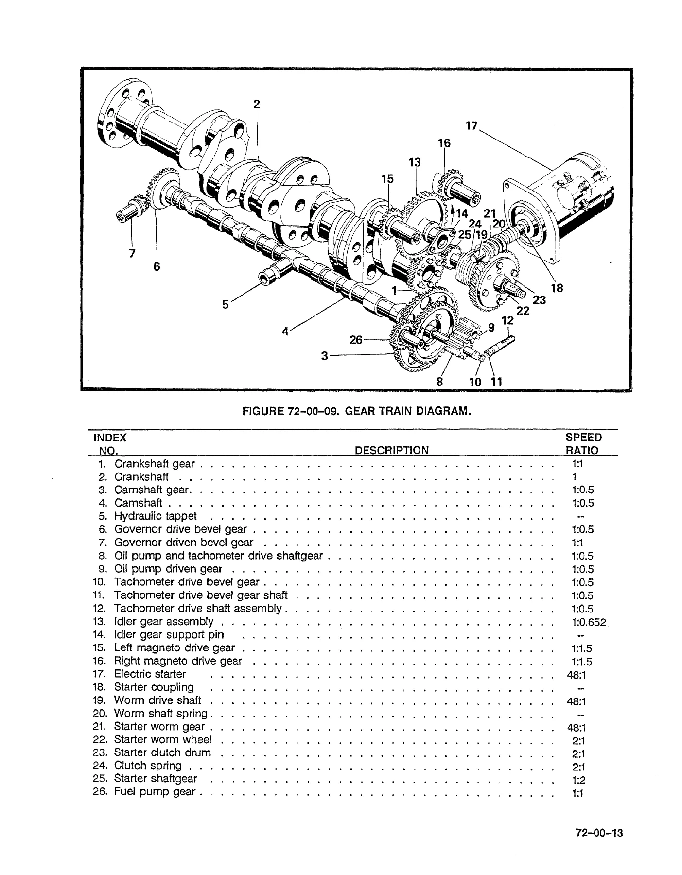
72-00-09 – GEAR TRAIN DIAGRAMp. 115
72-00-10 – LUBRICATION SYSTEMp. 117
72-00-11 – HYDRAULIC LIFTERp. 118
72-10-05 – EXPLODED VIEW OF IGNITION SYSTEMp. 125
72-10-06A – FUEL INJECTION SYSTEM IO-470-C, H & Jp. 127
72-10-06B – FUEL INJECTION SYSTEM IO-470-D & Up. 129
72-10-06C – FUEL INJECTION SYSTEM IO-470,E,G, P & Rp. 131
72-10-06D – FUEL INJECTION SYSTEM IO-470-Fp. 133
72-10-06E – FUEL INJECTION SYSTEM IO-470-K& Np. 135
72-10-06F – FUEL INJECTION SYSTEM IO-470-Lp. 137
72-10-06G – FUEL INJECTION SYSTEM IO-470-Mp. 139
72-10-06H – FUEL INJECTION SYSTEM IO-470-Sp. 141
72-10-06I – FUEL INJECTION SYSTEM IO-470-V & VOp. 143
72-10-07A – INDUCTION SYSTEM IO-470-C & Hp. 144
72-10-07B – INDUCTION SYSTEM IO-470-D,E,G,L,P,R,U, V & VOp. 145
72-10-07C – INDUCTION SYSTEM IO-470-Fp. 146
72-10-07D – INDUCTION SYSTEM IO-470-Jp. 147
72-10-07E – INDUCTION SYSTEM IO-470-K & Np. 148
72-10-07F – INDUCTION SYSTEM IO-470-Mp. 149
72-10-07G – INDUCTION SYSTEM IO-470-Sp. 150
72-10-08 – MAGNETO & ACCESSORY DRIVESp. 151
72-10-09A – OIL SUMP IO-470,C,H,J, & Np. 152
72-10-09B – OIL SUMP IO-470,D,E,F,G,L,M,P,R,S, U & Vp. 153
72-10-10A – OIL COOLER IO-470-Fp. 154
72-10-10B – OIL COOLER IO-470,C,E,G,H,J,K,N, R & Sp. 155
72-10-10C – OIL COOLER IO-470,D,L,M,N, U & Vp. 156
72-10-11A – GENERATOR IO-470,C,D,E,F,G,H,J,K,L,N,P, R & Sp. 157
72-10-11B – GENERATOR IO-470-Mp. 158
72-10-11C – GENERATOR IO-470-U & Vp. 159
72-10-11 – ALTERNATOR, ALL MODELSp. 160
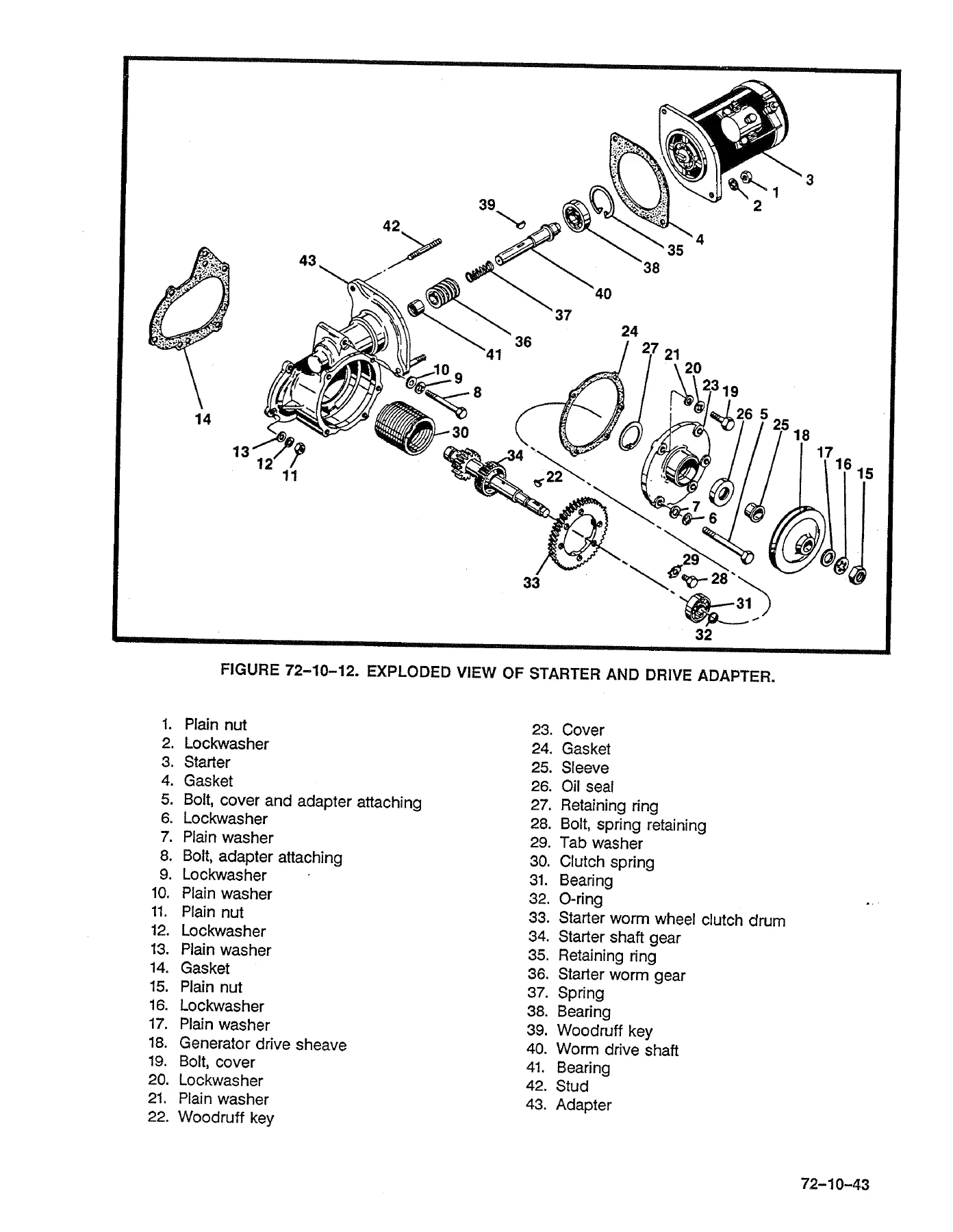
72-10-12 – STARTER AND STARTER DRIVE ADAPTERp. 163
72-10-13A – OIL PUMP ASSEMBLYp. 165
72-10-13B – OIL PUMP COVER AND TACHOMETER DRIVEp. 166
72-10-14A – CYLINDER AND PISTON ASSEMBLY (ALL EXCEPT IO-470-J & K)p. 169
72-10-14B – CYLINDER AND PISTON ASSEMBLY IO-470-J & Kp. 170
72-10-15A – CRANKCASE ASSEMBLYp. 173
72-10-15B – LEFT C/C & SHAFTS SUPPORTED FOR DISMANTLING OR FINAL ASSEMBLYp. 174
72-10-15C – C/C & CIS EXTENSION (IO-470-P)p. 175
72-10-16 – CAMSHAFT ASSEMBLYp. 176
72-10-17 – CRANKSHAFT GROUPp. 177
72-20-12A – CRANKCASE STUD SETTING HEIGHTSp. 185
72-20-12B – STANDARD & OVERSIZED STUD IDENTIFICATIONp. 185
72-20-13A – HELICOIL & SPECIAL TOOL DATAp. 187
72-20-13B – INSTALLING TYPICAL HELICAL INSERTp. 188
72-20-14A – INSTALLING SPARK PLUG HOLE HELICAL INSERTp. 188
72-20-14B – EXPANDING SPARK PLUG HOLE HELICAL INSERTp. 188
72-20-14C – REMOVING SPARK PLUG HOLE HELICAL INSERTp. 188
72-20-15A – CYLINDER ASSEMBLY DIMENSIONS (INCLINED VALVE)p. 189
72-20-15B – CYLINDER ASSEMBLY DIMENSIONS (STRAIGHT VALVE)p. 190
72-20-17 – VALVE, ROCKER BUSHING DIMENSIONSp. 188
72-20-18 – HYDRAULIC LIFTERp. 192
72-20-20 – CONNECTING ROD AND BUSHING DIMENSIONSp. 193
72-20-27 – IGNITION WIRING DIAGRAMp. 196
72-30-04 – CRANKSHAFT ULTRASONIC INSPECTION PROCEDUREp. 204
72-40-03 – COUNTERWEIGHT BUSHING DIAMETER CHECKp. 228
72-40-07A – INSPECTION RING SIDE CLEARANCEp. 229
72-40-07B – MEASURING RING GAP IN CYLINDERp. 229
72-40-08 – PISTON TO CYLINDER DOME CLEARANCEp. 230
72-40-13A – SPARK PLUGSp. 232
72-40-13B – REVERSE SPARK PLUG PROCEDUREp. 232
72-50-04 – VALVE SPRING INSTALLATIONp. 247
72-50-10A – FUEL MANIFOLD VALVE FITTING ORIENTATIONp. 252
72-50-10B – FUEL CONTROL VALVE FITTING ORIENTATIONp. 253
72-50-10C – FUEL PUMP FITTING LOCATIONS FOR ALL (EXCEPT IO-470-V, VO)p. 254
72-50-10E – FUEL PUMP FITTING LOCATIONS FOR IO-470-V & VOp. 255
72-60-02 – IDLER GEAR, SUPPORT PIN AND TIMING MARKSp. 260
72-60-02 – TORQUING SEQUENCEp. 261
72-60-02 – LEFT SIDE OF COMPLETE CRANKCASE ON STANDp. 262
72-60-03 – INSTALLING NO. 5 CYLINDERp. 263
72-60-03 – TIGHTENING CYLINDER BASE NUTp. 263
72-60-03 – CYLINDER FLANGE TORQUE SEQUENCE FOR SINGLE CYLINDER INSTALLATIONp. 264
72-60-04 – OIL PUMP, FUEL PUMP AND STARTER ADAPTER INSTALLEDp. 264
72-60-10 – INSTALLING PUSHROD HOUSINGp. 268
72-60-11 – BOTTOM VIEW WITH VALVE MECHANISM AND OIL SUMP SUCTION TUBEp. 268
72-60-14 – POSITION OF MAGNETO COUPLINGSp. 272
72-60-17 – IGNITION WIRING DIAGRAMp. 275
72-70-05 – EXHAUST FLANGE DIMENSIONSp. 280
73-00-00 – FUEL SYSTEM SCHEMATICp. 297
74-00-04 – COATING INSULATING SLEEVEp. 305
74-00-04 – INSTALLATION OF ELBOW CLAMPp. 305
LIST OF CHARTSp. 10
1-10-04 – ENGINE DIMENSIONSp. 10
1-20-01 – SPECIAL TOOLS PROCUREMENT SOURCESp. 26
1-20-01 – IDENTIFICATION CODE FOR TOOLSp. 27
1-20-01 – SPECIAL TOOL INDEXp. 63
1-30-00 – APPLICATION CHART SEALANTS/LUBRICANTSp. 77
70-50-05 – CYLINDER LEAKAGE CHECKp. 101
72-20-12A – CRANKCASE STUD SETTING HEIGHTSp. 185
72-20-12B – STANDARD AND OVERSIZE STUD LDENTIFICATIONp. 185
72-30-03 – MAGNETIC PARTICLE INSPECTIONp. 201
72-30-08 – TABLE OF LIMITS CHART (1)p. 207
72-30-08 – TABLE OF LIMITS CHART (2)p. 208
72-30-08 – TABLE OF LIMITS CHART (3)p. 212
72-30-08 – TABLE OF LIMITS CHART (4)p. 215
72-30-08 – TABLE OF LIMITS CHART (5)p. 218
72-30-09 – CRITICAL NEW PART DIMENSIONSp. 221
72-40-15 – INSPECTION CHARTp. 233
72-50-01 – GENERAL USE – TIGHTENING TORQUESp. 243
72-50-01 – TABLE OF TIGHTENING TORQUESp. 244
72-50-01 – PIPE PLUGSp. 244
72-50-10A – FUEL MANIFOLD VALVE FITTING LOCATIONSp. 252
72-50-10B – FUEL CONTROL VALVE FITTING LOCATIONSp. 253
72-50-10C – FUEL PUMP FITTING LOCATIONS FOR ALL IO-470 (EXCEPT IO-470-V & VO)p. 254
72-50-10D – FUEL PUMP FITTING LOCATIONS FOR (IO-470-V & VO)p. 255
72-60-02 – CRANKCASE ASSEMBLY PROCEDUREp. 10
72-60-15 – MAGNETO-TO-ENGINE TIMINGp. 10
72-70-14 – STANDARD ACCEPTANCE TESTp. 282
72-70-14 – OIL CONSUMPTION DETERMINATIONp. 283
72-70-14 – TEST OPERATING LIMITSp. 284
73-10-06 – FUEL INJECTION SYSTEM TROUBLESHOOTING CHARTp. 300
74-00-04 – COUPLING NUT TORQUE VALUES (TCM)p. 306
74-20-00 – IGNITION TROUBLESHOOTING (TCM)p. 307
74-30-04 – COUPLING NUT TORQUE VALUES (SLICK)p. 310
74-50-00 – IGNITION TROUBLESHOOTING (SLICK)p. 311
76-30-00 – PERFORMANCE CHARTSp. 320
77-10-00 – OPERATING LIMITSp. 344
77-20-00 – ENGINE TROUBLE SHOOTINGp. 346
79-10-00 – APPROVED OIL PRODUCTSp. 357
79-20-00 – LUBRICATION SYSTEM TROUBLESHOOTINGp. 358
CHAPTER 1 – INTRODUCTIONp. 11
1-00-00 – SCOPEp. 13
1-00-01 – RELATED PUBLICATIONSp. 13
1-00-02 – SERVICE BULLETINSp. 14
1-00-03 – SERVICE REPORTS AND INQUIRIESp. 14
1-00-04 – 100% REPLACEMENT PARTSp. 14
1-10-00 – DEFINITIONS & ABBREVIATIONSp. 15
1-10-01 – ABBREVIATION/SYMBOLSp. 15
1-10-02 – DEFINITIONSp. 17
1-10-03 – DESCRIPTION OF ENGINE MODEL CODEp. 21
1-10-04 – BASIC DESIGN FEATURESp. 21
1-20-00 – TOOLSp. 25
1-20-01 – SPECIAL TOOLSp. 25
1-30-00 – PRODUCTSp. 76
1-30-01 – PRODUCT LISTp. 11
CHAPTER 4 – AIRWORTHINESS LIMITATIONSp. 81
CHAPTER 5 – TIME LIMITS/MAINTENANCE CHECKSp. 85
5-00-00 – GENERALp. 87
5-10-00 – TIME LIMITS/INSPECTION PROGRAMp. 87
5-20-00 – SCHEDULED MAINTENANCEp. 87
5-20-01 – PREFLIGHT INSPECTIONp. 87
5-20-02 – 50 HOUR INSPECTIONp. 87
5-20-03 – 100 HOUR INSPECTIONp. 88
5-30-00 – UNSCHEDULED MAINTENANCEp. 90
CHAPTER 70 – STANDARD PRACTICESp. 91
70-00-00 – GENERALp. 92
70-10-00 – LOCKWIRE PROCEDUREp. 93
70-20-00 – CRANKCASE THREADING PROCEDUREp. 94
70-30-00 – APPLICATION OF ADHESIVESp. 95
70-40-00 – INSTALLATION OF GASKETSp. 95
70-50-00 – CYLINDER LEAKAGE CHECKp. 95
70-50-01 – LEAKAGE CHECKSp. 97
70-50-02 – EQUIPMENTp. 97
70-50-03 – PERFORMING THE CHECKp. 98
CHAPTER 72 – ENGINE RECIPROCATINGp. 103
72-00-00 – GENERALp. 106
72-00-01 – INTRODUCTIONp. 111
72-00-02 – CRANKCASEp. 111
72-00-03 – CRANKSHAFTp. 111
72-00-04 – CONNECTING RODSp. 112
72-00-05 – CAMSHAFTp. 113
72-00-06 – PISTONSp. 113
72-00-07 – LIFTERSp. 113
72-00-08 – CYLINDERSp. 113
72-00-09 – GEAR TRAINp. 113
72-00-10 – LUBRICATION SYSTEMp. 116
72-00-11 – VALVE MECHANISMp. 118
72-00-12 – INDUCTION SYSTEMp. 118
72-00-13 – EXHAUST SYSTEMp. 119
72-00-14 – IGNITION SYSTEMp. 119
72-10-00 – DISASSEMBLYp. 121
72-10-01 – GENERALp. 123
72-10-02 – EXTENT OF DISASSEMBLYp. 124
72-10-03 – PARTS TO BE DISCARDEDp. 124
72-10-04 – PRELIMINARY CLEANINGp. 124
72-10-05 – IGNITION SYSTEMp. 124
72-10-06 – FUEL INJECTION SYSTEMp. 126
72-10-07 – MAGNETO AND ACCESSORY DRIVESp. 151
72-10-08 – INDUCTION SYSTEMp. 144
72-10-09 – OIL SUMPp. 152
72-10-10 – OIL COOLERp. 154
72-10-11 – ALTERNATOR ASSEMBLYp. 160
72-10-12 – STARTER AND STARTER DRIVE ADAPTERp. 162
72-10-13 – OIL PUMP ASSEMBLYp. 164
72-10-14 – CYLINDERS AND PISTONSp. 167
72-10-15 – CRANKCASEp. 172
72-10-16 – CAMSHAFT ASSEMBLYp. 176
72-10-17 – CRANKSHAFT GROUPp. 176
72-10-18 – EXHAUST SYSTEMp. 178
72-10-19 – OPTIONAL ACCESSORIESp. 103
72-20-00 – CLEANING, REPAIR AND REPLACEMENTp. 179
72-20-01 – GENERALp. 181
72-20-02 – CYLINDERSp. 181
72-20-03 – PISTONSp. 181
72-20-04 – VALVESp. 182
72-20-05 – ROCKER SHAFTSp. 182
72-20-06 – PUSHRODS, VALVE ROCKERS AND OTHER SMALL STEEL PARTSp. 182
72-20-07 – CAMSHAFT AND CRANKSHAFTp. 182
72-20-08 – CRANKCASEp. 182
72-20-09 – GEARSp. 182
72-20-10 – SHEET METAL PARTS AND INTAKE MANIFOLDp. 182
72-20-11 – CASTINGSp. 182
72-20-12 – STUD REPLACEMENTp. 183
72-20-13 – HELICAL COIL INSERT INSTALLATIONp. 186
72-20-14 – SPARK PLUG HOLE HELICAL COIL INSERTSp. 191
72-20-15 – FIN REPAIRSp. 191
72-20-16 – VALVE GUIDESp. 191
72-20-17 – VALVE ROCKERSp. 192
72-20-18 – HYDRAULIC VALVE LIFTERSp. 192
72-20-19 – CONNECTING RODSp. 193
72-20-20 – PISTON PIN BUSHING REPLACEMENTp. 193
72-20-21 – CRANKSHAFT ASSEMBLYp. 193
72-20-22 – IDLER GEARp. 194
72-20-23 – MAGNETO AND ACCESSORY DRIVE ADAPTER ASSEMBLYp. 194
72-20-24 – TACHOMETER DRIVE HOUSINGp. 194
72-20-25 – STARTER DRIVE ADAPTERp. 195
72-20-26 – OIL PUMP ASSEMBLYp. 195
72-20-27 – IGNITION CABLESp. 195
72-30-00 – INSPECTIONp. 197
72-30-01 – GENERALp. 199
72-30-02 – VISUAL INSPECTIONp. 200
72-30-03 – MAGNETIC PARTICLE INSPECTIONp. 200
72-30-04 – ULTRASONIC INSPECTIONp. 202
72-30-05 – FLOURESCENT PARTICLE INSPECTIONp. 205
72-30-06 – DIMENSIONAL INSPECTIONp. 205
72-30-07 – DIMENSIONAL LIMITSp. 205
72-30-08 – TABLE OF LIMITSp. 207
72-30-09 – ORIGINAL DIMENSIONp. 221
72-30-10 – PROTECTIVE COATINGp. 224
72-30-11 – APPLICATION OF ANODIZINGp. 224
72-30-12 – REPAIR OF ANODIZED SURFACESp. 224
72-30-13 – ENAMEL COATINGSp. 224
72-40-00 – SPECIFIC INSPECTIONSp. 225
72-40-01 – CRANKCASEp. 227
72-40-02 – CRANKSHAFTp. 227
72-40-03 – CRANKSHAFT AND COUNTERWEIGHT PINS AND BUSHINGSp. 227
72-40-04 – CAMSHAFTp. 228
72-40-05 – CONNECTING RODSp. 228
72-40-06 – GEARSp. 228
72-40-07 – PISTONS AND RINGSp. 228
72-40-08 – CYLINDERSp. 230
72-40-09 – HYDRAULIC VALVE LIFTERSp. 231
72-40-10 – INTAKE TUBESp. 231
72-40-11 – LUBRICATION SYSTEMp. 231
72-40-12 – FUEL INJECTION SYSTEMp. 231
72-40-13 – IGNITION SYSTEMp. 231
72-40-14 – EXHAUST SYSTEMp. 232
72-40-15 – INSPECTION CHARTp. 233
72-50-00 – ASSEMBLY OF SUBASSEMBLIESp. 241
72-50-01 – GENERALp. 243
72-50-02 – OIL PUMP ASSEMBLYp. 245
72-50-03 – STARTER AND DRIVE ASSEMBLYp. 245
72-50-04 – CYLINDER ASSEMBLYp. 246
72-50-05 – PISTON AND RING ASSEMBLIESp. 247
72-50-06 – PUSHROD HOUSINGp. 247
72-50-07 – CRANKSHAFT AND CONNECTING RODSp. 247
72-50-08 – CAMSHAFTp. 248
72-50-09 – CRANKCASEp. 248
72-50-10 – FUEL INJECTION CONTROL AND AIR THROTTLE BODY ASSEMBLYp. 249
72-60-00 – FINAL ASSEMBLYp. 257
72-60-01 – GENERALp. 259
72-60-02 – CRANKCASEp. 259
72-60-03 – CYLINDERS AND PISTONSp. 263
72-60-04 – OIL PUMPp. 264
72-60-05 – FUEL PUMPp. 265
72-60-06 – STARTER DRIVE ADAPTERp. 265
72-60-07 – ALTERNATOR ASSEMBLYp. 265
72-60-08 – MAGNETO AND ACCESSORY DRIVE ADAPTERSp. 265
72-60-09 – OIL COOLERp. 265
72-60-10 – VALVE MECHANISMp. 266
72-60-11 – OIL SUMPp. 266
72-60-12 – INDUCTION SYSTEMp. 269
72-60-13 – FUEL INJECTION SYSTEMp. 270
72-60-14 – MAGNETO DRIVE GEARSp. 272
72-60-15 – PLACING CRANKSHAFT IN TIMING POSITIONp. 273
72-60-16 – MAGNETOSp. 274
72-60-17 – IGNITION HARNESSp. 274
72-60-18 – FUEL LINESp. 276
72-60-19 – EXHAUST SYSTEMp. 276
72-70-00 – TESTING AFTER OVERHAULp. 277
72-70-01 – TEST STANDp. 279
72-70-02 – TEST CLUBp. 279
72-70-03 – COOLING AIR SCOOPp. 279
72-70-04 – INDUCTION AIR INTAKEp. 279
72-70-05 – EXHAUST STACKSp. 279
72-70-06 – CONTROLSp. 279
72-70-07 – ELECTRICAL WIRINGp. 280
72-70-08 – INSTRUMENTSp. 280
72-70-09 – BREATHERp. 280
72-70-10 – FUEL SYSTEMp. 281
72-70-11 – GOVERNOR PAD COVERp. 281
72-70-12 – ENGINE TESTp. 281
72-70-13 – STARTING PROCEDUREp. 281
72-70-14 – OVERHAUL TEST RUNp. 282
72-80-00 – ENGINE PRESERVATIONp. 287
72-80-01 – GENERALp. 289
72-80-02 – FLYABLE STORAGEp. 289
72-80-03 – TEMPORARY STORAGEp. 290
72-80-04 – INDEFINITE STORAGEp. 291
CHAPTER 73 – ENGINE FUEL SYSTEMp. 295
73-00-00 – ENGINE FUEL SYSTEMp. 297
73-10-00 – SET-UP PROCEDUREp. 298
73-10-01 – NATURALLY ASPIRATED ENGINESp. 298
73-10-02 – TURBOCHARGED ENGINESp. 295
73-10-03 – FUEL PRESSURE REGULATORSp. 295
73-10-04 – SPECIAL SET-UP PROCEDURESp. 295
73-10-05 – FUEL SYSTEM PRESSURE AND FLOW VALVE CHARTSp. 295
73-10-06 – FUEL SYSTEM TROUBLESHOOTING CHARTp. 300
CHAPTER 74 – IGNITIONp. 303
(TCM IGNITION SYSTEM)p. 304
74-00-00 – GENERALp. 304
74-00-01 – MAGNETO INSTALLATIONp. 304
74-00-02 – HARNESS ASSEMBLY INSTALLATIONp. 305
74-10-00 – IGNITION TROUBLESHOOTINGp. 307
(SLICK IGNITION SYSTEM)p. 308
74-30-00 – GENERALp. 308
74-30-01 – MAGNETO INSTALLATIONp. 308
74-30-02 – HARNESS ASSEMBLY INSTALLATIONp. 309
74-50-00 – IGNITION TROUBLESHOOTINGp. 311
CHAPTER 75 – AIRp. 313
75-00-00 – GENERALp. 315
CHAPTER 76 – ENGINE CONTROLSp. 317
76-00-00 – GENERALp. 319
76-10-00 – CRUISE CONTROL BY PERFORMANCE CURVEp. 319
76-20-00 – CRUISE CONTROL BY E.G.T.p. 319
76-30-00 – PERFORMANCE CHARTSp. 320
CHAPTER 77 – ENGINE INDICATINGp. 341
77-00-00 – GENERALp. 343
77-10-00 – OPERATING LIMITSp. 344
77-20-00 – ENGINE TROUBLESHOOTING CHARTp. 346
CHAPTER 78 – EXHAUSTp. 353
78-00-00 – GENERALp. 354
CHAPTER 79 – OILp. 355
79-00-00 – GENERALp. 357
79-10-00 – APPROVED PRODUCTSp. 357
79-20-00 – OIL SYSTEM TROUBLESHOOTING CHARTp. 358
CHAPTER 80 – STARTINGp. 359
80-00-00 – GENERALp. 361
80-00-01 – PRESTARTINGp. 361
80-00-02 – STARTINGp. 361
80-00-03 – GROUND WARM-UPp. 362
80-00-04 – PRE-TAKEOFF CHECKp. 362
80-00-05 – FLOODED ENGINEp. 364
80-00-06 – COLD WEATHER OPERATIONp. 364
80-00-07 – PREHEATINGp. 365
80-00-08 – HOT WEATHER OPERATIONp. 366
80-00-09 – GROUND OPERATION AT HIGH ALTITUDE AIRPORTSp. 367
CHAPTER 81 – TURBINESp. 369
81-00-00 – GENERAL (NOT APPLICABLE)p. 370

The same applies to the 100% replacement parts list, the mandatory replacement and inspection intervals in the airworthiness limitations chapter, and the oil change and filter intervals in the time limits chapter. All of it is in here.

IMAGES PREVIEW

Continental IO-470 Series Aircraft Engine Overhaul Manual X30588A - C, D, E, F, G, H, J, K, L, M, N, P, R, S, U, V & VO Models β€” PDF page 1 preview
Continental IO-470 Series Aircraft Engine Overhaul Manual X30588A - C, D, E, F, G, H, J, K, L, M, N, P, R, S, U, V & VO Models β€” PDF page 115 preview
Continental IO-470 Series Aircraft Engine Overhaul Manual X30588A - C, D, E, F, G, H, J, K, L, M, N, P, R, S, U, V & VO Models β€” PDF page 163 preview

Instant PDF Delivery

This Continental IO-470 Series Overhaul Manual X30588A is delivered as a PDF file immediately after purchase. There is no shipping, no waiting and no physical book to keep track of. Open it on a laptop in the hangar, on a tablet on the bench, or print the pages you need for the job in front of you – the tables of limits, the torque table and the exploded views are all printable. Whether you are doing a top overhaul on a single IO-470-K or a full major on an IO-470-L, the procedure, the fit and the limit are on the page you are working from.
Reviews

There are no reviews yet.

Be the first to review “Continental IO-470 Series Aircraft Engine Overhaul Manual X30588A – C, D, E, F, G, H, J, K, L, M, N, P, R, S, U, V & VO Models”

What Our Customers Say

β˜…β˜…β˜…β˜…β˜… Live reviews from customers
Loading customer reviews...
0
    0
    Your Cart
    Your cart is emptyReturn to Shop
    πŸ›’
    Recently Purchased
    πŸ•’ verified order