Description
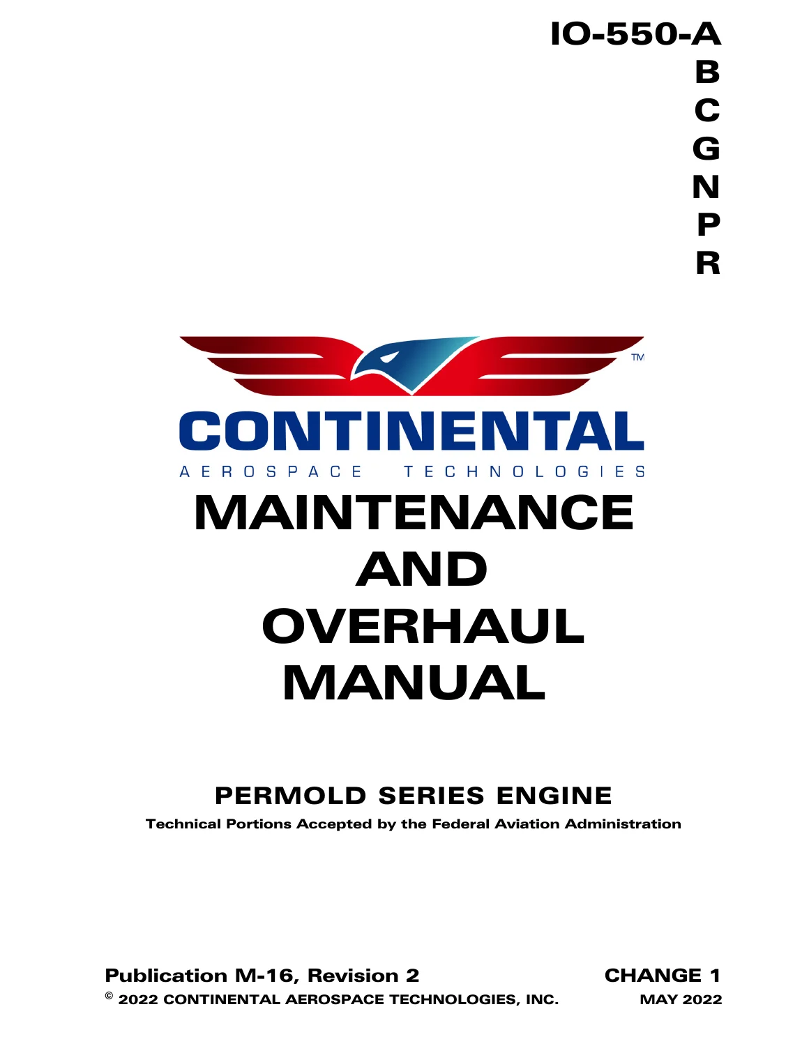
Continental IO-550 Permold Series Engine Maintenance and Overhaul Manual M-16
This is the complete Continental Aerospace Technologies Maintenance and Overhaul Manual M-16 for the IO-550 Permold Series engine family, covering the IO-550-A, IO-550-B, IO-550-C, IO-550-G, IO-550-N, IO-550-P and IO-550-R engine models. The Continental IO-550 Permold Series Engine Maintenance and Overhaul Manual is presented as Revision 2, Change 1, dated May 2022, and was developed as the Instructions for Continued Airworthiness (ICA) for these engines under 14 CFR Part 33, Section 33.4.
- Manual Type: Maintenance and Overhaul Manual (ICA)
- Brand / Family: Continental Aerospace Technologies — IO-550 Permold Series
- Covered Models: IO-550-A, IO-550-B, IO-550-C, IO-550-G, IO-550-N, IO-550-P, IO-550-R
- Language: English
- Page Count: 602 pages
- File Format: PDF
- Publication Number: M-16
- Revision: Revision 2, Change 1
- Publication Date: May 2022 (Change 1); Initial Publication Date 15 October 2021
Chapters Covered
The IO-550 Permold Series Engine Maintenance and Overhaul Manual is organized into 18 chapters plus appendices, taking a technician from engine familiarization through full teardown and rebuild:
- Chapter 1 — Introduction: scope, effectivity symbols, advisories, publication access and change distribution, service documents
- Chapter 2 — Engine Description: engine model number definition, cylinder numbering, crankcase, drive train, crankshaft, connecting rods, camshaft, cylinders, pistons, hydraulic tappets, lubrication system, engine cooling, induction and exhaust systems, and the Table 2-2 through Table 2-9 engine specification tables
- Chapter 3 — Special Tools and Supplies
- Chapter 4 — Airworthiness Limitations
- Chapter 5 — Engine Removal and Installation: aircraft and engine preparation, installation sequence, fuel injection system purge, preflight and run-up, and IO-550-A/B/C/G/N/P/R installation drawings
- Chapter 6 — Engine Inspection and Service: scheduled inspection items, induction/cylinder drain inspection, exhaust system inspection, Hartzell (Kelly) alternator inspection, unscheduled maintenance (propeller strike, hydraulic lock, overspeed, lightning strike, contaminated fuel, foreign object contamination), inspection checklists
- Chapter 7 — Engine Operation
- Chapter 8 — Troubleshooting: fuel injection, charging, starting, ignition, lubrication, cylinder, crankcase and exhaust system fault topics
- Chapter 9 — Engine Preservation and Storage: preservation checklist, new/unused engine storage, temporary and indefinite storage of installed and crated engines
- Chapter 10 — Non-Overhaul Repair: magneto installation, accessory drive adapter replacement, oil filter adapter stud replacement, oil pump/tachometer drive repair, oil sump and suction tube repair, oil cooler repair, oil pressure relief valve repair, oil temperature control valve inspection, rocker arm and hydraulic tappet removal, cylinder maintenance, and component service limits
- Chapter 11 — Engine Overhaul Introduction: overhaul sequence, removal and disassembly checklist, visual/fluorescent penetrant/magnetic particle/ultrasonic/dimensional inspection checklists, cylinder and drive train inspection checklists, replacement parts inventory
- Chapter 12 — Engine Disassembly: accessory drive adapter removal, fuel injection system removal by model, induction system removal, exhaust system removal, oil cooler removal
- Chapter 13 — Component Disassembly: starter and adapter disassembly, engine cylinder disassembly, accessory drive pad disassembly, crankcase disassembly, engine drive train disassembly (camshaft, crankshaft, counterweights), compressor mounting kit disassembly
- Chapter 14 — Engine Cleaning
- Chapter 15 — Overhaul Inspection and Repair: engine overhaul inspection, overhaul repair procedures for the fuel injection, induction, alternator, starter/starter adapter, ignition, exhaust and lubrication systems, stud height settings, cylinder repair vs. replacement guidelines, mandatory cylinder overhaul replacement parts, engine drive train parts replacement
- Chapter 16 — Component Assembly: fuel injection system, alternator, starter and starter adapter, exhaust system, lubrication system (oil pump, oil cooler), engine cylinder assembly
- Chapter 17 — Engine Assembly: crankcase hardware, hydraulic valve tappet and pushrod installation, rocker arm installation, cylinder drain tube and baffle installation, oil sump and suction tube installation, oil pump installation, accessory drive pad installation, starter and starter adapter installation, induction, fuel injection, oil cooler and alternator installation by model
- Chapter 18 — Post-Overhaul Test and Engine Operation Prerequisites
- Appendices A through D — including Appendix D overhaul dimensions and service limits for the fuel injection system, starter and starter adapter, ignition system, lubrication system, engine cylinder overhaul dimensions, crankcase, engine drive train, crankshaft counterweight assemblies, connecting rod dimensions, and detailed stud height setting tables and figures for each crankcase part number
Complete PDF Bookmark Tree
Complete Bookmarks
The complete bookmarks in the “Continental IO-550 Permold Series Engine Maintenance and Overhaul Manual M-16” are as follows:
+Chapter 1 . Introductionp. 27
+1-1. Scope and Purpose of This Manualp. 27
1-1.1. Instructions for Continued Airworthinessp. 27
1-1.2. Effectivity Symbolsp. 27
1-1.3. Advisoriesp. 28
+1-1.4. Using this Manualp. 28
Figure 1-1. Figure and Index Referencep. 29
1-1.5. Compliancep. 30
1-1.6. Order of Precedencep. 31
+1-2. Publicationsp. 31
1-2.1. Publication Accessp. 31
1-2.2. Publication Changesp. 31
+1-2.3. Update/Change Distributionp. 32
Figure 1-2. Change Page Identificationp. 32
Figure 1-3. List of Effective Pagesp. 33
+1-2.4. Service Documentsp. 34
1-2.4.1. Service Documents Incorporated in this Manualp. 35
1-2.4.2. Service Documents Released after Publicationp. 38
+1-2.5. Related Publicationsp. 40
Table 1-1. Related Publicationsp. 40
1-2.5.1. Suggestions and Correctionsp. 40
1-3. Contact Informationp. 41
+Chapter 2 . Engine Descriptionp. 43
+2-1. General Engine Descriptionp. 43
+2-1.1. Engine Model Number Definitionp. 44
Figure 2-1. Engine Model Definitionp. 44
+2-1.2. Cylinder Number Designationsp. 44
Figure 2-2. Cylinder Number Designationp. 44
+2-2. Detailed Engine Descriptionp. 45
+2-2.1. Crankcasep. 45
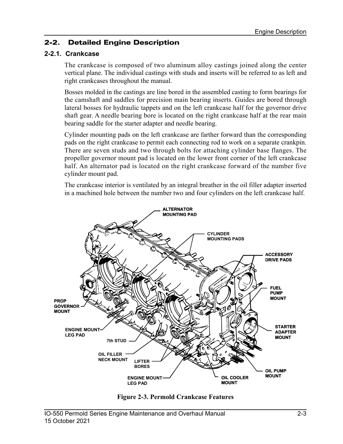
Figure 2-3. Permold Crankcase Featuresp. 45
+2-2.2. Engine Drive Trainp. 46
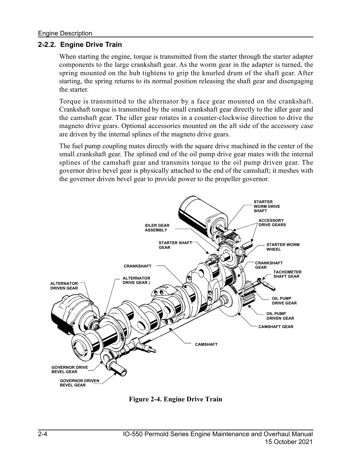
Figure 2-4. Engine Drive Trainp. 46
+2-2.2.1. Crankshaftp. 47
Figure 2-5. Crankshaftp. 47
+2-2.2.2. Connecting Rodsp. 47
Figure 2-6. Connecting Rodp. 48
+2-2.2.3. Camshaftp. 48
Figure 2-7. Camshaftp. 48
2-2.2.4. Idler Gearp. 49
+2-2.3. Cylindersp. 49
2-2.3.1. Updraft Cylinder Designp. 49
+2-2.3.2. Cross-flow Cylinder Designp. 49
Figure 2-8. Updraft Cylinder Featuresp. 50
Figure 2-9. Crossflow Cylinder Featuresp. 50
+2-2.3.3. Pistonsp. 51
Figure 2-10. Piston Featuresp. 51
2-2.3.4. Hydraulic Valve Tappetsp. 51
+2-2.4. Lubrication Systemp. 51
Figure 2-11. Lubrication Schematicp. 52
+2-2.4.1. Oil Pumpp. 52
Figure 2-12. Oil Pumpp. 53
2-2.4.2. Oil Sumpsp. 53
+2-2.4.3. Oil Cooler and Oil Temperature Control Valvep. 54
Figure 2-13. Oil Coolerp. 54
+2-2.5. Fuel Systemp. 55
Figure 2-14. IO-550-G, N, P & R Fuel System Schematicp. 55
Figure 2-15. IO-550-A, B & C Fuel System Schematicp. 55
+2-2.5.1. Fuel Pumpp. 56
Table 2-1. Legend for Figure 2-16p. 56
Figure 2-16. IO-550 Fuel Pump Fittings and Adjustmentsp. 57
+2-2.5.2. Fuel Injectorsp. 58
Figure 2-17. IO-550-A, B & C Fuel Injector Nozzlep. 58
Figure 2-18. IO-550-G, N, P & R Fuel Injector Nozzlep. 58
+2-2.6. Starter Assemblyp. 59
Figure 2-19. Starting Systemp. 59
2-2.7. Alternatorp. 59
+2-2.8. Ignition Systemp. 60
Figure 2-20. Continental Magneto Part Number Definitionp. 60
Figure 2-21. Continental Ignition System Schematicp. 61
Figure 2-22. Champion Slick Ignition System Schematicp. 61
+2-2.9. Engine Coolingp. 62
Figure 2-23. Engine Coolingp. 62
+2-2.10. Induction Systemp. 62
Figure 2-24. Typical Updraft Induction Systemp. 63
Figure 2-25. Typical Cross-flow Induction Systemp. 63
2-2.11. Exhaust Systemp. 64
+2-3. Engine Specificationsp. 64
Table 2-2. IO-550 Series Engine Characteristicsp. 64
Table 2-3. IO-550 Performance Specificationsp. 65
Table 2-4. IO-550 Lubrication System Specificationsp. 66
Table 2-5. IO-550 Fuel System Specificationsp. 67
Table 2-6. Fuel Consumptionp. 67
Table 2-7. Engine Physical Specificationsp. 68
+2-3.1. IO-550-Accessory Drive Ratiosp. 69
Table 2-8. Accessory Drive Ratiosp. 69
2-3.1.1. Accessory Drive Padp. 69
2-3.2. Oil Specificationsp. 69
+2-3.3. Propellerp. 69
Table 2-9. Propeller Moment of Inertiap. 69
+2-3.4. Performance Datap. 70
+2-3.4.1. IO-550-A Performance Chartsp. 71
Figure 2-26. IO-550-A Fuel Flow vs. Brake Horsepowerp. 71
Figure 2-27. IO-550-A Sea Level Performancep. 72
+2-3.4.2. IO-550-B Performance Chartsp. 73
Figure 2-28. IO-550-B Fuel Flow vs. Brake Horsepowerp. 73
Figure 2-29. IO-550-B Sea Level Performancep. 74
+2-3.4.3. IO-550-C Performance Chartsp. 75
Figure 2-30. IO-550-C Fuel Flow vs. Brake Horsepowerp. 75
Figure 2-31. IO-550-C Sea Level Performancep. 76
+2-3.4.4. IO-550-G Performance Chartsp. 77
Figure 2-32. IO-550-G Fuel Flow vs. Brake Horsepowerp. 77
Figure 2-33. IO-550-G Sea Level Performancep. 78
+2-3.4.5. IO-550-N, P & R Performance Chartsp. 79
Figure 2-34. IO-550-N, P & R Fuel Flow vs. Brake Horsepowerp. 79
Figure 2-35. IO-550-N, P & R Sea Level Performancep. 80
+Chapter 3 . Special Tools and Suppliesp. 81
+3-1. Special Toolsp. 81
3-1.1. Vendor Contact Informationp. 81
3-1.2. Mechanic’s Toolsp. 81
+3-2. Lubricants, Sealants and Adhesivesp. 82
3-2.1. Engine Oil Specificationsp. 82
3-2.2. Recommended Oil Grade:p. 82
3-2.3. Recommended Ashless Dispersant Aviation Engine Oilsp. 82
3-2.4. Oil Change Intervalsp. 82
3-2.5. Additivesp. 82
3-2.6. Sealantsp. 82
3-2.7. Lubricantsp. 82
3-2.8. Adhesivesp. 82
3-2.9. Miscellaneousp. 82
+Chapter 4 . Airworthiness Limitationsp. 83
4-1. Mandatory Replacement Timesp. 83
4-2. Mandatory Inspection Intervalsp. 83
4-3. Other Related Proceduresp. 83
4-4. Distribution of Changes to Airworthiness Limitationsp. 83
+Chapter 5 . Engine Removal and Installationp. 85
5-1. Engine Removalp. 85
+5-2. Engine Installationp. 87
5-2.1. Materials Requiredp. 87
5-2.2. Engine Receipt and Handlingp. 87
5-2.3. Uncrating the Enginep. 87
5-2.4. Crating an Engine for Shippingp. 88
5-2.5. Acceptance Inspectionp. 88
5-2.6. Engine Transportp. 88
+5-3. Installation Proceduresp. 89
5-3.1. Prepare the Aircraft for Engine Installationp. 89
5-3.2. Prepare the Engine for Installationp. 89
5-3.3. Installation Sequencep. 91
5-3.4. Fuel Injection System Purgep. 92
5-3.5. Installation Inspectionp. 93
+5-3.6. Preflight and Run-upp. 94
5-3.6.1. Post Ground Run Inspectionp. 95
+5-4. Engine Installation Drawingsp. 96
+5-4.1. IO-550 Common Installation Drawingsp. 96
Figure 5-1. Exhaust Port Dimensionsp. 96
Figure 5-2. Propeller Flange Dimensionsp. 97
Figure 5-3. Gear Driven Alternator Detailp. 98
Figure 5-4. Gear Driven Alternator Detail, cont.p. 99
Figure 5-5. Belt Driven Alternator Detailp. 99
+5-4.2. IO-550-A Engine Installation Drawings
Figure 5-6. IO-550-A Installation Drawing 641029 – Sheet 1 of 2
Figure 5-7. IO-550-A Installation Drawing 641029 – Sheet 2 of 2p. 102
+5-4.3. IO-550-B Engine Installation Drawings
Figure 5-8. IO-550-B Installation Drawing 646608 – Sheet 1 of 2
Figure 5-9. IO-550-B Installation Drawing 646608 – Sheet 2 of 2p. 104
+5-4.4. IO-550-C Engine Installation Drawings
Figure 5-10. IO-550-C Installation Drawing 646616 – Sheet 1 of 2p. 105
Figure 5-11. IO-550-C Installation Drawing 646616 – Sheet 2 of 2p. 106
+5-4.5. IO-550-G Engine Installation Drawings
Figure 5-12. IO-550-G & N Installation Drawing 652180 – Sheet 1 of 2p. 107
Figure 5-13. IO-550-G & N Installation Drawing 652180 – Sheet 2 of 2p. 108
+5-4.6. IO-550-N Engine Installation Drawings
Figure 5-14. IO-550-N Installation Drawing 656924 – Sheet 1 of 3p. 109
Figure 5-15. IO-550-N Installation Drawing 656924 – Sheet 2 of 3p. 110
Figure 5-16. IO-550-N Installation Drawing 656924 – Sheet 3 of 3p. 111
+5-4.7. IO-550-P Engine Installation Drawings
Figure 5-17. IO-550-P Installation Drawing 654576 – Sheet 1 of 2p. 112
Figure 5-18. IO-550-P Installation Drawing 654576 – Sheet 2 of 2p. 113
+5-4.8. IO-550-R Engine Installation Drawings
Figure 5-19. IO-550-R Installation Drawing 655575 – Sheet 1 of 2p. 114
Figure 5-20. IO-550-R Installation Drawing 655575 – Sheet 2 of 2p. 115
+Chapter 6 . Engine Inspection and Servicep. 117
6-1. Inspection Program Introductionp. 117
6-2. Inspection and Maintenance Schedulep. 117
+6-3. Scheduled Inspectionsp. 118
Table 6-1. Engine Inspection and Maintenance Schedulep. 118
6-3.1. One Time Post – Installation Inspectionsp. 118
6-3.2. 25-Hour Initial Operation Inspectionp. 119
6-3.3. 50-Hour Engine Inspectionp. 119
6-3.4. 100-Hour (Annual) Engine Inspectionp. 120
6-3.5. 500-Hour Engine Inspectionp. 120
6-3.6. Visual Inspectionp. 120
+6-3.7. Engine Operational Checkp. 120
6-3.7.1. Oil Pump Operational Checkp. 120
6-3.7.2. Fuel System Operational Checkp. 120
6-3.7.3. Magneto RPM Drop Checkp. 120
6-3.8. Engine Oil Servicingp. 121
+6-3.9. Ignition System Maintenancep. 121
Figure 6-1. Champion (Slick) Ignition Harness Routingp. 121
Figure 6-2. Continental Ignition Harness Routingp. 122
+6-3.10. Engine Adjustmentsp. 123
+6-3.10.1. Belt Tension Check and Adjustmentp. 123
6-3.10.1.1. Air Conditioning Compressor Drive Belt Tension Check and Adjustmentp. 123
6-3.10.1.2. 70 Amp Alternator Drive Belt Tension Check and Adjustmentp. 123
6-3.11. Cylinder Inspectionsp. 124
+6-3.12. Crankcase Inspectionp. 124
+6-3.12.1. Crankcase Inspection with Refrigerant Compressorp. 124
Figure 6-3. Mount Boss with Thick Ribp. 124
Figure 6-4. Mount Boss with Thin Ribp. 124
Figure 6-5. General Inspection Areap. 125
Figure 6-6. Suspect Crack Indicationp. 126
6-3.13. Engine Mount Inspectionp. 127
6-3.14. Induction System Inspectionp. 127
6-3.15. Ignition System Inspectionp. 127
6-3.16. Engine Gauge Inspectionp. 127
6-3.17. Fuel System Inspectionp. 127
6-3.18. Throttle and Mixture Control Lever Inspectionp. 127
6-3.19. Engine Control Linkage Inspectionp. 127
6-3.20. Induction or Cylinder Drain Inspectionp. 127
6-3.21. Exhaust System Inspectionp. 127
+6-3.22. Alternator Inspectionp. 128
+6-3.22.1. Hartzell (Kelly) ES10024 Series Alternator Inspectionp. 128
Figure 6-7. ES10024 Alternatorp. 129
+6-3.22.2. Hartzell (Kelly) ES7024 Belt Driven Alternator Inspectionp. 130
Figure 6-8. ES7024 Alternator Assemblyp. 130
+6-4. Unscheduled Maintenancep. 132
+6-4.1. Propeller Strikep. 132
6-4.1.1. Propeller Strike Inspectionp. 132
6-4.2. Hydraulic Lock Inspectionp. 132
6-4.3. Engine Overspeed Inspectionsp. 132
6-4.4. Lightning Strike Inspectionp. 132
6-4.5. Contaminated Fuel System Inspectionp. 132
6-4.6. Foreign Object Contamination Inspectionp. 132
6-5. Inspection Checklistsp. 132
+Chapter 7 . Engine Operationp. 133
7-1. Introductionp. 133
+7-2. Flight Prerequisitesp. 133
7-2.1. Oil Change Intervalp. 133
7-2.2. Engine Fuel Requirementsp. 134
+7-2.3. Flight Check and Break-Inp. 135
7-2.3.1. Engine Break-Inp. 135
7-2.3.2. Flight Checkp. 135
+7-3. Normal Operationp. 136
7-3.1. Pre-operational Requirementsp. 136
+7-3.2. Engine Startp. 137
7-3.2.1. Cold Startp. 138
7-3.2.2. Flooded Enginep. 138
7-3.2.3. Hot Startp. 139
7-3.3. Ground Run-upp. 139
7-3.4. Engine Shutdownp. 141
+7-4. Engine Operation in Abnormal Environmentsp. 142
7-4.1. Engine Operation in Extreme Coldp. 142
+7-4.2. Engine Operation in Hot Weatherp. 142
7-4.2.1. Cooling an Engine in Hot Weatherp. 143
7-4.2.2. Engine Restart in Hot Weatherp. 143
7-4.3. Ground Operation at High Density Altitudep. 143
+Chapter 8 . Troubleshootingp. 145
+8-1. General Troubleshootingp. 146
8-1.1. Engine Runs Roughp. 146
8-1.2. Engine Will Not Runp. 146
8-1.3. Engine Indication Malfunctionsp. 146
8-1.4. Engine Performance Malfunctionsp. 146
8-2. Induction Systemp. 146
8-3. Fuel Injection Systemp. 146
8-4. Charging Systemp. 146
8-5. Starting Systemp. 146
8-6. Ignition Systemp. 146
8-7. Lubrication Systemp. 147
8-8. Engine Cylindersp. 147
+8-9. Crankcasep. 147
8-9.1. Excess Crankcase Pressurep. 147
8-10. Exhaust Systemp. 147
+Chapter 9 . Engine Preservation and Storagep. 149
+9-1. Preserving and Storing an Enginep. 149
9-1.1. Engine Preservation Checklistp. 149
9-1.2. New or Unused Engine Storagep. 149
9-1.3. Installed Engine, Temporary Storagep. 149
9-1.4. Installed Engine, Indefinite Storagep. 149
9-1.5. Crated Engine, Indefinite Storagep. 149
9-1.6. Return an Engine to Service after Storagep. 149
9-2. Turbocharger Preservation and Storagep. 149
+Chapter 10 . Non-Overhaul Repair and Replacementp. 151
+10-1. Parts Replacementp. 151
Table 10-1. Non-Overhaul Parts Replacement Referencep. 152
Table 10-2. Parts Repair Referencep. 153
Table 10-3. Parts Handling Guidelinesp. 153
+10-2. Fuel Pump Replacementp. 154
+10-2.1. Fuel Pump Removalp. 154
Figure 10-1. IO-550 Fuel Pump Adjustments & Fittingsp. 155
+10-2.2. Fuel Pump Service Limitsp. 156
Figure 10-2. Fuel Pump Drive Coupling Fits and Limitsp. 156
Table 10-4. Fuel Pump Drive Coupling Dimensionsp. 156
+10-2.3. Fuel Pump Installationp. 156
Figure 10-3. Fuel Pump Assemblyp. 157
+10-3. Fuel Injector Replacementp. 158
Figure 10-4. Fuel Injector Assembliesp. 159
+10-4. Starter Motor and Adapter Replacementp. 160
10-4.1. Starter Motor Removalp. 160
+10-4.2. Starter Adapter Removalp. 160
Figure 10-5. Starter Motor and Starter Adapterp. 161
+10-4.3. Starter and Starter Adapter Service Limitsp. 162
Table 10-5. Basic Starter Adapter Dimensionsp. 162
Figure 10-6. Basic Starter Adapterp. 163
Figure 10-7. Worm Wheel Drum Dimensionsp. 163
Table 10-6. Worm Wheel Drum Dimensionsp. 163
Figure 10-8. shaftgear Drum Dimensionsp. 164
Table 10-7. Shaftgear Drum Dimensionsp. 164
Table 10-8. Starter Adapter with Accessory Drive Service Limitsp. 164
Figure 10-9. Starter Adapter with Scavenge Pumpp. 165
10-4.4. Starter Adapter Installationp. 166
10-4.5. Starter Motor Installationp. 166
+10-5. Alternator Replacementp. 168
+10-5.1. Belt Driven Alternator Replacement Instructionsp. 168
+10-5.1.1. 70 Amp Belt Driven Alternator Removalp. 168
Figure 10-10. 70 Amp Belt Driven Alternator Bracket Assemblyp. 169
10-5.1.2. 70 Amp Belt Driven Alternator Installationp. 169
+10-6. Magneto Replacementp. 172
10-6.1. Continental Magneto Removalp. 172
10-6.2. Champion (Slick) Magneto Removalp. 172
+10-6.3. Ignition System Service Limitsp. 173
Table 10-9. Ignition System Service Limitsp. 173
Figure 10-11. Accessory Drive Adapter Dimensionsp. 174
10-6.4. Continental Magneto Installationp. 175
10-6.5. Champion (Slick) Magneto Installationp. 175
+10-6.6. Accessory Drive Adapter Replacementp. 176
Figure 10-12. Accessory Drive Assemblyp. 177
+10-7. Lubrication System Repairp. 178
10-7.1. Oil Filter Adapter Stud Replacementp. 178
10-7.2. Oil Pump or Tachometer Drive Repair and Replacementp. 178
10-7.3. Oil Sump and Oil Suction Tube Repair and Replacementp. 179
10-7.4. Oil Cooler Repair and Replacementp. 179
+10-7.5. Oil Pressure Relief Valve Repair and Replacementp. 180
Figure 10-13. Rear View of Enginep. 180
Figure 10-14. Oil Pressure Relief Valvep. 181
Figure 10-15. Valve Seat in the Oil Pump Housingp. 181
+10-7.6. Oil Temperature Control Valve Inspection and Replacementp. 182
Figure 10-16. Oil Temperature Control Valvep. 182
+10-7.7. Lubrication Component Service Limitsp. 184
Table 10-10. Lubrication System Component Service Limitsp. 184
Figure 10-17. Lubrication System Service Limitsp. 185
+10-8. Engine Cylinder Maintenancep. 186
+10-8.1. IO-550-A, B & C Rocker Arm Removalp. 186
Figure 10-18. Updraft Cylinder Assemblyp. 187
+10-8.2. IO-550-G, N, P & R Rocker Arm Removalp. 188
Figure 10-19. Crossflow Cylinder Assemblyp. 189
+10-8.3. Updraft Cylinder Hydraulic Tappet Removalp. 190
Figure 10-20. Updraft Cylinder Pushrod Tube Assemblyp. 191
+10-8.4. Crossflow Cylinder Hydraulic Tappet Removalp. 192
Figure 10-21. Crossflow Cylinder Pushrod Tube Assemblyp. 193
+10-8.5. IO-550-A, B & C Cylinder Removalp. 194
Figure 10-22. Packing Installed to Stabilize Connecting Rodsp. 195
Figure 10-23. Piston, Piston Pin and Piston Ringsp. 196
Figure 10-24. Static Sealp. 197
10-8.6. IO-550 G, N, P & R Engine Cylinder Removalp. 198
+10-8.7. Engine Cylinder Dimensional Inspectionp. 201
Figure 10-25. Pushrod Dimensionsp. 203
+10-8.7.1. IO-550-A, B & C Series Engines Cylinders Service Limitsp. 205
Table 10-11. IO-550-A, B & C Cylinder Assembly Service Limitsp. 205
Figure 10-26. IO-550-A, B & C Cylinder Assemblyp. 206
+10-8.7.2. IO-550-G, N, P & R Cylinder Service Limitsp. 207
Table 10-12. IO-550-G, N, P & R Cylinder Assembly Service Limitsp. 207
Figure 10-27. IO-550-G, N, P & R Cylinder Assembly Service Limitsp. 209
Figure 10-28. Intake Valve Seat Dimensionsp. 210
Figure 10-29. Exhaust Valve Seat Dimensionsp. 210
Figure 10-30. Valve Service Limitsp. 211
10-8.8. IO-550-A, B & C Engine Cylinder Installationp. 212
10-8.9. IO-550-G, N, P & R Cylinder Installationp. 216
+10-8.10. Cylinder Torquep. 220
Figure 10-31. Single Cylinder Torque Sequencep. 221
+10-8.11. Updraft Cylinder Hydraulic Tappet Installationp. 222
Figure 10-32. Pushrod Spring Compressorp. 223
10-8.12. Crossflow Cylinder Hydraulic Tappet Installationp. 224
+10-8.13. Updraft Cylinder Rocker Arm Installationp. 226
Figure 10-33. Updraft Cylinder Rocker Arm Side Clearancep. 226
Figure 10-34. Rocker Arm to Retainer Clearancep. 227
+10-8.14. Crossflow Cylinder Rocker Arm Installationp. 228
Figure 10-35. Rocker Arm Side Clearancep. 229
10-9. Crankshaft Nose Oil Seal Replacementp. 230
10-10. Crankcase Repairp. 230
10-11. Exhaust System Repairsp. 230
10-12. Engine Preservation and Storagep. 230
+Chapter 11 . Engine Overhaul Introductionp. 231
11-1. Engine Overhaulp. 231
11-2. Overhaul Schedulep. 231
+11-3. Overhaul Sequencep. 232
Table 11-1. Overhaul Sequencep. 232
+11-4. Overhaul Checklistsp. 232
Table 11-2. Engine Removal and Disassembly Checklistp. 234
Table 11-3. Engine Overhaul Visual Inspection Checklistp. 235
Table 11-4. Fluorescent Penetrant Inspection Checklistp. 242
Table 11-5. Magnetic Particle Inspection Checklistp. 244
Table 11-6. Ultrasonic Inspection Checklistp. 245
Table 11-7. Dimensional Inspection Checklistp. 246
Table 11-8. Engine Cylinder Overhaul Inspection Checklistp. 255
Table 11-9. Engine Drive Train Inspection Checklistp. 256
Table 11-10. Replacement Parts Inventoryp. 258
+Chapter 12 . Engine Disassemblyp. 261
12-1. Engine Disassembly Sequencep. 261
+12-2. Ignition System Removal and Disassemblyp. 262
+12-2.1. Continental Ignition System Removalp. 262
Figure 12-1. Magneto Tachometer Sensorp. 262
Figure 12-2. Continental Ignition Systemp. 263
+12-2.2. Champion (Slick) Ignition System Removalp. 264
Figure 12-3. Champion (Slick) Ignition Systemp. 264
+12-3. Accessory Drive Adapter Removalp. 265
Figure 12-4. Accessory Drive Adapter Assemblyp. 265
+12-4. Fuel Injection System Removalp. 266
+12-4.1. IO-550-A Fuel Injection System Removalp. 266
Figure 12-5. IO-550-A Fuel Injection Assemblyp. 267
+12-4.2. IO-550-B Fuel Injection System Removalp. 268
Figure 12-6. IO-550-B Fuel Injection Assemblyp. 269
+12-4.3. IO-550-C Fuel Injection System Removalp. 270
Figure 12-7. IO-550-C Fuel Injection Assemblyp. 271
+12-4.4. IO-550 G, N, P, R Fuel Injection System Removalp. 272
Figure 12-8. IO-550-G, N, P, & R Fuel Injection Assemblyp. 273
Figure 12-9. IO-550-G, N, P & R Throttle and Metering Assemblyp. 274
+12-5. Induction System Removalp. 276
+12-5.1. IO-550-A Induction System Removalp. 276
Figure 12-10. IO-550-A Induction Assemblyp. 277
+12-5.2. IO-550-B Induction System Removalp. 278
Figure 12-11. IO-550-B Induction Assemblyp. 278
+12-5.3. IO-550-C Induction System Removalp. 279
Figure 12-12. IO-550-C Induction Assemblyp. 279
+12-5.4. IO-550-G, N, P, & R Induction System Removalp. 280
Figure 12-13. IO-550-G, N, P, & R Induction Assemblyp. 281
12-6. Exhaust System Removalp. 282
+12-7. Oil Cooler Removalp. 282
+12-7.1. Oil Cooler Removalp. 282
Figure 12-14. IO-550-A & B Oil Coolerp. 283
+12-7.2. Oil Cooler Removalp. 284
Figure 12-15. IO-550-C Oil Coolerp. 285
+12-7.3. Oil Cooler Removalp. 286
Figure 12-16. IO-550-G, N, P & R Oil Coolerp. 287
+12-7.4. Oil Cooler Removalp. 288
Figure 12-17. IO-550-N Oil Coolerp. 289
+12-8. Oil Pump Removalp. 290
Figure 12-18. Oil Pump Assemblyp. 291
+12-9. Alternator Removalp. 292
+12-9.1. Belt Driven Alternator Removalp. 293
Figure 12-19. Belt Driven Alternator Bracket Assemblyp. 293
+12-9.2. Belt Driven Alternator Bracket and Drive Sheave Removalp. 294
Figure 12-20. Optional Alternator Bracket Assemblyp. 294
+12-10. Compressor Mounting Assembly (Optional) Removalp. 295
Figure 12-21. Optional Refrigerant Compressor Mount Assemblyp. 295
+12-11. Starter and Adapter Removalp. 296
Figure 12-22. Starter and Adapterp. 296
+12-12. Oil Sump Removalp. 297
+12-12.1. IO-550-A & C Oil Sump Removalp. 297
Figure 12-23. IO-550-A & C Oil Sumpp. 297
+12-12.2. IO-550-B & R Oil Sump Removalp. 298
Figure 12-24. IO-550-B & R Oil Sumpp. 298
+12-12.3. IO-550-G & N Oil Sump Removalp. 299
Figure 12-25. IO-550-G & N Oil Sumpp. 299
+12-12.4. IO-550-P Oil Sump Removalp. 300
Figure 12-26. IO-550-P Oil Sumpp. 300
+12-13. Engine Cylinder Removalp. 301
+12-13.1. IO-550-A, B & C Engine Cylinder Removalp. 301
Figure 12-27. IO-550-A, B & C Engine Cylinderp. 302
Figure 12-28. Piston Assemblyp. 303
Figure 12-29. Cylinder Base Packing support Connecting Rodsp. 303
+12-13.2. IO-550-G, N, P & R Inter-Cylinder Baffle Removalp. 305
Figure 12-30. Inter-Cylinder Baffle Assemblyp. 306
+12-13.3. IO-550-G, N, P & R Engine Cylinder Removalp. 307
Figure 12-31. Cylinder Drain Tube Fittingp. 307
Figure 12-32. IO-550-G, N, P & R Engine Cylinderp. 308
+12-14. Engine Mount Removalp. 310
+12-14.1. IO-550-A Engine Mount Removalp. 310
Figure 12-33. IO-550-A Engine Mountsp. 310
+12-14.2. IO-550-C Engine Mount Removalp. 311
Figure 12-34. IO-550-C Engine Mountsp. 311
+12-14.3. IO-550-G, N & P Engine Mount Removalp. 312
Figure 12-35. IO-550-G, N & P Engine Mountsp. 312
+Chapter 13 . Component Disassemblyp. 313
13-1. Ignition Systemp. 313
+13-2. Fuel Injection Systemp. 314
Figure 13-1. Fitting Orientation Guidep. 314
+13-3. Oil Pump Disassemblyp. 315
+13-3.1. Standard Oil Pump Disassemblyp. 316
Figure 13-2. Standard Oil Pumpp. 317
+13-3.2. Oil Pump with Mechanical Tachometer Drive Adapter Disassemblyp. 318
Figure 13-3. Oil Pump Assembly with Mechanical Tachometer Drive Adapterp. 319
+13-3.3. Oil Pump with Electrical Tachometer Drive Adapter Disassemblyp. 320
Figure 13-4. Oil Pump Assembly with Electrical Tachometer Drive Adapterp. 321
+13-4. Starter and Adapter Disassemblyp. 322
+13-4.1. Basic Starter and Starter Adapter Disassemblyp. 323
Figure 13-5. Starter and Adapterp. 324
+13-4.2. Starter Adapter with Accessory Drive Disassemblyp. 325
Figure 13-6. Starter and Adapter with Accessory Drivep. 326
+13-5. Engine Cylinder Disassemblyp. 329
+13-5.1. IO-550-A, B, & C Engine Cylinder Disassemblyp. 329
Figure 13-7. IO-550-A, B & C Cylinder Assemblyp. 330
+13-5.2. IO-550-G, N, P & R Cylinder Disassemblyp. 331
Figure 13-8. IO-550-G, N, P & R Cylinder Assemblyp. 332
+13-6. Accessory Drive Pad Disassemblyp. 333
Figure 13-9. Accessory Drive Assemblyp. 333
+13-7. Crankcase Disassemblyp. 334
+13-7.1. Miscellaneous Crankcase Accessory Removalp. 334
Figure 13-10. Miscellaneous Crankcase Hardwarep. 334
Figure 13-11. Crankcase Fastener Locationsp. 335
13-7.2. Crankcase Studding Disassemblyp. 337
+13-8. Engine Drive Train Disassemblyp. 338
+13-8.1. Camshaft Disassemblyp. 338
Figure 13-12. Keyed Camshaftp. 338
Figure 13-13. Camshaft Assemblyp. 339
+13-8.2. Crankshaft Disassemblyp. 340
Figure 13-14. Crankshaft Assemblyp. 341
13-8.2.1. Crankshaft Counterweight Removalp. 342
+13-9. Compressor Mounting Kit Disassemblyp. 342
Figure 13-15. Refrigerant Compressor Mounting Kitp. 343
Chapter 14 . Engine Cleaningp. 345
+Chapter 15 . Overhaul Inspection and Repairp. 347
15-1. Engine Overhaul Inspectionp. 347
15-2. Engine Overhaul Inspection Checklistsp. 347
+15-3. Visual Inspectionp. 347
15-3.1. Gear Tooth Inspectionp. 347
15-4. Fluorescent Penetrant Inspectionp. 347
+15-5. Magnetic Particle Inspectionp. 347
15-5.1. Connecting Rod Magnetic Particle Inspectionp. 347
+15-6. Ultrasonic Inspectionsp. 348
15-6.1. Crankshaft Ultrasonic Inspectionp. 348
+15-7. Dimensional Inspectionp. 349
+15-7.1. Crankcase Dimensional Inspectionp. 350
Figure 15-1. Crankcase Dimensional Inspection Torque Sequencep. 351
+15-7.2. Drive Train Dimensional Inspectionp. 352
Figure 15-2. Crankshaft Journalsp. 352
15-7.2.1. Connecting Rod Dimensional Inspectionp. 353
15-7.2.2. Crankshaft Counterweight Inspectionp. 353
15-7.2.3. Crankshaft Counterweight Bushing Bore Inspectionp. 353
+15-7.2.4. Crankshaft Dowel Dimensional Inspectionp. 353
Figure 15-3. Crankshaft Dowelp. 353
15-7.3. Engine Cylinder Dimensional Inspectionp. 354
15-7.4. Starter Adapter Dimensional Inspectionp. 355
15-7.5. Lubrication System Dimensional Inspectionp. 355
15-7.6. Alternator Drive Hub Slippage Inspectionp. 356
15-7.7. Throttle and Mixture Control Lever Inspectionp. 356
15-7.8. Exhaust System Inspectionp. 357
15-7.9. Accessory Drive Adapter Dimensional Inspectionp. 357
+15-7.10. Stud Height Dimensional Inspectionp. 357
Table 15-1. Stud Height Settingsp. 357
+15-7.11. Refrigerant Compressor Dimensional Inspectionp. 358
Figure 15-4. Refrigerant Compressor Sheavep. 358
+15-8. Overhaul Repairp. 359
15-8.1. Fuel Injection System Overhaul Repairp. 359
+15-8.2. Induction System Overhaul Repairp. 359
+15-8.2.1. IO-550-G, N, P & R Induction Manifold Overhaul Repairp. 360
Figure 15-5. Induction Manifold Fittingsp. 360
15-8.3. Refrigerant Compressor Mount Overhaul Repairp. 360
15-8.4. Alternator Overhaulp. 361
+15-8.5. Starter and Starter Adapter Overhaul Repairp. 361
+15-8.5.1. Starter Adapter Housing Worm Shaft Needle Bearing Replacementp. 362
Figure 15-6. Starter and Adapter with Accessory Drivep. 362
+15-8.6. Ignition System Overhaulp. 362
+15-8.6.1. Accessory Drive Adapter Overhaulp. 362
Figure 15-7. Accessory Drive Adapter Bushing Installation Detailp. 363
15-8.7. Exhaust System Overhaul Repairp. 364
+15-8.8. Lubrication System Overhaulp. 364
15-8.8.1. Oil Cooler Overhaul Repairp. 364
+15-8.8.2. Oil Pressure Relief Valve Seat Repairp. 365
Figure 15-8. Oil Pressure Relief Valvep. 365
15-8.8.3. Oil Filter Adapter Stud Replacementp. 365
15-8.8.4. Tachometer Drive Assembly Replacementp. 365
+15-8.9. Engine Cylinder Overhaul Repairp. 366
+15-8.9.1. Cylinder Repair versus Replacement Guidelinesp. 367
Table 15-2. Cylinder Repair vs. Replacement Guidelinesp. 367
+15-8.9.2. Engine Overhaul Replacement Partsp. 368
Table 15-3. Mandatory Cylinder Overhaul Replacement Partsp. 368
+15-8.9.3. Rocker Shaft Retention Modificationp. 368
Figure 15-9. M92-6 Compliance Stampp. 368
Figure 15-10. Part No. 8181 Drill Guidep. 369
+15-8.9.4. New Cylinder Position Numbersp. 370
Figure 15-11. Cylinder Position Numberp. 370
15-8.9.5. Cylinder Head Repairp. 370
15-8.9.6. Cylinder Fin Tip Repairp. 371
15-8.9.7. Cylinder Barrel Repairp. 371
15-8.9.8. Cylinder Bore Honingp. 372
15-8.9.9. Valve Seat Removalp. 373
15-8.9.10. Valve Seat Installationp. 374
15-8.9.11. Valve Guide Removalp. 375
15-8.9.12. Valve Guide Installationp. 376
15-8.9.13. Valve Guide Bore Reamingp. 377
15-8.9.14. Valve Seat Machiningp. 377
15-8.9.15. Spark Plug Helical Coil Insert Replacementp. 378
15-8.9.16. Cylinder Stud Installationp. 379
15-8.9.17. Piston Ring Replacementp. 379
15-8.9.18. Cylinder Protective Coatingsp. 379
+15-8.9.19. Rocker Arm Bushing Replacementp. 380
+15-8.9.19.1. Rocker Arm (Dual) Bushing Replacementp. 380
Figure 15-12. Rocker Arm Bushing (Dual Bushing Type) Replacementp. 381
+15-8.9.19.2. Rocker Arm (Single) Bushing Replacementp. 382
Figure 15-13. Rocker Arm Single Bushing Replacementp. 383
+15-8.9.20. Rocker Arm-to-Retainer Clearancep. 384
Figure 15-14. Rocker Arm to Retainer Clearancep. 384
15-8.10. Inter-Cylinder Baffle Repairp. 385
+15-8.11. Crankcase Overhaul Repairp. 385
+15-8.11.1. Camshaft Gear Replacementp. 386
Figure 15-15. Radius Cut Distance from Camshaft Centerlinep. 386
Figure 15-16. Overhead View of Radius Cut Depthp. 386
15-8.11.2. Crankcase Line Boringp. 387
15-8.11.3. Crankcase Machiningp. 387
15-8.11.4. Crankcase Weldingp. 387
15-8.11.5. Oil Filler Overhaul Repairp. 387
+15-8.11.6. Crankcase Cylinder Deck Stud Helical Coil Installationp. 388
Figure 15-17. Cylinder Deck Stud Helical Coil Repair Instructionsp. 388
15-8.11.7. Crankcase Cylinder Deck Stud Replacementp. 389
+15-8.12. Engine Drive Train Overhaulp. 390
Table 15-4. Engine Drive Train Parts Replacementp. 390
15-8.12.1. Camshaft Repairp. 391
15-8.12.2. Crankshaft Repairp. 392
+15-8.12.3. Crankshaft Dowel Replacementp. 393
15-8.12.3.1. Oil Control Plug Replacementp. 394
15-8.12.3.2. Crankshaft Counterweight Bushing Replacementp. 394
15-8.12.3.3. Crankshaft Hanger Blade Bushing Replacementp. 394
15-8.12.3.4. Crankshaft Plating Overhaulp. 394
15-8.12.3.5. Connecting Rod Replacementp. 394
+Chapter 16 . Component Assemblyp. 395
+16-1. Fuel Injection Systemp. 395
16-1.1. Fuel Injection System Component Assemblyp. 395
16-1.2. Fuel Injector Nozzlesp. 395
16-2. Alternator Assemblyp. 396
+16-3. Starter & Starter Adapter Assemblyp. 397
+16-3.1. Starter & Starter Adapter with Scavenge Pump Assemblyp. 398
Figure 16-1. Worm Wheel Gear Installation Toolp. 398
Figure 16-2. Starter with Accessory Drivep. 399
Figure 16-3. Scavenge Pump Housing Silk Thread Patternp. 401
Figure 16-4. Starter w/Accessory Drive Adapter Oil Seal Positionp. 402
Figure 16-5. Oil Seal Retainer Clip Positionp. 403
+16-3.2. Basic Starter & Starter Adapter Assemblyp. 404
Figure 16-6. Basic Starter and Starter Adapter Assemblyp. 405
16-4. Exhaust System Assemblyp. 407
+16-5. Lubrication System Assemblyp. 408
+16-5.1. Oil Pump Assemblyp. 408
+16-5.1.1. Basic Oil Pump Assemblyp. 408
Figure 16-7. Oil Pump Housing Silk Thread Patternp. 408
Figure 16-8. Oil Pump Assemblyp. 409
+16-5.1.2. Oil Pump Assembly w/Mechanical Tach Drive Adapterp. 410
Figure 16-9. Oil Pump with Mechanical Tach Drive Assemblyp. 411
+16-5.1.3. Oil Pump with Electric Tach Drive Adapter Assemblyp. 412
Figure 16-10. Oil Pump Assembly with Electrical Tach Drive Adapterp. 413
16-5.2. Oil Cooler Assemblyp. 414
+16-6. Engine Cylinder Assemblyp. 414
16-6.1. Cylinder Component Preparationp. 414
+16-6.2. Cylinder Baffle Installationp. 415
Figure 16-11. Cylinder Baffle Installationp. 415
Figure 16-12. Secure Baffle with Springp. 415
+16-6.3. Piston Ring Gap Adjustmentp. 416
Figure 16-13. Piston Ring Installation Orderp. 416
Figure 16-14. Pistons, Piston Rings and Piston Pin Assemblyp. 417
+16-6.4. Valve Train Installationp. 418
Figure 16-15. Updraft Cylinder Assemblyp. 419
Figure 16-16. Crossflow Cylinder Assemblyp. 419
Figure 16-17. Valve and Spring Installationp. 420
+16-6.5. Cylinder Component Assemblyp. 421
Figure 16-18. Updraft Cylinder Pushrod Tube Assemblyp. 421
Figure 16-19. Crossflow Cylinder Pushrod Tube Assemblyp. 421
+16-7. Crankcase Assemblyp. 422
+16-7.1. Oil Filler Installationp. 423
Figure 16-20. Miscellaneous Crankcase Hardwarep. 423
+16-8. Engine Mount Installationp. 424
+16-8.1. IO-550-A Engine Mount Installationp. 424
Figure 16-21. IO-550-A Engine Mounting Bracketsp. 424
+16-8.2. IO-550-C Engine Mount Installationp. 425
Figure 16-22. IO-550-C Engine Mounting Bracketsp. 425
+16-8.3. IO-550-G, N & P Engine Mount Installationp. 426
Figure 16-23. IO-550-G, N & P Engine Mounting Bracketsp. 426
+16-9. Engine Drive Train Assemblyp. 427
+16-9.1. Camshaft Assemblyp. 427
Figure 16-24. Camshaft Assemblyp. 427
+16-9.2. Crankshaft Assemblyp. 428
Figure 16-25. Crankshaft Assemblyp. 429
+16-10. Compressor Mounting Kit Assemblyp. 430
Figure 16-26. Refrigerant Compressor Mounting Assemblyp. 431
+Chapter 17 . Engine Assemblyp. 433
+17-1. Engine Assembly Sequencep. 433
17-1.1. Component Lubricationp. 433
+17-2. Crankcase Assemblyp. 434
+17-2.1. Drive Train Installationp. 434
Figure 17-1. Crankshaft Assemblyp. 435
Figure 17-2. Camshaft Assemblyp. 436
Figure 17-3. Timing Mark Alignmentp. 437
Figure 17-4. Oil Filler, Support Pin, and Camshaft Coverp. 438
Figure 17-5. Left Crankcase Assembled on Standp. 439
Figure 17-6. Cylinder Base O-ring supporting the Connecting Rodsp. 440
+17-2.2. Crankcase Hardware Installationp. 441
+17-2.2.1. IO-550-A, B & C Crankcase Assemblyp. 441
Figure 17-7. Crankcase Fastener Locationsp. 441
Figure 17-8. Permold Crankcase Fastenersp. 442
17-2.2.2. IO-550-G, N, P & R Crankcase Assemblyp. 443
+17-3. Cylinder Installationp. 445
+17-3.1. IO-550-A, B & C Cylinder Installationp. 445
Figure 17-9. Piston, Piston Rings & Piston Pinp. 446
Figure 17-10. Updraft Cylinder Assemblyp. 447
+17-3.2. IO-550-G, N, P & R Cylinder Installationp. 448
Figure 17-11. Crossflow Cylinder Assemblyp. 449
+17-3.3. Cylinder and Crankcase Torquep. 450
Figure 17-12. Permold Crankcase Torque Sequencep. 451
+17-3.4. Crankcase Miscellaneous Hardware Installationp. 452
Figure 17-13. Miscellaneous Crankcase Fastenersp. 453
+17-3.5. Hydraulic Valve Tappet and Pushrod Installationp. 454
+17-3.5.1. IO-550-A, B & C Valve Tappet and Pushrod Installationp. 454
Figure 17-14. Pushrod Housing Installationp. 454
17-3.5.2. IO-550-G, N, P & R Valve Tappet and Pushrod Installationp. 456
+17-3.6. Rocker Arm Installationp. 458
+17-3.6.1. IO-550-A, B & C Rocker Arm Installationp. 458
Figure 17-15. Updraft Cylinder Rocker Arm Side Clearancep. 458
Figure 17-16. Rocker Arm to Retainer Clearancep. 459
+17-3.6.2. IO-550-G, N, P & R Rocker Arm Installationp. 460
Figure 17-17. Crossflow Cylinder Rocker Arm Side Clearancep. 460
17-3.7. Cylinder Drain Tube Installationp. 462
+17-3.8. Inter-Cylinder Baffle Installationp. 464
Figure 17-18. Inter-Cylinder Baffle Assemblyp. 465
+17-4. Oil Sump & Suction Tube Installationp. 466
Figure 17-19. Oil Sump Torque Sequencep. 466
+17-4.1. IO-550-A & C Oil Suction Tube & Sump Installationp. 466
Figure 17-20. IO-550-A & C Oil Sumpp. 467
+17-4.2. IO-550-B & R Oil Suction Tube & Sump Installationp. 468
Figure 17-21. IO-550-B & R Oil Sump Assemblyp. 469
+17-4.3. IO-550-G & N Oil Suction Tube & Sump Installationp. 470
Figure 17-22. IO-550-G & N Oil Sump Assemblyp. 471
+17-4.4. IO-550-P Oil Sump Installationp. 472
Figure 17-23. IO-550-P Oil Sump Assemblyp. 473
+17-5. Oil Pump Installationp. 474
Figure 17-24. Oil Pump Assemblyp. 475
+17-6. Accessory Drive Pad Installationp. 476
Figure 17-25. IO-550-C Throttle Support Bracketp. 476
Figure 17-26. Accessory Drive Adapter Assemblyp. 477
+17-7. Starter and Starter Adapter Installationp. 478
Figure 17-27. Starter and Adapter Assemblyp. 478
+17-8. Oil Cooler Installationp. 479
+17-8.1. IO-550-A & B Oil Cooler Installationp. 480
Figure 17-28. IO-550-A & B Oil Cooler Assemblyp. 481
+17-8.2. IO-550-C Oil Cooler Installationp. 482
Figure 17-29. IO-550-C Oil Coolerp. 483
+17-8.3. IO-550-G, N, P & R Oil Cooler Installationp. 484
Figure 17-30. IO-550-G, N, P & R Oil Cooler Assemblyp. 485
+17-8.4. IO-550-N Oil Cooler Installationp. 486
Figure 17-31. IO-550-N Oil Coolerp. 487
+17-9. Alternator Installationp. 488
17-9.1. Direct Drive Alternator Installationp. 488
+17-9.2. 70 Amp Belt Driven Alternator Assembly Installationp. 489
Figure 17-32. 70 Amp Belt-Driven Alternator Assembly (Optional)p. 490
Figure 17-33. Alternator Brace Shim Locationp. 491
+17-10. Induction System Installationp. 492
+17-10.1. IO-550-A Induction System Installationp. 492
Figure 17-34. IO-550-A Induction Assemblyp. 493
+17-10.2. IO-550-B Induction System Installationp. 494
Figure 17-35. IO-550-B Induction Assemblyp. 495
+17-10.3. IO-550-C Induction System Installationp. 496
Figure 17-36. IO-550-C Induction Assemblyp. 497
+17-10.4. IO-550-G, N, P & R Induction System Installationp. 498
Figure 17-37. IO-550-G, N, P & R Induction Assemblyp. 499
+17-11. Fuel Injection System Installationp. 500
+17-11.1. IO-550-A Fuel Injection System Installationp. 500
Figure 17-38. Anti-Seize Applicationp. 500
Figure 17-39. IO-550-A Fuel Injection Assemblyp. 501
+17-11.2. IO-550-B Fuel Injection System Installationp. 502
Figure 17-40. IO-550-B Fuel Injection Assemblyp. 503
+17-11.3. IO-550-C Fuel Injection System Installationp. 506
Figure 17-41. IO-550-C Fuel Injection Assemblyp. 507
+17-11.4. IO-550-G, N, P & R Fuel Injection System Installationp. 510
Figure 17-42. IO-550-G, N, P & R Fuel Injection Assemblyp. 511
+17-12. Compressor (Optional) Mount Installationp. 514
Figure 17-43. Refrigerant Compressor Mounting Assemblyp. 515
Figure 17-44. Starter Adapter Belt Sheave Alignmentp. 516
Figure 17-45. Sheave Alignmentp. 517
Figure 17-46. Belt Tension Adjustmentp. 518
+17-13. Ignition System Installationp. 519
17-13.1. Continental Ignition System Installationp. 519
17-13.2. Champion (Slick) Ignition System Installationp. 519
+Chapter 18 . Post-Overhaul Test and Adjustmentsp. 521
+18-1. Introductionp. 521
Table 18-1. Engine Operation Prerequisitesp. 521
18-2. Post-Overhaul Testing Prerequisitesp. 521
18-3. Post-Overhaul Test Operating Limitsp. 523
+18-4. Standard Acceptance Testp. 524
Table 18-2. Standard Acceptance Test Requirementsp. 524
+18-5. Oil Consumption Testp. 525
Table 18-3. Oil Consumption Test Requirementsp. 525
18-6. Drive Belt Tension Checkp. 525
+Appendix A . Glossaryp. 527
A-1. Acronymsp. 527
A-2. Terms and Definitionsp. 527
Appendix B . Torque Specificationsp. 529
+Appendix C . Standard Practicesp. 531
C-1. Handling Partsp. 531
+C-2. Replacement Partsp. 531
C-2.1. Backgroundp. 531
+C-2.2. Acceptable Replacement Partsp. 531
C-2.2.1. Know Your Supplierp. 531
C-2.3. 100% Parts Replacement Requirementsp. 531
C-2.4. Mandatory Overhaul Replacement Partsp. 531
C-2.5. Authorized Oversize/Undersize Partsp. 531
C-3. Safety Wiring Hardwarep. 531
C-4. Tab Washer Installationp. 531
+C-5. Heli-Coil® Insert Replacementp. 531
C-5.1. Heli-Coil® Removalp. 531
C-5.2. Heli-Coil® Insertionp. 531
+C-6. Stud Replacementp. 531
+C-6.1. Stud Removalp. 531
C-6.1.1. Size-on-Size Rosan® Stud Removalp. 532
+C-6.1.2. Step-Type Rosan® Stud Removalp. 532
C-6.1.2.1. Step-Type Rosan® Stud Removal Method 1p. 532
C-6.1.2.2. Step Type Rosan Stud Removal Method 2p. 532
+C-6.2. Stud Installationp. 532
C-6.2.1. Rosan® Stud Installationp. 532
C-7. Cotter Pin Installationp. 532
+C-8. Fuel System Servicep. 532
C-8.1. Fuel System Purgep. 532
C-9. Gasket Maker® Applicationp. 532
C-10. Gasket Installationp. 532
C-11. Hose and Tubing Installationp. 532
C-12. Harness Routingp. 532
+Appendix D . Overhaul Dimensional Limitsp. 533
D-1. Overhaul Dimensional Limits=New Part Dimensionsp. 533
+D-2. Fuel Injection Systemp. 534
Figure D-1. Fuel Pump Drive Coupling Fits & Limitsp. 534
Table D-1. Fuel Pump Drive Coupling Dimensionsp. 534
D-2.1. Throttle and Mixture Control Leverp. 535
+D-3. Starter and Starter Adapterp. 536
Figure D-2. Basic Starter Adapterp. 536
Table D-2. Basic Starter Adapter Overhaul Dimensionsp. 537
Figure D-3. Worm Wheel Drum Dimensionsp. 538
Table D-3. Worm Wheel Drum Dimensionsp. 538
Figure D-4. Shaft Gear Drum Dimensionsp. 539
Table D-4. Shaft Gear Drum Fits & Limitsp. 539
Table D-5. Starter/Starter Adapter with Scavenge Pump Dimensionsp. 540
Figure D-5. Starter and Starter Adapter with Scavenge Pump Dimensionsp. 541
+D-4. Ignition Systemp. 542
Table D-6. Ignition System Dimensionalp. 542
Figure D-6. Accessory Drive Adapter Dimensionsp. 542
+D-5. Lubrication Systemp. 543
Table D-7. Lubrication System Dimensionsp. 543
Table D-8. Lubrication System Components Dimensionsp. 544
Figure D-7. Oil Pump Dimensionsp. 544
+D-6. Engine Cylinder Overhaul Dimensionsp. 545
Table D-9. Cylinder Assembly Dimensionsp. 545
Figure D-8. IO-550-A, B & C Updraft Cylinder Dimensionsp. 546
Table D-10. Updraft Engine Cylinder Assembly Dimensionsp. 547
Figure D-9. Crossflow Cylinder Assembly Dimensionsp. 549
Table D-11. Crossflow Cylinder Assembly Dimensionsp. 550
Table D-12. Cylinder Assembly Dimensionsp. 551
Figure D-10. Intake Valve Seat Dimensionsp. 552
Figure D-11. Exhaust Valve Seat Dimensionsp. 553
Figure D-12. Intake Valve Dimensionsp. 554
Figure D-13. Exhaust Valve Dimensionsp. 554
+D-7. Crankcasep. 555
Table D-13. Additional Crankcase Dimensionsp. 555
Figure D-14. Crankcase Main Bearing Oil Feed Hole Chamferp. 555
Figure D-15. Crankcase Dimensionsp. 556
Table D-14. Crankcase Dimensionsp. 556
+D-8. Engine Drive Trainp. 557
Table D-15. Additional Engine Drive Train Dimensionsp. 557
Figure D-16. Engine Drive Train Dimensionsp. 558
Table D-16. Engine Drive Train Dimensionsp. 558
Figure D-17. Crankshaft, Camshaft, and Idler Gear Backlashp. 560
Table D-17. Crankshaft, Camshaft, and Idler Gear Backlashp. 560
Figure D-18. Pushrod Dimensionsp. 560
D-8.1. Crankshaft Counterweight Assembliesp. 561
D-8.2. Counterweight Pinsp. 561
D-8.3. Crankshaft Hanger Blade and Counterweight Bushing Dimensionsp. 561
D-8.4. Connecting Rod Dimensionsp. 561
+D-9. Stud Height Settingsp. 562
+D-9.1. Starter Adapter Stud Height Settingsp. 562
Figure D-19. Basic Starter Adapter Studsp. 562
Table D-18. Basic Starter Adapter Stud Heightsp. 562
Figure D-20. Starter Adapter with Accessory Drive Studsp. 563
Table D-19. Starter Adapter with Accessory Drive Stud Heightsp. 563
+D-9.2. Lubrication System Stud Height Settingsp. 564
Figure D-21. Lubrication System Stud Height Settingsp. 564
Figure D-22. IO-550-B & -R Oil Sump Stud Height Settingp. 564
+D-9.3. Accessory Drive Adapter Stud Heightp. 565
Figure D-23. Accessory Drive Adapterp. 565
+D-9.4. Cylinder Stud Height Settingsp. 566
Figure D-24. Cylinder Stud Heightsp. 566
Table D-20. Cylinder Stud Heightsp. 566
+D-9.5. Oil Control Collar Stud Height Settingsp. 567
Figure D-25. Oil Control Collar Stud Height Settingsp. 567
+D-9.6. Crankcase Plugs and Fittingsp. 567
Table D-21. Crankcase Plugsp. 567
+D-9.7. Crankcase Stud Height Settingsp. 568
Table D-22. 658673-1 & -5 Crankcase Stud Heightsp. 568
Figure D-26. 658673-1 through -8 Crankcase Stud Detailp. 569
Table D-23. 658673-2 and -6 Crankcase Stud Heightsp. 570
Table D-24. 658673-3 Crankcase Stud Heightsp. 572
Table D-25. 656619-4 Crankcase Stud Heightsp. 574
Table D-26. 658673-7 Crankcase Stud Heightsp. 576
Table D-27. 658673-8 Crankcase Stud Heightsp. 578
Table D-28. 658673-9 Crankcase Stud Heightsp. 580
Figure D-27. 658673-9 Crankcase Stud Detailp. 581
Table D-29. 656673-28 Crankcase Stud Heightsp. 582
Figure D-28. 658673-11, -12, -13, -14, -26 & -28 Crankcase Stud Detailp. 583
Table D-30. 658673-11 Crankcase Stud Heightsp. 584
Table D-31. 658673-12 Crankcase Stud Heightsp. 586
Table D-32. 658673-13 Crankcase Stud Heightsp. 588
Table D-33. 658673-14 Crankcase Stud Heightsp. 590
Table D-34. 658673-26 Crankcase Stud Heightsp. 592
Figure D-29. 656619-15, -17 & -24 Crankcase Stud Detailp. 593
Table D-35. 658673-16 Crankcase Stud Heightsp. 594
Figure D-30. 658673-16 & -18 Crankcase Stud Detailp. 595
Table D-36. 658673-27 Crankcase Stud Heightsp. 596
Table D-37. 658673-18 Crankcase Stud Heightsp. 598
Together these chapters give a technician everything needed to service a Permold Series IO-550 engine from the flight line through a complete bench overhaul — scheduled inspections and troubleshooting on one end, and full disassembly, cleaning, dimensional inspection, repair, reassembly and post-overhaul test on the other.
Engine Coverage and Specifications
The Continental IO-550 Permold Series Engine Maintenance and Overhaul Manual documents six-cylinder, fuel-injected, horizontally opposed, air-cooled engines built around the Permold crankcase casting, with a 5.25 in. bore and 4.25 in. stroke giving 550 cubic inches of displacement and an 8.5:1 compression ratio. The IO-550-A, B and C models use an updraft cylinder design, while the IO-550-G, N, P and R models use a crossflow cylinder design with inclined valves. The manual details FAA Type Certificate E3S0, installation drawing numbers for each model, magneto types and timing, spark plug references, exhaust back-pressure limits, and cylinder head temperature limits, along with rated and cruise horsepower figures, oil pressure/temperature limits and sump capacities, fuel system specifications, and dry weight/overall dimension data for every listed model.
Why Technicians and Owners Rely on This Manual
This Continental IO-550 Permold Series Engine Maintenance and Overhaul Manual gives a mechanic the ability to perform correct scheduled inspections, diagnose starting, charging, ignition, fuel and lubrication system faults, carry out non-overhaul repairs on components such as oil coolers, oil pumps, magnetos and starter adapters, and — when the time comes — remove, disassemble, clean, inspect, repair, reassemble and test-run a complete engine overhaul in line with the manufacturer’s Instructions for Continued Airworthiness. Because procedures, torque values, service limits and replacement-parts requirements are specific to the Permold Series IO-550-A/B/C/G/N/P/R family, working from this manual rather than a generic reference helps ensure the work is done to the correct specification. The Continental IO-550 Permold Series Engine Maintenance and Overhaul Manual downloads instantly as a PDF after purchase — no shipping wait, no physical copy to misplace — and can be read on a laptop, tablet, or phone in the hangar or printed for the shop floor.
Reviews
There are no reviews yet.