
Chevrolet CV Series Electrical Circuit Diagram Manual – Complete Wiring Schematics PDF
Original price was: $39.95.$24.95Current price is: $24.95.
Full electrical circuit diagram manual for the Chevrolet CV Series, covering power and ground distribution, GMLAN and MOST data communication, body builder provisions, cab and chassis accessories, engine systems, HVAC, lighting, transmission, harness routing and every connector end view.
Description
Chevrolet CV Series Electrical Circuit Diagram Manual
The Chevrolet CV Series Electrical Circuit Diagram Manual is the complete electrical schematic set for the CV Series truck, laid out page by page the way an electrical technician actually works. It follows every circuit from the underhood power distribution module through the instrument panel fuse blocks, out into the cab, the doors, the chassis and the rear of the vehicle, and finishes with the harness routing views, the master electrical component list and the full connector end views. If a fuse keeps blowing, a module will not communicate, a body builder upfit has no power, or a ground is suspect, this is the document that shows you where the wire goes and what it feeds.
File Details
- Manual type: Electrical circuit diagram / wiring schematic manual
- Model coverage: CV Series
- Language: English
- Page count: 1,175 pages
- File format: PDF, instant download
- Structure: 17 numbered sections plus two appendices
- Appendix A: Feature code table (RPO descriptions)
- Appendix B: Naming convention and acronyms table
Chapters Covered
- How to Use This Manual – electrical schematic symbols, general icons, switch position icons, module circuit function icons, harness components, component parts, switches and relays, devices and sensors, vehicle zoning strategy
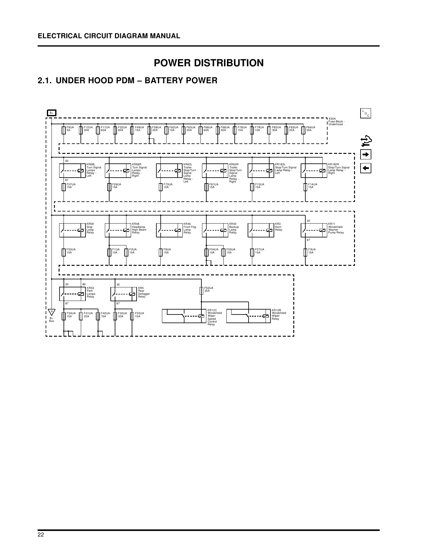
- Power Distribution – under hood PDM battery power, under hood PDM ignition power, instrument panel left PDM battery, ignition and accessory power, instrument panel right PDM battery and retained accessory power, ignition switch, 12 volt system
- Ground Distribution – cab, center chassis, driver side door, passenger side door, instrument panel, module splice pack, splice packs, rear chassis, under hood PDM
- Data Communication – data link power and ground and low speed GMLAN, gateway isolated low speed GMLAN, high speed GMLAN, gateway isolated high speed GMLAN, chassis expansion high speed GMLAN, powertrain expansion bus high speed GMLAN, MOST, MOST communication enable, accessory wakeup and communications enable, linear interconnect network
- Body Builder Provision – emergency vehicle prewire, body builder provision, master disconnect switch, roof beacon, cargo light, stop / turn / backup lights
- Cab Accessories – auxiliary power, radio and navigation, antenna, speakers, radio auxiliary input, radio communication, CD player, window switch, power windows and locks, power door locks, safety restraint system indicators, air bag and seat belt pretensioner wiring, side impact and side curtain airbags, theft deterrent system, windshield wiper system, heated seat switch and grid, key fob locks, exterior rearview mirror, driver and passenger seat adjustment, steering wheel controls
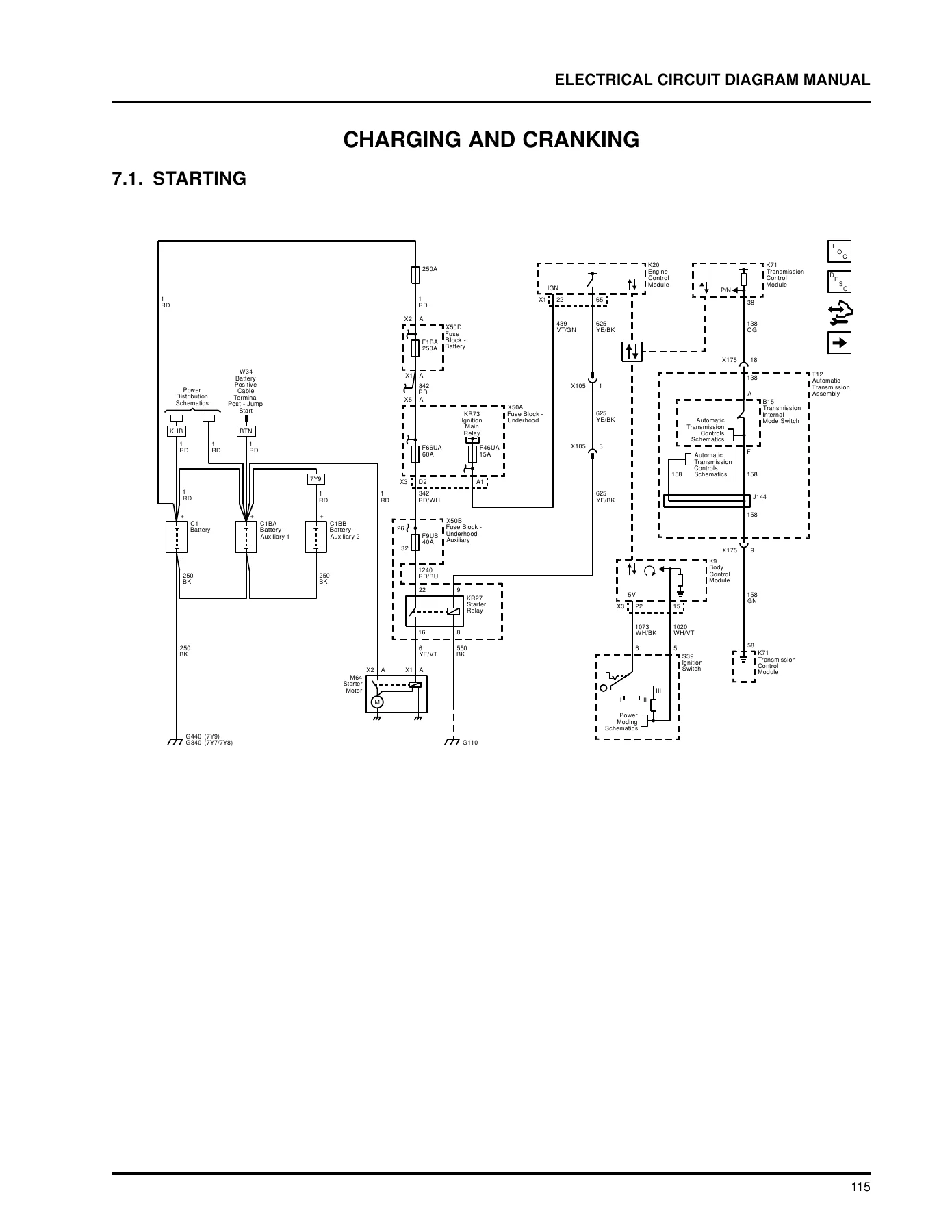
- Charging and Cranking – starting, charging
- Chassis Accessories – antilock brakes, low air pressure indicator, air suspension dump valve, trailer power, trailer lighting, trailer brake controls, rearview camera, air dryer valve heater, hood switch, city horn, window defrost and exterior heated mirrors, hydraulic brake, immobilizer, body control module
- Engine Systems – aftertreatment, glow plugs, fuel pump single tank, fuel system, fuel system dual tank, engine control module, engine controls, cruise control, exhaust brake, cooling fan
- Gauges and Warnings – gauge cluster, steering wheel switches, warning lights, BCM interface, back up alarm
- HVAC – unit actuators, auxiliary heater, compressor and refrigerant sensors, controls
- Lighting System – driver and passenger side park and marker lights, park / marker lighting, cargo lights, tail lights, center high mounted stop light, exterior rearview mirrors, clearance lights, interior lighting, interior lighting dimming, exterior lighting switches, head light assembly, fog lights
- Transfer Case – transfer case control
- Transmission – transmission control module, power take-off, shift lock control
- Harness Routing and Component Locations – harness routing views, master electrical component list, component locator views, ground views, electrical center identification views
- Connector End Views – in-line harness connector end views, splice pack connector end views, component connector end views
- Appendices – feature code table, naming convention and acronyms table
What the Schematics Actually Give You
This is not a general electrical guide. Every page is a circuit diagram drawn for this vehicle, with the fuse block callouts, relay identifications, connector references such as X50A, X51L, X51R and X61A, splice pack numbers, wire colours, circuit numbers, terminal sizes and the zone callouts that tell you where in the truck a connector or ground physically sits. The vehicle zoning strategy section explains the numbering system behind those zones, so a connector labelled in the 500 series points you to the driver door, the 600 series to the front passenger door and the 900 series to the end of the frame, which cuts diagnostic time before you have even opened the hood.
Power distribution is broken out module by module rather than lumped into one drawing. Battery power and ignition power are separated for the under hood power distribution module, and the instrument panel left and right fuse blocks each get their own battery, ignition, accessory and retained accessory power diagrams. That separation is exactly what you need when a circuit is live in run but dead in accessory, or when retained accessory power is dropping out early. The 12 volt system and ignition switch diagrams tie the whole supply side together.
Grounds, Data Networks and Communication Faults
Ground distribution is drawn in its own dedicated section and split by physical location: cab, center chassis, driver side door, passenger side door, instrument panel, rear chassis and under hood PDM, plus the module splice packs and the general splice packs. Ground faults are among the hardest electrical problems to chase without a diagram, and having each ground point drawn with its harness and ground number makes it a matter of following the page instead of guessing.
Data communication covers the network side of the vehicle in depth. Low speed GMLAN, high speed GMLAN, gateway isolated versions of both, chassis expansion high speed GMLAN, powertrain expansion bus high speed GMLAN, MOST and MOST communication enable, accessory wakeup and communications enable, and the linear interconnect network all have their own diagrams, with the terminating resistors and gateway module shown in place. When a module drops off the bus, the data link power and ground diagram is usually the first page worth opening.
Body Builder, Upfitter and Trailer Wiring
Because the CV Series is commonly upfitted, the manual treats body builder provision as a first-class system. Emergency vehicle prewire, the configurable body builder provision, master disconnect switch wiring and its indicator provision, roof beacon, cargo light, and the stop / turn / backup light provisions are all documented, along with the body builder connection harness connectors at the frame. Trailer power, trailer lighting and trailer brake controls have their own diagrams, and the trailer brake power control module and chassis control module appear with their connector pinouts. For an upfitter adding a service body, a crane, a beacon or a trailer package, this section tells you which circuits are already available and where to pick them up.
Component Locator, Ground Views and Connector End Views
The back half of the book is what separates a usable electrical manual from a pile of schematics. The master electrical component list gives every component code with its name, feature code where applicable, physical location and a cross-reference to the locator view. Component views follow for the front of vehicle and engine compartment, powertrain, instrument panel and center console, passenger compartment and roof, doors, rear of vehicle and underbody, with ground views and electrical center identification views for the fuse blocks. Then come the connector end views: in-line harness connectors, splice packs and component connectors, each shown with cavity numbering, wire colour, circuit number, terminal type and function.
That combination means you can look up a fault, follow the schematic to a connector, then flip to the end view and probe the correct cavity with the correct terminal test probe instead of back-probing blind.
Engine, Chassis and Cab Systems Covered
Engine systems diagrams cover aftertreatment, glow plugs, single and dual tank fuel systems, the engine control module connectors, engine controls, cruise control, exhaust brake and cooling fan. Chassis coverage includes antilock brakes, low air pressure indicator, air suspension dump valve, air dryer valve heater, city horn, hood switch, hydraulic brake, immobilizer and the body control module connectors. Cab coverage runs through radio and navigation variants, speakers, power windows and locks, air bag and seat belt pretensioner wiring, side impact and side curtain airbags, theft deterrent, wipers, heated seats, mirrors, seat adjustment and steering wheel controls. HVAC, transfer case and transmission sections, including the transmission control module, power take-off and shift lock control, round out the vehicle systems.
Who This Manual Is For
This electrical circuit diagram manual suits the technician diagnosing a fault on a CV Series truck, the shop that wants the correct fuse, relay and connector references before ordering parts, the upfitter planning a body installation, and the owner or fleet maintainer who would rather trace a circuit properly than replace parts until something works. The feature code table in Appendix A is particularly useful, because it maps the build codes used throughout the schematics to plain descriptions, so a diagram that lists a feature code can be matched to what is actually fitted on the vehicle.
IMAGES PREVIEW
Instant PDF Delivery
The manual is delivered as a PDF download immediately after purchase, with no shipping and no waiting. It opens on a laptop, tablet or phone, pages can be printed for the workshop and marked up as you work, and the section structure makes it practical to jump straight to the diagram you need rather than paging through the whole book. Correct schematics mean correct diagnosis, fewer replaced parts that were never faulty, and wiring repairs that hold up.

Reviews
There are no reviews yet.