
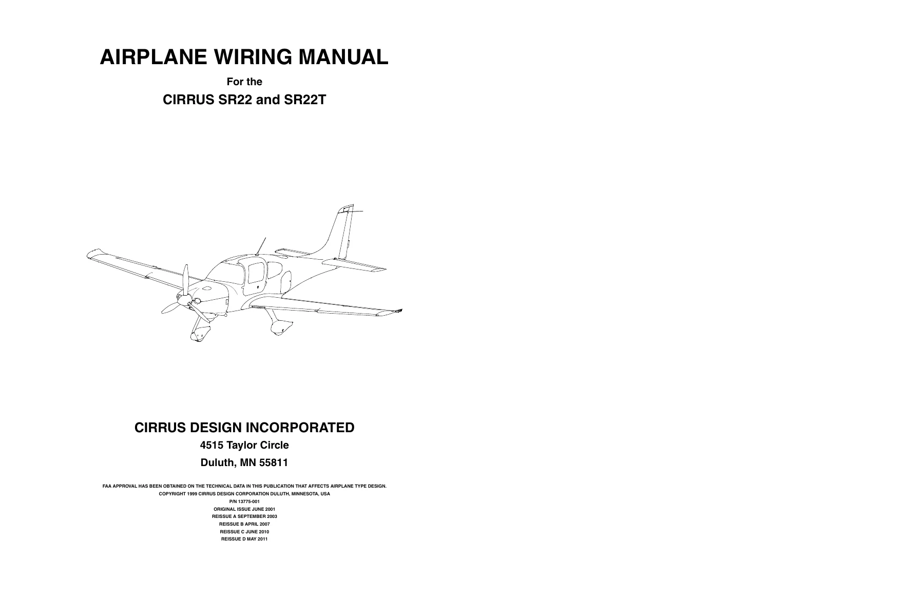
Cirrus SR22 and SR22T Airplane Wiring Manual P/N 13775-001 Rev D4 PDF
Original price was: $44.95.$26.95Current price is: $26.95.
870-page Cirrus SR22 and SR22T airplane wiring manual, P/N 13775-001, Revision D4 dated 01 Jan 2016. Covers serial-effectivity wiring diagrams, electrical troubleshooting and repair practices, system load charts, bus schematics, connector and pin data, switches, relays, avionics, flight controls, electrical power, engine indicating and other aircraft systems.
Description
Cirrus SR22 and SR22T Airplane Wiring Manual P/N 13775-001 Rev D4 PDF
The Cirrus SR22 and SR22T Airplane Wiring Manual P/N 13775-001 Rev D4 PDF provides detailed electrical wiring information for the Cirrus SR22 and SR22T. Prepared by Cirrus Design Technical Publications, this manual is intended to enable a trained mechanic to troubleshoot, test and repair electrical wiring, as well as perform wiring maintenance and minor repairs normally carried out on the flight line or in the maintenance hangar.
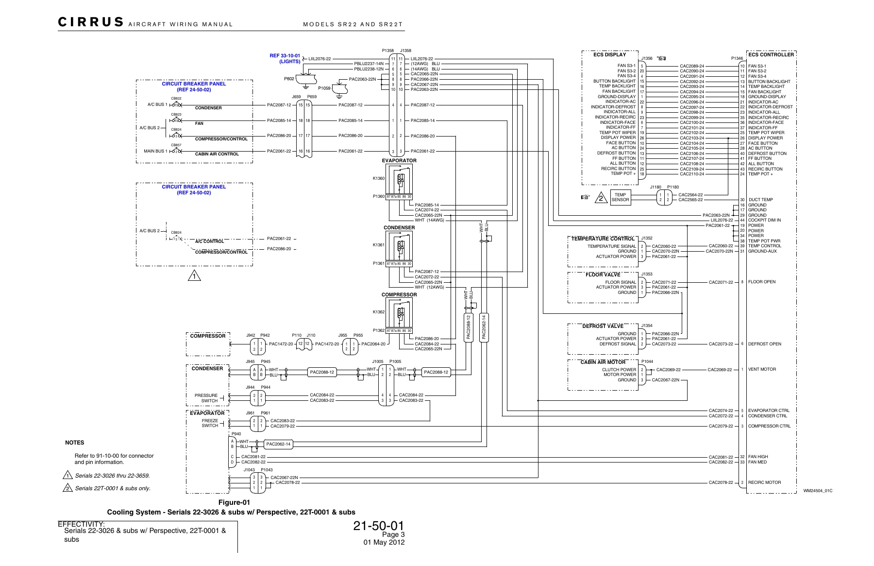
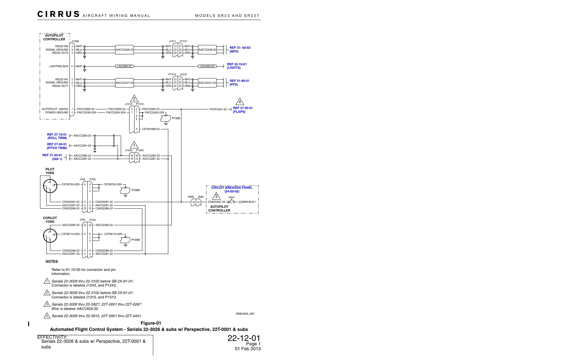
This is a system-by-system electrical reference rather than a general operating manual. Its core content consists of wiring diagrams with aircraft serial-number effectivity, component and connector identification, wire numbers, pin and socket functions, circuit protection, electrical distribution and cross-references between related aircraft systems. The manual also contains hands-on wiring repair practices, electrical load information, bus schematics and extensive connector, switch and relay data.
File Details
- Manual type: Airplane Wiring Manual
- Brand: Cirrus Design
- Models: SR22 and SR22T
- Part number: 13775-001
- Revision: D4
- Revision date: 01 Jan 2016
- Reissue: Reissue D, May 2011
- Original issue: June 2001
- Language: English
- Pages: 870
- File format: PDF
Wiring Diagram Coverage and Effectivity
The Cirrus SR22 and SR22T Airplane Wiring Manual P/N 13775-001 Rev D4 is organized around aircraft groups, chapters and sections in the same general arrangement used by the Airplane Maintenance Manual and Illustrated Parts Catalog. Diagram identifiers use a Chapter-Section-Diagram structure, allowing related wiring information to be traced across systems. References printed inside component boxes or at wire continuations direct the technician to associated diagrams elsewhere in the manual.
Electrical coverage is generally taken to the line replaceable unit level. LRUs are identified on the diagrams and connector pin or socket circuit functions are normally labeled to support troubleshooting, while the internal electrical breakdown of an LRU is generally not shown. The manual also provides connector references that lead to the dedicated connector and pin information section.
Aircraft applicability is important throughout this manual. Each wiring diagram carries its own airplane serial-number effectivity, and applicability can be further affected by avionics configuration, optional equipment and installed Cirrus Design Service Bulletins. The manual contains wiring configurations for numerous equipment arrangements, including conventional and Perspective avionics installations, autopilot configurations, display systems, audio systems, ice-protection installations and other optional equipment shown in the applicable diagrams.
The defined wiring coverage is for the as-delivered airplane configuration and airplanes modified by Cirrus Design Service Bulletins. Wiring changes introduced by other modifications are outside that defined coverage. The introduction also specifically states that information for STC installations is not included and identifies the Tornado Alley Turbo Inc. Turbonormalizer system installed under STC SA10588SC as an example for which the applicable STC Instructions for Continued Airworthiness should be used.
Wiring Repair and Fault Isolation Information
Beyond system schematics, this manual gives technicians practical wiring-maintenance procedures. Chapter 20 explains the wire, cable, harness, plug and jack identification conventions used throughout the aircraft and describes how wire numbers identify systems, circuits, wire gauge and signal information. Fault-isolation guidance covers the use of wiring diagrams during troubleshooting, test-lead procedures and the need to perform the applicable operational checkout or functional test after a malfunction has been cleared.
The wiring repair section covers stripping insulation and shielding, crimping machine pins and sockets, continuous-roll contacts and terminal rings, soldering wires and devices, solder-sleeve splices, heat-shrink devices and wire splicing. It also addresses termination, connectors, coaxial cable, BNC crimp connectors, routing and tying wire bundles, chafing protection, lightning-protection over-braiding, conformal coating of circuit card assemblies and strain relief for discrete LED lamps. These procedures make the SR22 SR22T wiring manual useful not only for tracing circuits but also for carrying out the physical repair work associated with aircraft wiring.
Chapters Covered
- Chapter 20 – Standard Practices: Wiring: wire and cable identification, harness and connector marking, fault isolation, test leads, stripping, crimping, soldering, heat shrink, splicing, terminating, coaxial cable, routing, tying, chafing protection, lightning over-braiding, conformal coating and LED strain relief.
- Chapter 21 – Environmental Systems: cabin air fan assembly, cabin air vent assembly, avionics cooling fan, transponder cooling fan, MFD and PFD cooling fans, and cooling system wiring.
- Chapter 22 – Autoflight: System 30 autopilot and turn coordinator, System 55X autopilot, flight director, automated flight control system and Take-Off/Go-Around switch.
- Chapter 23 – Communications: GDL 88 Universal Access Transceiver and GMA 340, GMA 347 and GMA 350 audio-panel wiring across applicable configurations.
- Chapter 24 – Electrical Power: DC generation, avionics power, circuit breaker panels, convenience power, fluid quantity power and convenience system controller.
- Chapter 25 – Equipment & Furnishings: crew seat harness and emergency locator transmitter installations, including 406 MHz and Artex ELT 1000 configurations.
- Chapter 27 – Flight Controls: roll trim, yaw trim, pitch trim, stall warning and flap control systems.
- Chapter 28 – Fuel: fuel distribution, gascolator and fuel indicating system wiring.
- Chapter 30 – Ice Protection: Basic Ice Protect, Basic2 Ice Protect and FIKI Ice Protect system configurations.
- Chapter 31 – Indicating/Recording Systems: CO detector, hour meter, aircraft data logger, GIA 1 and GIA 2 integrated avionics, annunciator panel, primary flight display, multifunction display and reversionary switch.
- Chapter 32 – Landing Gear: brake temperature sensor and parking brake switch.
- Chapter 33 – Lights: flight compartment, passenger compartment and exterior lighting circuits across applicable aircraft configurations.
- Chapter 34 – Navigation & Pitot Static: pitot heat, clock and OAT gage, air data computers, MD302 standby attitude module, attitude indicator, attitude and heading reference systems, Stormscope, traffic, terrain awareness and warning, GPS, HSI and heading reference, VOR/LOC/GS indication, transponders, ADF, DME, weather and radio systems, Iridium weather, FS210 wireless cockpit transceiver and FMS keypad.
- Chapter 74 – Ignition: engine ignition system wiring.
- Chapter 77 – Engine Indicating: engine indicating circuits and Engine Airframe Unit wiring.
- Chapter 80 – Starting: engine starting and starting-circuit wiring.
- Chapter 91 – System Load Charts and Bus Schematics: circuit load charts, electrical system schematics, power distribution schematics, connector data, switch data and relay data.
- Chapter 93 – Surveillance: Enhanced Vision System wiring.
- Chapter 95 – Special Purpose Equipment: CAPS installation wiring.
- Chapter 115 – Flight Simulator Systems: Cirrus landing gear simulator wiring.
Taken together, these chapters give the technician a broad electrical map of the SR22 and SR22T. The manual follows power generation and distribution into individual aircraft systems, shows connections between avionics and airframe equipment, identifies circuit protection and grounds, and provides configuration-specific diagrams where aircraft evolution changed the wiring. Cross-references between diagrams make it possible to follow a signal or power path from one system chapter into another rather than treating each drawing as an isolated schematic.
Electrical Loads, Bus Schematics and Connector Reference
Chapter 91 adds reference material that is especially useful during electrical diagnosis. The manual includes individual circuit-load charts together with electrical and power-distribution schematics. The introductory material explains that the load analysis represents individual circuit loads and that bus schematics show system current flow during normal operation and circuit-failure conditions.
The same chapter includes dedicated connector, switch and relay data. Connector information provides pin and socket location diagrams together with connector-specific data, while separate identification material is supplied for switches and relays. This supports the frequent diagram references to Section 91-10-00 and gives technicians a central place to confirm connector and pin details while tracing circuits elsewhere in the manual.
Work with the Correct SR22 and SR22T Electrical Data
The Cirrus SR22 and SR22T Airplane Wiring Manual P/N 13775-001 Rev D4 PDF is a practical reference for tracing electrical faults, checking circuit continuity and power paths, identifying connectors and wire numbers, understanding aircraft bus distribution, comparing configuration-specific diagrams and carrying out permitted wiring fabrication or repair procedures. Its serial-effectivity blocks and configuration notes help the technician select the diagram that corresponds to the aircraft being worked on, while the repair practices and connector data provide the supporting information needed once a fault has been located.
Using the correct wiring path, connector identification, circuit protection and applicable effectivity information matters when diagnosing electrical problems or repairing aircraft wiring. After purchase, the manual is supplied as an instant PDF download with no physical shipping required. It can be opened on compatible phones, tablets and computers and printed when a paper reference is useful at the aircraft or workbench.
Reviews
There are no reviews yet.