
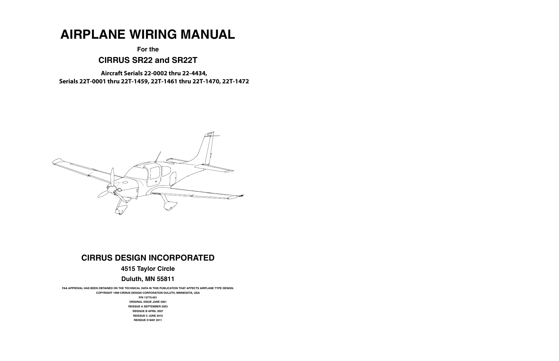
Cirrus SR22 and SR22T Aircraft Wiring Manual (Revision D6)
Original price was: $44.95.$27.95Current price is: $27.95.
Comprehensive factory electrical wiring manual for Cirrus SR22 and SR22T aircraft across serials 22-0002 through 22-4434 and 22T-0001 through 22T-1472. Features line-replaceable unit schematics, GAMA-standard circuit breakdowns, power distribution, harness repair, and avionics pinouts in PDF format.
Description
Cirrus SR22 and SR22T Aircraft Wiring Manual (Revision D6) Overview
The Cirrus SR22 and SR22T Aircraft Wiring Manual (Revision D6) serves as the definitive, FAA-approved technical reference for electrical troubleshooting, line maintenance, system checkout, and wiring harness repair across all production blocks of the Cirrus SR22 and turbocharged SR22T fleet. Prepared directly by Cirrus Design Technical Publications under publication part number 13775-001, this technical publication provides complete circuit schematic coverage to the Line Replaceable Unit (LRU) level. Each diagram details functional LRU connector pinouts, system interconnection logic, terminal terminations, ground studs, and inline splice connections, giving avionics specialists and airframe technicians the granular detail necessary to diagnose intermittent discrepancies, perform component retrofits, and verify continued airworthiness.
File Details
- Document Title: Cirrus SR22 and SR22T Aircraft Wiring Manual
- Publication Part Number: P/N 13775-001
- Revision Level: Revision No. D6 (Dated 04 September 2018; Reissue D dated 31 May 2011)
- Manufacturer: Cirrus Design Corporation / Cirrus Aircraft (Duluth, MN)
- Applicable Aircraft Models: Cirrus SR22 and Cirrus SR22T
- Applicable Airframe Serials: Serials 22-0002 thru 22-4434; Serials 22T-0001 thru 22T-1459, 22T-1461 thru 22T-1470, and 22T-1472
- Document Language: English
- Page Count: 882 pages
- File Format: Delivered as an instant, searchable-layout digital PDF
Airframe Serial Effectivity & Avionics Configurations
Because the SR22 platform underwent extensive technological evolutions across its production lifespan, the Cirrus SR22 and SR22T Aircraft Wiring Manual (Revision D6) includes precise serial-break tracking and dedicated configuration schematics for every factory equipment package. Coverage addresses original analog and early glass flight decks through modern integrated flight decks, including:
- Configuration A (Serials 22-0002 thru 22-0434): Avidyne Multi-Function Display (MFD), S-Tec System 30 two-axis autopilot with roll/pitch computer, Garmin GMA 340 audio panel with intercom, dual IFR approach-certified Garmin GNS 430 and GNC 420 GPS/VHF comms/nav receivers, and Garmin GTX 327 Mode C transponder with altitude encoder.
- Configuration B: Upgraded flight guidance featuring the S-Tec System 55X autopilot paired with the Sandel SN3308 Electronic Navigation Display (EHSI) and dual Garmin GNS 430 navigators.
- Configuration PFD: Introduction of the Avidyne Entegra Primary Flight Display (PFD) operating alongside the Avidyne EX5000C MFD, S-Tec System 55X autopilot, and EMax Engine Monitoring System.
- Configuration Centennial: Specialized package featuring Avidyne PFD/MFD architecture, Goodrich SkyWatch traffic advisory system, Goodrich WX-500 Stormscope, EMax engine management, and integrated TKS ice protection.
- Configuration Perspective Avionics (Serials 22-2979, 22-2992, 22-3002, 22-3026 & Subsequent; 22T-0001 & Subsequent): Fully integrated Garmin Perspective glass flight deck consisting of dual 10-inch or 12-inch PFD/MFD screens, Garmin GFC 700 automated flight control system, dual Garmin GIA 63W integrated avionics units, GMA 347 or GMA 350 audio processor, Garmin GTX 32 Mode C or GTX 33 Mode S transponders, GCU 478 FMS alphanumeric keypad, dual GRS 77 Attitude and Heading Reference Systems (AHRS), dual GDC 74A Air Data Computers (ADC), and the GEA 71 Engine Airframe Unit.
- Anniversary & Modern Production Options: Advanced integrations including Garmin Synthetic Vision Technology (SVT), GMC 705 AFCS mode controller, Garmin GDL 88 ADS-B Universal Access Transceiver (UAT), Flight Stream 210 wireless cockpit gateway, Enhanced Vision System (EVS) infrared cameras, MD302 Standby Attitude Module (SAM), Artex ELT 1000 emergency beacons, digital fuel quantity sensors, and remote keyless entry with ambient convenience lighting.
Standard Wiring Practices & Aircraft Harness Repair
In addition to complete system schematics, this manual contains an exhaustive Chapter 20 Standard Practices section detailing approved shop methods and maintenance practices compliant with FAA Advisory Circular AC 43-13. Technicians are provided with strict engineering guidelines regarding wire marking conventions, harness construction, and wire separation:
- Wire Identification Code: Decodes functional system prefix stamps (such as P for Power, A for Avionics, I for Instruments, E for Engine, L for Lights, and C for Controls), circuit specifics, individual wire numbers, and American Wire Gauge (AWG) designations.
- Harness and Component Numbering: Standardized numerical zoning identifying physical locations across the airframe: 001–299 (Firewall Forward), 300–399 (Left Wing), 400–499 (Right Wing), and 500–999 (Fuselage), complete with distinct ‘P’ plug and ‘J’ jack designators.
- Conductor & Shield Stripping: Tool specifications and procedures for cleanly scoring and stripping single-conductor insulation and multi-conductor shielded cables without nicking wire strands.
- Crimping & Soldering Specifications: Instructions for crimping machine pins, continuous roll contacts, and terminal rings; soldering alloys per QQ-S-571 soft rosin-core (60/40 tin/lead) and QQ-S-561F silver rosin-core formulations; and installation of solder sleeve splices and heat shrink tubing.
- Harness Routing & Chafing Mitigation: Strict mechanical clearances requiring wiring bundles to remain at least 3.0 inches away from flight control cables and moving linkages, and a minimum of 6.0 inches parallel above combustible fuel and hydraulic lines (or 0.5 inch minimum separation when positively clamped). Includes Adel clamp spacing (supporting bundles with under 0.5 inch deflection) and knot-tying/lacing intervals.
- Lightning Indirect Effects Over-Braiding: Comprehensive specifications for applying 36 AWG tinned copper wire over-braid per ASTM-B-33 with 98% to 100% optical coverage to shield critical avionics cables and coaxial lines against lightning strike damage.
- Circuit Card Conformal Coating: Multi-layer application protocols for clear acrylic (Sherwin Williams S02000) or polyurethane (HumiSeal 1A33) sealants, maintaining 0.003 inch finished dry film thickness.
Chapters Covered
The content within the Cirrus SR22 and SR22T Aircraft Wiring Manual (Revision D6) follows standard GAMA Group, Chapter, and Section numbering aligned directly with the Cirrus Airplane Maintenance Manual (AMM) and Illustrated Parts Catalog (IPC):
- Chapter 20 — Standard Practices: Airframe & Wiring: Wiring terminology, wire/cable/harness marking codes, plug/jack designations, electrical fault isolation procedures, test lead safety checks, wire stripping, crimping machine/roll pins, terminal rings, soft and silver soldering specifications, solder sleeve splices, heat shrink devices, splicing restrictions, connector assembly, coaxial cable termination (BNC and radio rack), harness bundle routing, tying, adel clamp spacing, structural chafing protection, lightning indirect effects over-braiding specifications, conformal coating of circuit card assemblies, and discrete LED strain relief.
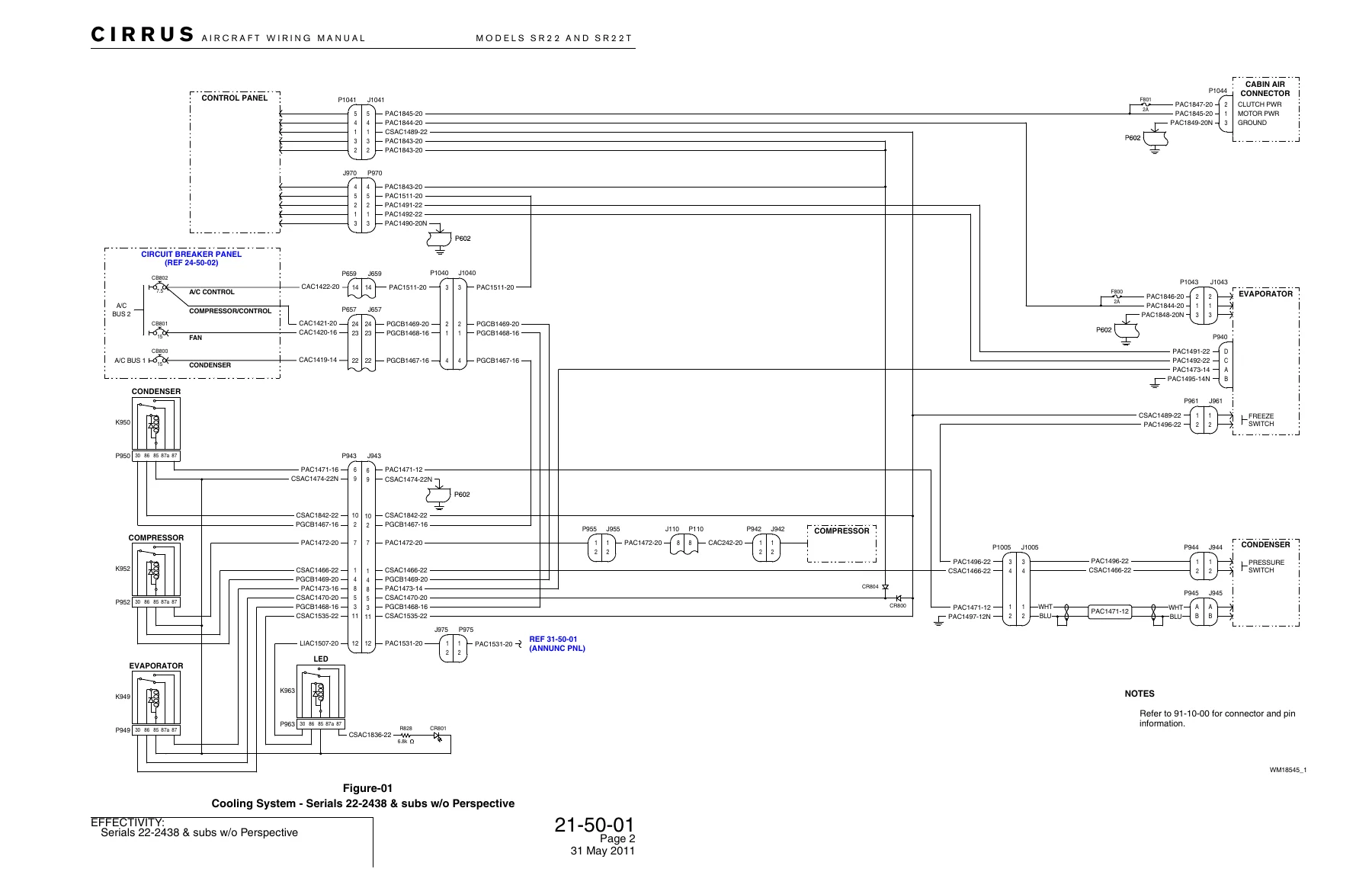
- Chapter 21 — Environmental Systems: Cabin air fan assembly schematics across three production eras (early serials, non-Perspective serials 22-2438 and subs, and Perspective-equipped SR22/SR22T models), cabin air vent assembly, avionics cooling fan circuits, transponder cooling fan, MFD cooling fan, PFD cooling fan, and Keith air conditioning cooling systems (compressor controls, condenser blowers, evaporator fans, freeze switches, and pressure switches).
- Chapter 22 — Auto Flight: S-Tec System 30 autopilot and turn coordinator circuits, S-Tec System 55X autopilot installations (spanning serial blocks from 22-0002 through Perspective crossover airframes), flight director annunciator and relay integration, Perspective Garmin GFC 700 Automated Flight Control System (AFCS) mode control and servo wiring, and Take-Off/Go-Around (TO/GA) switch logic.
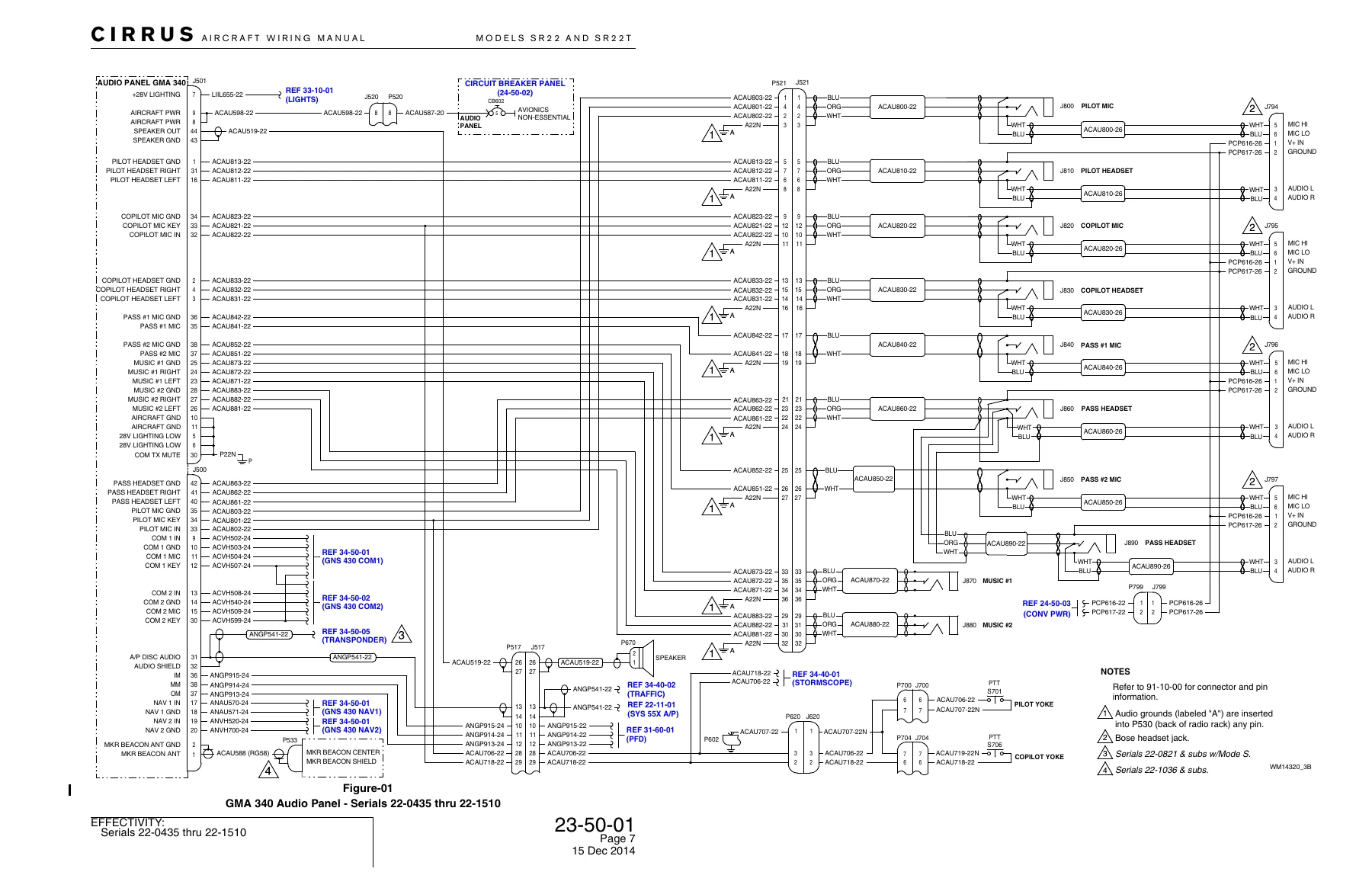
- Chapter 23 — Communications: Garmin GDL 88 ADS-B Universal Access Transceiver (UAT) integration with GIA 63W and PFD units, Garmin GMA 340 audio panel schematics (unswitched audio, marker beacon antenna, microphone keys, music inputs, and Bose headset power jacks), Garmin GMA 347 audio panel with Perspective avionics, and high-density Garmin GMA 350 audio processor installations with 3D audio routing, fail-safe warning inputs, and telephone audio interfaces.
- Chapter 24 — Electrical Power: Master Control Unit (MCU) internal bus schematics and external generation, Alternator 1 and Alternator 2 voltage regulation, Battery 1 and sealed Battery 2 tie circuits, bolster master switch panels, avionics power relays (essential, non-essential, and sheddable buses), extensive circuit breaker panel diagrams across 10 distinct serial evolutions, 12V and 28V convenience power circuits, fluid quantity power supplies, cockpit and passenger USB charger ports, and the solid-state Convenience System Controller with convenience lighting logic.
- Chapter 25 — Equipment and Furnishings: AmSafe crew seat inflatable restraint harness and electronic airbag squib module circuits, RCPI remote ELT switches, Artex ME406 406 MHz emergency locator transmitter installations, and Artex ELT 1000 systems integrated with the CAPS handle activation switch.
- Chapter 27 — Flight Controls: Roll trim actuator and cockpit switch circuitry, roll trim autopilot disconnect relays, yaw trim actuator systems, rudder trim indicators, Garmin Perspective yaw servo wiring, pitch trim motor assemblies with limit switch interlocks, pitch trim relays, pitch trim adapter units, stall warning horn and lift transducer circuits, and multi-position flap control systems (flap switch panel, flap actuator motor, proximity switches, dynamic braking, and flap position relays).
- Chapter 28 — Fuel: Electric fuel boost pump wiring (Prime, Boost, High, and Low modes), starter fuel pump interlocks, gascolator sensor circuits, multi-point resistive float fuel level transmitters, and modern digital frequency-based fuel indicating systems with inboard/outboard senders.
- Chapter 30 — Ice Protection: TKS Basic ice protection metering pumps and cockpit switches, Basic2 de-ice systems, and Flight Into Known Icing (FIKI) dual-metering pump control, windshield de-ice proportioning pumps, high/low pressure sensing switches, TKS fluid quantity tank transmitters, and heated stall warning lift transducer vanes.
- Chapter 31 — Indicating and Recording Systems: CO Guardian carbon monoxide detector circuits, mechanical Hobbs hour meters and dual pressure-switch hour meters, Aircraft Data Logger (ADL) with crash-hardened Recoverable Data Module (RDM), Garmin GIA 63W integrated avionics processors, central annunciator panels, Avidyne and Garmin PFD displays, multi-generation MFD systems (Arnav, Avidyne EX5000C, Garmin Perspective), and PFD/MFD reversionary display switching.
IMAGES PREVIEW
Together, these technical chapters provide avionics technicians, certified repair stations, and aircraft maintenance engineers with complete wire-by-wire visibility across the entire Cirrus airframe. From tracing intermittent bus fault isolation in the Master Control Unit to pinning out new digital avionics interfaces or overhauling flight control servos, this publication delivers the precise engineering data needed to maintain original factory electrical integrity and verify airworthiness compliance.
The Technician’s Essential Electrical Companion
Working on modern, composite general aviation aircraft requires uncompromised precision—especially when troubleshooting high-density digital data buses, dual-bus electrical power generation, or flight-critical autopilot systems. The Cirrus SR22 and SR22T Aircraft Wiring Manual (Revision D6) eliminates guesswork by providing exact factory wire gauge designations, wire part codes, pin-by-pin connector mappings, and relay configurations tailored directly to your specific airframe serial number. Delivered as an instant, high-resolution PDF download, this digital manual provides rapid access on the hangar floor, flight line, or avionics workbench. Viewable on laptops, tablets, and smartphones, it allows you to zoom in on intricate multi-layer schematics, print out full-scale wiring diagrams for active wire chasing, and ensure that every splice, crimp, and terminal replacement adheres rigorously to Cirrus factory aircraft standards.
Reviews
There are no reviews yet.