
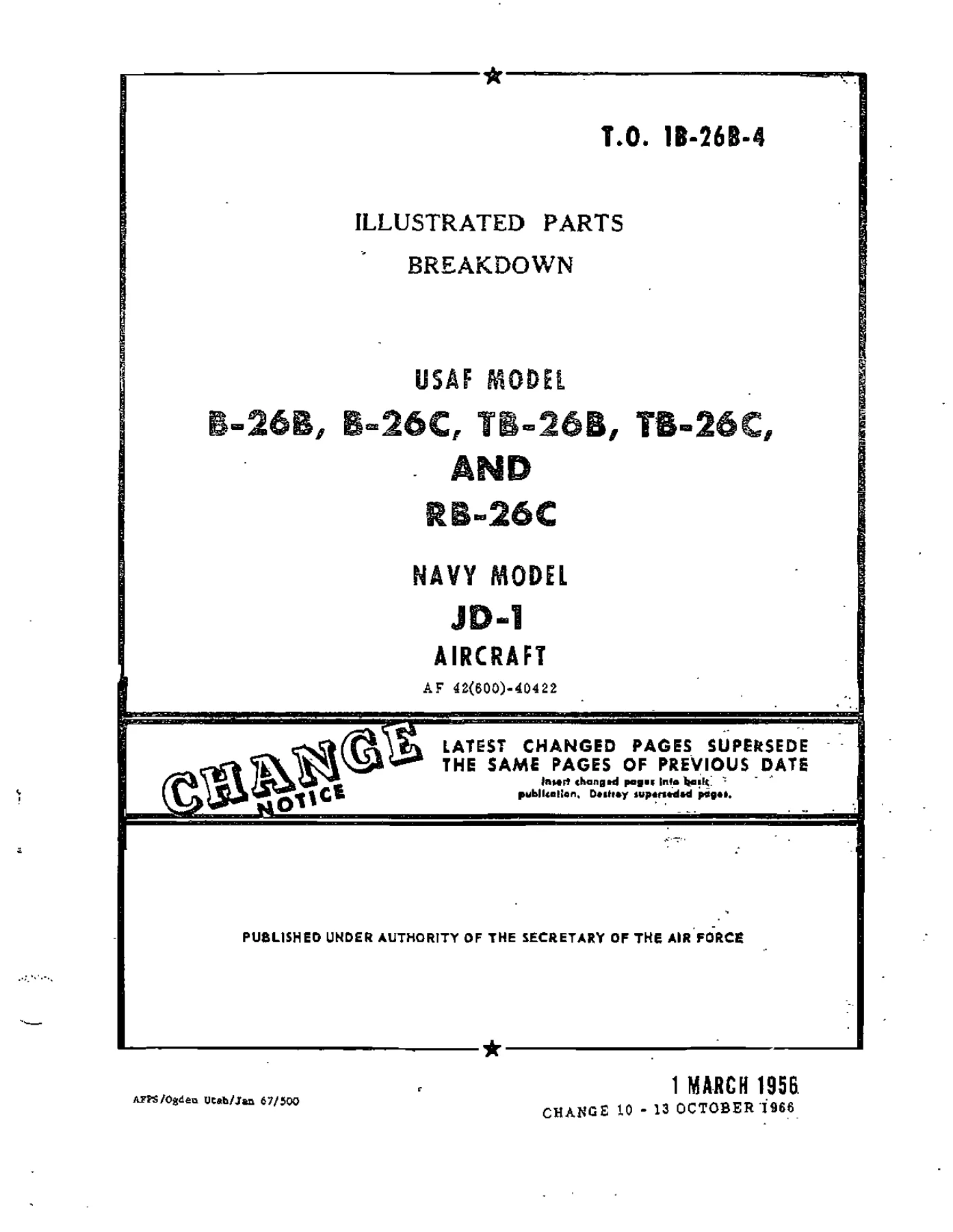
Douglas B-26B, B-26C, TB-26B, TB-26C, RB-26C & Navy JD-1 Aircraft Illustrated Parts Breakdown Manual (T.O. 1B-26B-4)
Original price was: $34.95.$21.95Current price is: $21.95.
Official USAF Technical Order illustrated parts breakdown (T.O. 1B-26B-4) for Douglas B-26B, B-26C, TB-26B, TB-26C, RB-26C, and U.S. Navy JD-1 aircraft. Includes exploded part diagrams, complete assembly breakdowns, attaching hardware callouts, vendor codes, and numerical part indexes.
Description
The Douglas B-26B, B-26C, TB-26B, TB-26C, RB-26C & Navy JD-1 Aircraft Illustrated Parts Breakdown Manual (T.O. 1B-26B-4) is the definitive master parts catalog published under the authority of the Secretary of the Air Force and prepared by Hayes Aircraft Corporation. Engineered for depot-level mechanics, warbird restoration specialists, military aviation historians, and technicians, this technical publication provides complete exploded-view diagrams and itemized parts listings for every structural, mechanical, hydraulic, electrical, and armament assembly across the twin-engine Douglas Invader series. Whether maintaining an airworthy airframe or authenticating historic components, this comprehensive illustrated parts breakdown provides exact part numbers, assembly sequences, and installation relationships down to every bolt, washer, bushing, and bracket.
File Details
- Manual Type: Illustrated Parts Breakdown (USAF Technical Order)
- Technical Order Number: T.O. 1B-26B-4 (AF 42(600)-40422)
- Aircraft Manufacturer: Douglas Aircraft Corp. (Prepared by Hayes Aircraft Corp.)
- Models Covered: USAF B-26B, B-26C, TB-26B, TB-26C, RB-26C; U.S. Navy JD-1
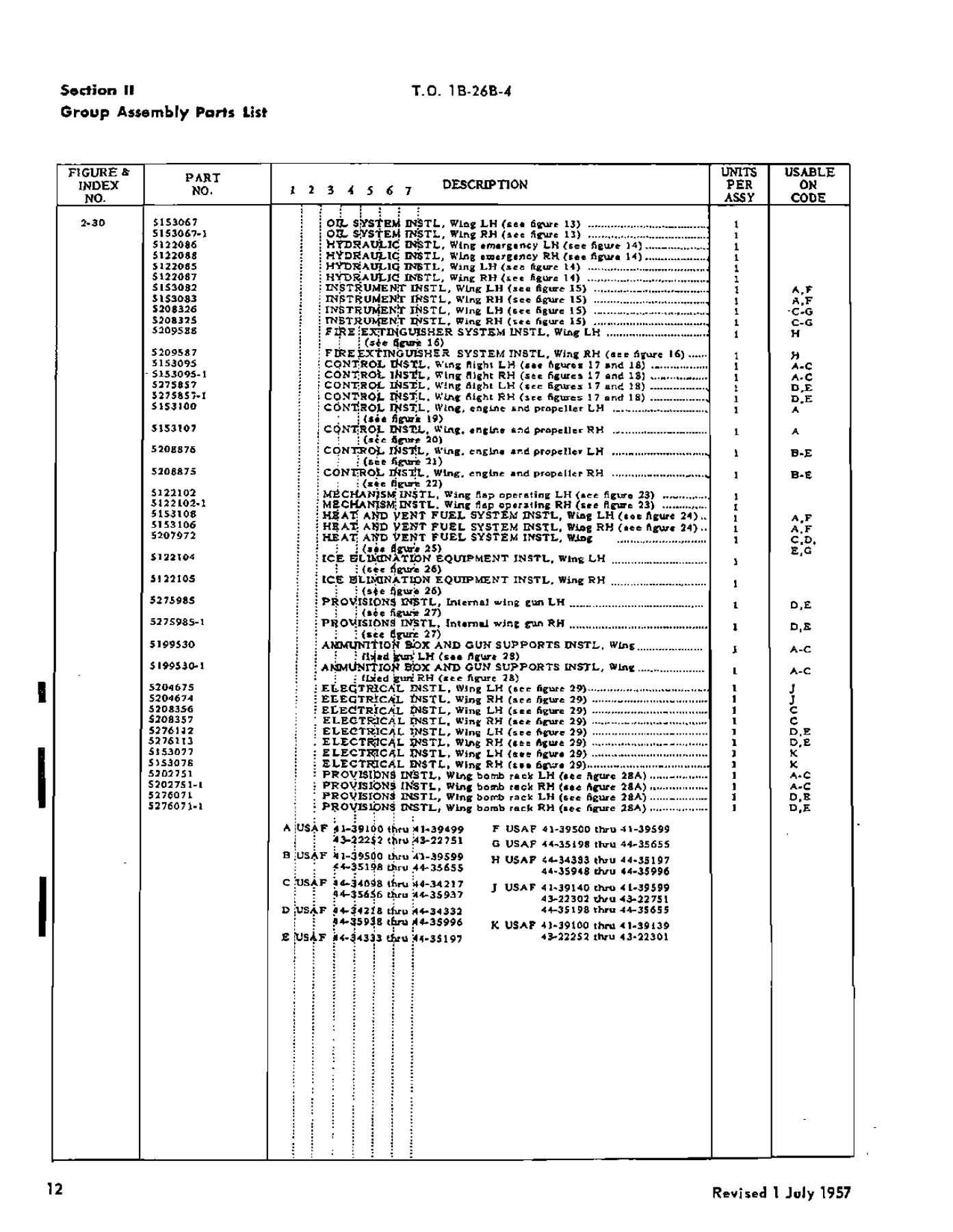
- Serial Number Coverage: USAF 41-39100 thru 41-39599, 43-22252 thru 43-22751, 44-34098 thru 44-35996
- Publication Date: 1 March 1956 (Revised with Change 10 through 13 October 1966)
- Language: English
- Document Page Count: 734 pages
- File Format: PDF
Comprehensive Group Assembly Breakdown
Every major assembly of the aircraft is systematically cataloged across seven functional sections within the Douglas B-26B, B-26C, TB-26B, TB-26C, RB-26C & Navy JD-1 Aircraft Illustrated Parts Breakdown Manual (T.O. 1B-26B-4). Detailed line drawings and exploded views illustrate how detail parts form subassemblies and installations, utilizing an indention system that establishes exact parent-child mechanical relationships:
- Wing Group Architecture: Covers left-hand and right-hand wing installations, wing-to-fuselage fairings, fillet structures, inboard and outboard trailing edges, nacelle structures, engine mount supports, oil cooler air ducts, and structural skin panels. Detailed station-by-station breakdowns cover wing stations from Sta 32 and Sta 34 out to outboard rib assemblies, access covers, and wing tip recognition light assemblies.
- Flight Control Linkages & Actuation: In-depth coverage of aileron installations, trim tab mechanisms, differential bellcranks, control cable pulleys, push-pull rods, and flap actuating mechanisms. Includes complete engineering illustrations of outboard and inboard wing flaps, flap tracks, rotating rods, torque tubes, hinges, limit stops, and mechanical disconnect assemblies.
- Hydraulic & Emergency Systems: Comprehensive schematics and parts listings for wing pressure lines, return circuits, suction manifolds, firewall shutoff valves, landing gear actuating cylinders, brake lines, flexible hose assemblies, emergency hydraulic hand-pump circuits, and dual-piston emergency brake shuttle valves.
- Fuel & Oil Distribution: Complete parts breakdowns of main nacelle fuel cells, wing auxiliary fuel containers, filler necks, booster pumps, selector valves, check valves, and vent lines. Oil system coverage includes nacelle oil tanks, hopper assemblies, oil dilution lines, elliptical oil coolers, thermostatic valves, and electric oil cooler exit flap actuators.
- Power Plant & Nacelle Mechanics: Itemizes firewall mountings, demountable power plant bulkheads, carburetor air induction ducting, nonram antidrag ring supports, cowl flap operating linkages, propeller pitch control assemblies, engine control cable drums, and throttle/mixture bellcrank quadrants.
- Specialized Armament, Ordnance & Equipment: Exploded views of 8-gun nose installations, bombardier transparent nose enclosures, 37mm cannon mount kits, fixed wing machine guns, ammunition boxes, feed chutes, link ejection doors, zero-rail rocket launchers, bomb bay tanks, ferry fuel tanks, and wing bomb rack installations.
- Electrical & Instrumentation: Catalogs firewall junction boxes, master relay assemblies, starter relays, circuit breaker panels, DC/AC inverters, generator bus bars, landing gear position switches, cockpit instrument plumbing, manifold pressure lines, and fluxgate compass systems.
- Crew Station, Escape & Fuselage Structure: Details pilot seating, gunner escape hatches, jettisonable doors, canopy enclosures, sliding windshield panels, camera door installations, and cockpit heating and ventilating ducts.
Chapters Covered
- Section I – Introduction
- Usage Guide & Indention Method
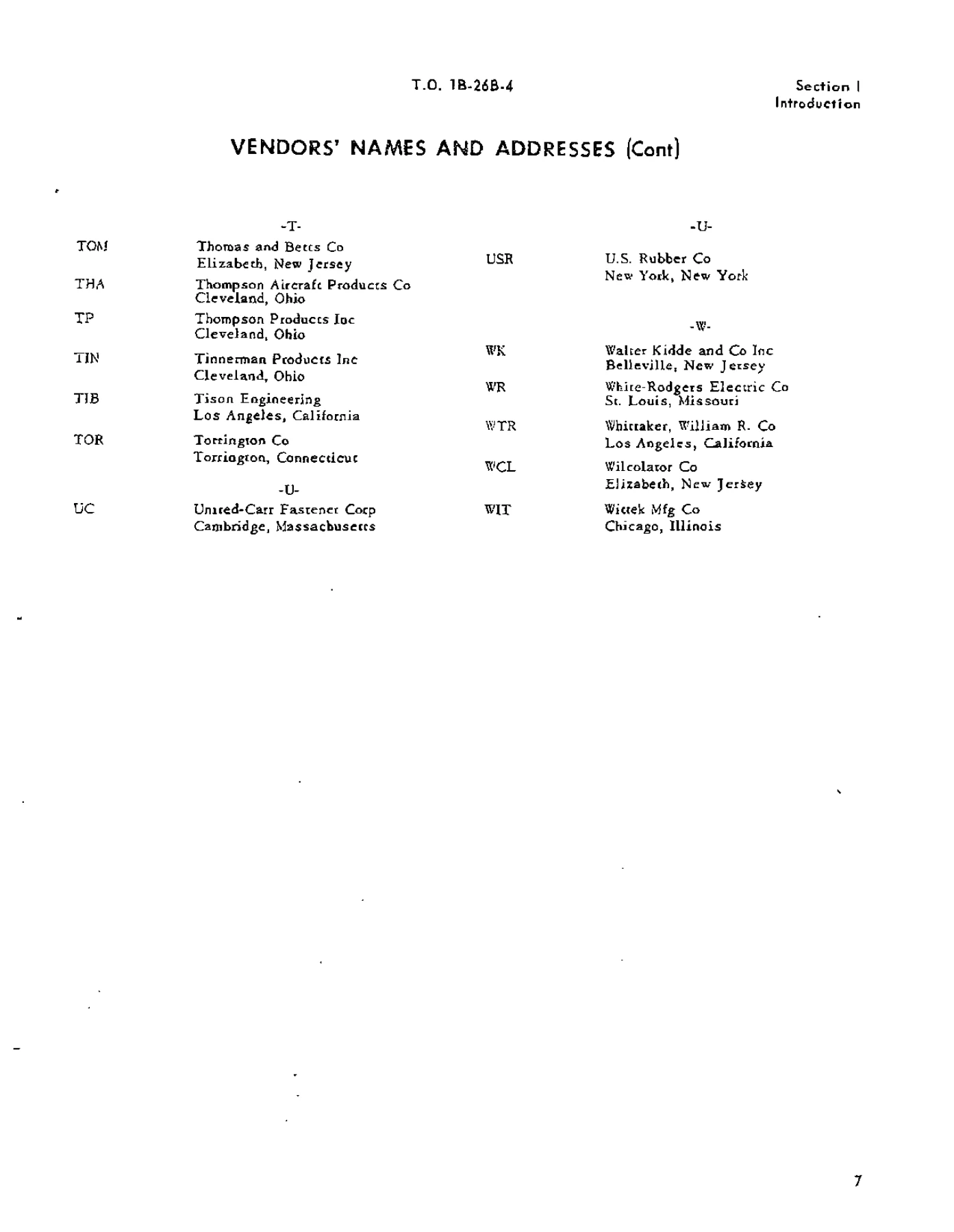
- Vendors’ Names and Addresses Directory
- Figure 1 – Major Assembly Breakdown
- Section II – Group Assembly Parts List
- Wing Group: Complete Wing Structure & Installations
- Wing to Fuselage Fillet and Inboard Trailing Edge Structure
- Aileron and Wing Structure Panel Assemblies
- Nacelle Structure, Firewalls, and Access Doors
- Wing LH and RH Flap Installation (Outboard & Inboard)
- Wing Fuel System, Selector Valves & Boost Pumps
- Nacelle and Wing Fuel Container Installations
- Wing Oil System, Tanks, Coolers & Actuators
- Wing Hydraulic Piping & Emergency Brake Lines
- Power Plant Controls, Quad Drums & Linkages
- Wing Flap Operating Mechanisms & Torque Tubes
- Wing Heat, Vent & Ice Elimination Systems
- Internal Wing Gun Provisions & Ammunition Boxes
- Wing Fixed Gun Pneumatic Charging Equipment
- Wing Bomb Rack Provisions & Release Controls
- Droppable Fuel Tank Displacement Strut Sockets
- Wing Electrical Harnesses, Junction Boxes & Relays
- Trailing Edge & Outboard Wing Panel Assemblies
- Empennage Group: Fin, Rudder, Stabilizer & Trim Tabs
- Fuselage Group: Main Frames, Bulkheads & Cockpit Enclosures
- Bombardier Nose & All-Purpose Gun Nose Assemblies
- Flight Controls, Pedestals, Control Columns & Pulleys
- Fuselage Fixed Fuel, Bomb Bay Tanks & Ferry Tanks
- Fuselage Hydraulic Equipment & Actuating Cylinders
- Fuselage Heating, Ventilating & Soundproofing Kits
- Cockpit Electrical Distribution, Switchboards & Inverters
- Complete Oxygen System Regulators, Valves & Cylinders
- Alighting Gear Group: Main & Nose Gear Struts, Doors & Cylinders
- Power Plant Group: Mounts, Cowl Flaps & Induction Air Ducts
- Electronics Group: Radio, Radar & Navigation Sets
- Armament Group: Turrets, Bomb Racks, Gun Mounts & Armor Plate
- Specialized Service Tools
- Section III – Numerical Index
- Alphabetical Unnumbered Parts Listing
- Alphanumeric Part Number Master Cross-Reference
- Standard Hardware, Stock Code & Figure/Index Callouts
As a technical reference, this manual supplies aviation maintenance technicians, parts procurement specialists, and vintage aircraft restorers with an authoritative record of genuine component configurations. By cross-referencing figure numbers, index callouts, Douglas part numbers, and standard AN/MS hardware specifications, personnel can trace any airframe component back to its exact installation location, verify interchangeable assemblies across specific aircraft serial number blocks, and confirm proper hardware stacking sequences.
Attaching Parts Callouts & Commercial Vendor Codes
A vital feature of this Douglas B-26B, B-26C, TB-26B, TB-26C, RB-26C & Navy JD-1 Aircraft Illustrated Parts Breakdown Manual is its meticulous treatment of attaching parts and military standard hardware. Every installation explicitly lists the required bolts, flat washers, star lockwashers, castle nuts, self-locking stop nuts, and cotter pins needed to secure components to the airframe. The manual clearly distinguishes between field-replaceable parts, depot-manufactured items, and non-procurable structural weldments through standard Air Force source codes (P, P1, M, M1, A, A1, X, X1, X2). Furthermore, Section I cross-references proprietary vendor abbreviation codes back to original American aviation component suppliers—including Aero Supply, Adel, Bendix, Chandler-Evans, Cleveland Pneumatic, Fafnir, Grimes, Jack & Heintz, Pesco, Purolator, and Thompson Products—enabling precise identification and modern sourcing of vintage accessories.
Essential Workshop Capability & Instant Digital Delivery
Whether conducting a 100-hour structural inspection, overhauling landing gear retraction linkages, restoring a combat-veteran Douglas B-26 Invader, or fabricating replacement skin panels to original specifications, having access to an authentic parts catalog prevents costly assembly errors and structural misalignments. The clear isometric mechanical drawings eliminate guesswork when reassembling complex mechanisms such as flap carriages, bomb bay door actuating linkages, and firewall fuel control drums. This publication is delivered as a high-resolution, instant-download PDF file directly following payment, eliminating shipping wait times and international courier costs. Fully accessible across desktop workstations, laptops, workshop tablets, and smartphones, the digital file can be easily navigated using PDF reader search tools or printed out for durable, hands-on bench use in the hangar.


Reviews
There are no reviews yet.