
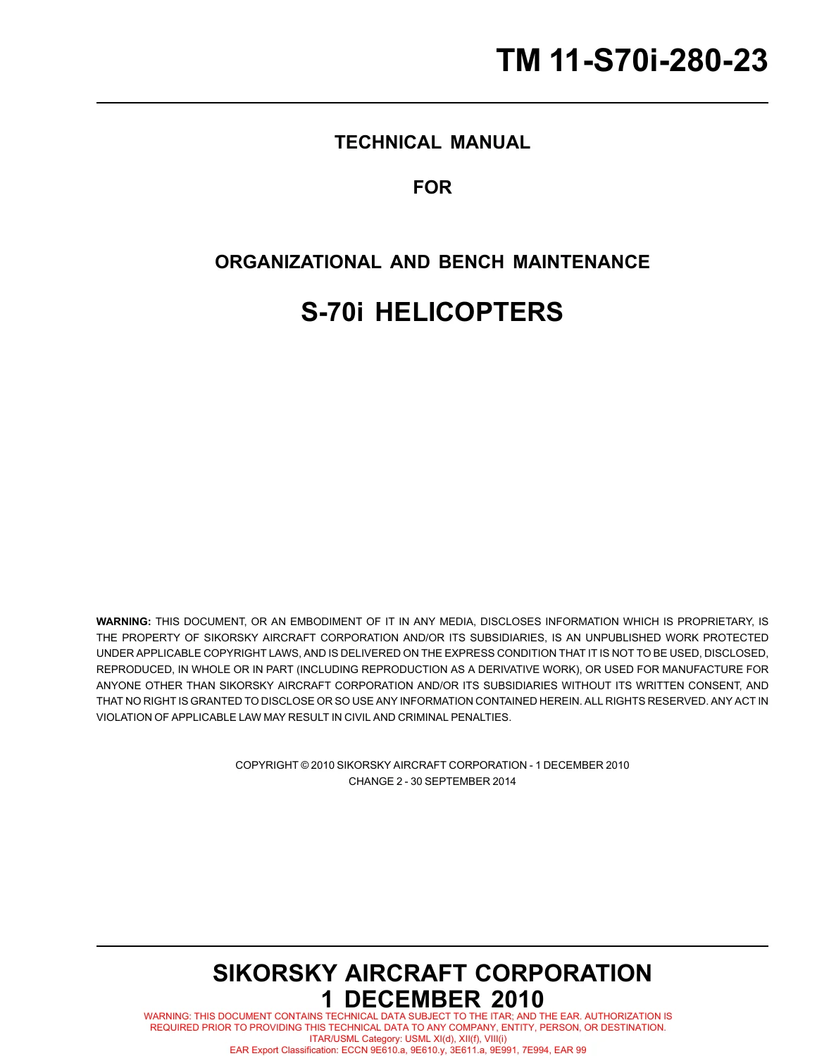
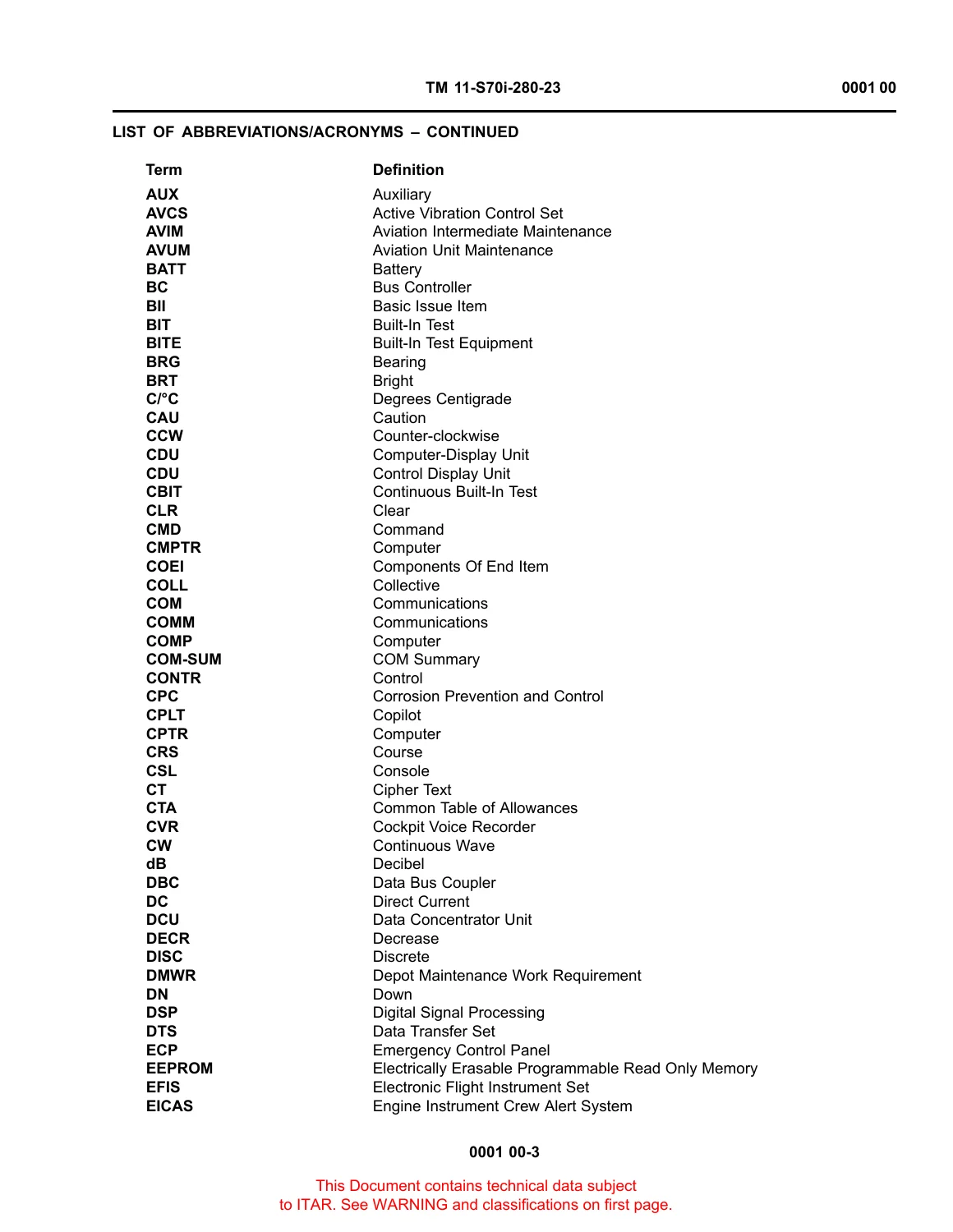

Sikorsky S-70i Helicopter Organizational and Bench Maintenance Manual – TM 11-S70i-280-23 Change 2
Original price was: $39.95.$24.95Current price is: $24.95.
Comprehensive organizational and bench-level avionics maintenance manual for the Sikorsky S-70i helicopter. Features detailed theory of operation, testing, troubleshooting workflows, pinouts, and removal/installation procedures across all primary communication and navigation systems.
Description
Overview of the Sikorsky S-70i Helicopter Organizational and Bench Maintenance Manual – TM 11-S70i-280-23 Change 2
The Sikorsky S-70i Helicopter Organizational and Bench Maintenance Manual – TM 11-S70i-280-23 Change 2 serves as the definitive technical reference for flight line technicians, avionics specialists, and bench repair personnel maintaining the mission and communication electronics of the Sikorsky S-70i utility tactical transport helicopter. Published under technical manual number TM 11-S70i-280-23 and updated through Change 2 dated 30 September 2014, this document delivers comprehensive fault isolation logic, component removal and installation procedures, wiring schematic diagrams, and operational checkout standards across all integrated avionics, radio navigation, and communication suites.
File Details
- Manual Type: Technical Manual for Organizational and Bench Maintenance
- Brand: Sikorsky Aircraft Corporation
- Model: S-70i Helicopters
- Document Number: TM 11-S70i-280-23
- Publication Date: 1 December 2010
- Revision / Change Status: Change 2, dated 30 September 2014
- Language: English
- Page Count: 598
- File Format: Portable Document Format (PDF)
Chapters Covered
- Chapter 1 — General Information, Equipment Description and Theory of Operation
- WP 0001 00 — General Information
- WP 0002 00 — Equipment Description and Data
- WP 0003 00 — Avionics Maintenance Testing Overview Description and Data
- WP 0004 00 — Continuous Built-In Test (CBIT) Equipment Description and Data
- WP 0005 00 — Initiated Built-In Test (IBIT) Equipment Description and Data
- WP 0006 00 — Civil Navigation Equipment Description and Data
- WP 0007 00 — LF/ADF Equipment Description and Data
- WP 0008 00 — Radar Altimeter Equipment Description and Data
- WP 0009 00 — Stormscope Equipment Description and Data
- WP 0010 00 — LOS Multiband (COMM 2) Radio Set (MXF-4027) Description and Data
- WP 0011 00 — LOS Multiband (COMM 3) Radio Set (MXF-4027) Description and Data
- WP 0012 00 — Transponder Set (AN/APX-117(V)) Description and Data
- WP 0013 00 — Emergency Locator Transmitter Set (C406-N HM) Description and Data
- WP 0014 00 — TACAN Set (AN/ARN-153) Description and Data
- Chapter 2 — Organizational and Bench Maintenance Troubleshooting Procedures
- WP 0015 00 — Civil Navigation Troubleshooting
- WP 0016 00 — LF/ADF Troubleshooting
- WP 0017 00 — Emergency Locator Transmitter Troubleshooting
- WP 0018 00 — Radar Altimeter Troubleshooting
- WP 0019 00 — Stormscope Troubleshooting
- WP 0020 00 — LOS Multiband (COMM 2) Radio Set (MXF-4027) Troubleshooting
- WP 0021 00 — LOS Multiband (COMM 3) Radio Set (MXF-4027) Troubleshooting
- WP 0022 00 — Transponder Troubleshooting
- WP 0023 00 — TACAN Troubleshooting
- Chapter 3 — Organizational and Bench Maintenance Instructions
- WP 0024 00 to WP 0028 00 — Civil Navigation Receiver, Mount, Glide Slope Antenna, Marker Beacon Antenna, and VOR/LOC Antenna
- WP 0029 00 to WP 0031 00 — LF/ADF Receiver, Mount, and Antenna
- WP 0032 00 to WP 0033 00 — Radar Altimeter Receiver/Transmitter and Antenna
- WP 0034 00 to WP 0036 00 — Stormscope Processor, Tray, and Antenna
- WP 0037 00 to WP 0043 00 — LOS Multiband (COMM 2) Radio Set Receiver/Transmitter, Mount, Fuses F1/F2, Tunable Antenna, Antenna Logic Unit, Low Pass Filter, and KY-58 Harness
- WP 0044 00 to WP 0052 00 — LOS Multiband (COMM 3) Radio Set Components, Mount, Fuses, Tunable Antenna, ALU, LPF, KY-58 Harness, Control/Indicator, and Control Panel
- WP 0053 00 to WP 0056 00 — Transponder Receiver/Transmitter, Mount, Mode S Addressing, and Lower Antenna
- WP 0057 00 to WP 0059 00 — ELT Control Panel, Transmitter, Battery Pack, and Antenna
- WP 0060 00 to WP 0062 00 — TACAN Set Receiver/Transmitter, Mount, and Lower Antenna
- WP 0063 00 — Illustrated Index of Field Manufactured Items
- Chapter 4 — Supporting Information
- WP 0064 00 — References
- WP 0065 00 — Tool Identification List
- WP 0066 00 — Expendable and Durable Items List
For aviation maintenance technicians, this publication bridges theoretical system engineering and direct flight-line diagnostics. Rather than presenting abstract descriptions, each work package delivers exhaustive operational checkout sequences, interface wiring schematics, and pinpoint troubleshooting fault trees. By detailing signal flow across the MIL-STD-1553B data bus, ARINC 429 communication channels, and discrete analog interfaces, the manual equips technicians with the precise technical parameters required to rapidly isolate degraded LRUs, address wiring harness faults, and verify full operational readiness before aircraft dispatch.
Major Avionics Systems & Component Nomenclature
The following table outlines the primary avionics subsystems, military alphanumeric nomenclature, operational bandwidths, and physical LRU locations detailed throughout the technical manual:
| Subsystem / Role | Nomenclature / Model | Operating Band / Parameters | Primary LRU Location |
|---|---|---|---|
| Civil Navigation (VOR/ILS) | R-2594/ARN-147(V) | 108.00–117.95 MHz (VOR/LOC), 329.15–335.00 MHz (GS), 75 MHz (MB) | Nose Compartment |
| Low Frequency / Automatic Direction Finder | R-2382/ARN-149(V)1 | 100.0 to 2199.5 kHz (0.5 kHz spacing) | Nose Shelf (Receiver) / Aft Cabin Underside (Antenna) |
| Radar Altimeter Set (RADALT) | RT-1836 / Solid-State R/T | 0 to 1000 ft AGL terrain clearance (analog dial & digital readout) | Pilot Seatwell (R/T) / Nose Underside (Antennas) |
| Line of Sight Multiband Radio (COMM 2) | MXF-4027 | 30.000 to 512.000 MHz (VHF/UHF, AM/FM, HAVEQUICK ECCM) | Nose Shelf (R/T) / Tailcone Underside (Tunable Antenna) |
| Line of Sight Multiband Radio (COMM 3) | MXF-4027 with C-12601 Panel | 30.000 to 512.000 MHz (VHF/UHF, AM/FM, HAVEQUICK ECCM) | Aft Transition / Tailcone Shelf |
| Transponder Set (IFF) | RT-1836(C)/APX-117(V) | 1030 MHz receive / 1090 MHz transmit (Modes 1, 2, 3A, C, S) | Aft Transition Shelf |
| Emergency Locator Transmitter | C406-N HM | 121.5 MHz, 243.0 MHz, and 406.028 MHz distress emergency beacon | Rear Transition Area (Transmitter) / Lower Console (Panel) |
| Tactical Air Navigation (TACAN) | AN/ARN-153(V) | 252 Channels (1025–1150 MHz XMT, 962–1213 MHz RCV) | Transition Avionics Shelf |
| Weather Mapping (Optional) | Stormscope WX-500 | 360° lightning discharge detection up to 100 NM range | Transition Upper Shelf (Processor) / Cabin Belly (Antenna) |
Avionics Architecture & System Integration
The Sikorsky S-70i Helicopter Organizational and Bench Maintenance Manual – TM 11-S70i-280-23 Change 2 details an advanced digital avionics architecture coordinated by dual Flight Management Sets (FMS) acting as bus controllers and remote terminals across dual redundant MIL-STD-1553B digital data buses (Bus A and Bus B). Built-in testing operates through three integrated tiers: Power-Up Built-In Testing (PBIT), which verifies equipment initialization and hardware integrity in under five minutes; Continuous Built-In Testing (CBIT), running unobtrusively in the background every two seconds without taking line-replaceable units off-line; and Initiated Built-In Testing (IBIT), providing operator-activated, interruptive diagnostic routines to thoroughly interrogate line-replaceable units. Technicians interface with these diagnostic routines directly through the pilot and copilot FMS control display units and four active-matrix liquid crystal Multifunction Displays (MFDs) configurable as Primary Flight Displays (PFDs) and Engine Instrument Crew Alert System (EICAS) screens.
Comprehensive Subsystem Troubleshooting & Operational Testing
Technicians working with this TM 11-S70i-280-23 technical manual will find meticulous, step-by-step procedures for every mission and navigation set on board the S-70i. The coverage encompasses the Civil Navigation Set (AN/ARN-147(V)), covering VOR, localizer (LOC), glideslope (GS), and marker beacon (MB) operations, including RF signal checks with external ramp testers; the Low Frequency / Automatic Direction Finder Set (AN/ARN-149(V)) operating across 100 to 2199.5 kHz; the solid-state Radar Altimeter (RADALT) subsystem delivering instantaneous clearance data from 0 to 1000 feet with automated low and high bug audio and visual alerts; the optional Stormscope weather mapping sensor providing 360-degree lightning strike and storm cell detection within 100 nautical miles; Line of Sight Multiband Radio Sets (MXF-4027 COMM 2 and COMM 3) operating across 30 to 512 MHz with HAVEQUICK ECCM and antenna logic tuning units; the AN/APX-117(V) IFF Transponder operating Modes 1, 2, 3A, C, and S; and the C406-N HM Emergency Locator Transmitter providing tri-frequency distress broadcast capability on 121.5, 243.0, and 406.028 MHz.
Professional Maintenance Capability & Practical Application
This Sikorsky S-70i organizational and bench maintenance manual empowers military, municipal, and commercial S-70i fleet technicians to perform complete avionic troubleshooting, bench-level testing, scheduled preventative checks, and line-replaceable unit changeouts with uncompromising accuracy. By adhering directly to the factory-authorized step-by-step diagnostic trees, multimeter resistance tests, connector pinout tables, and schematic diagrams contained in this publication, maintenance teams can prevent costly component misdiagnoses, verify wiring harness integrity, and maintain full compliance with military airworthiness standards. Available as an instant, downloadable PDF with no waiting for physical media or shipping delays, this electronic manual is fully printable, hyper-portable, and ready for immediate deployment on tablets, laptops, or workshop workstations directly on the flight line or in the maintenance hangar.



Reviews
There are no reviews yet.