
Garmin G1000 NXi King Air 200 Series System Maintenance Manual (STC SA01535WI-D ICA)
Original price was: $44.95.$27.95Current price is: $27.95.
Comprehensive 408-page technical service and maintenance manual with Instructions for Continued Airworthiness (ICA) for the Garmin G1000 NXi Integrated Flight Deck and GFC 700 AFCS installed in Beechcraft King Air 200 Series turboprops under STC SA01535WI-D. Includes full LRU diagnostics, wiring diagrams, configuration procedures, periodic inspection intervals, and return-to-service testing.
Description
Garmin G1000 NXi King Air 200 Series System Maintenance Manual Overview
The Garmin G1000 NXi King Air 200 Series System Maintenance Manual (STC SA01535WI-D ICA) is the definitive technical resource and Instructions for Continued Airworthiness (ICA) document required to maintain, inspect, troubleshoot, and service the Garmin G1000 NXi Integrated Avionics System and GFC 700 Automatic Flight Control System (AFCS). Specifically developed for the Textron Aviation / Beechcraft King Air 200 turboprop series under FAA Supplemental Type Certificate (STC) SA01535WI-D, this manual fulfills all regulatory airworthiness criteria set forth under 14 CFR Part 23.1529 and Appendix G. Whether your aircraft is configured with Pratt & Whitney Canada PT6A-41, PT6A-42, PT6A-52, or PT6A-61 powerplants, this document details exact factory maintenance procedures, line replaceable unit (LRU) removal and replacement steps, automated software configuration loading, fault isolation sequences, and return-to-service checkout routines.
Document & Publication File Details
- Manual Type: System Maintenance Manual (SMM) and Instructions for Continued Airworthiness (ICA)
- Garmin Document Part Number: 190-00915-N1
- Document Revision: Revision 5 (Released April 30, 2019)
- Approved STC Reference: FAA STC SA01535WI-D (Master Drawing List 005-00421-00 Rev. 28, System Software v2286.07)
- General Arrangement Drawing: 005-00421-N3 Rev 1 or subsequent
- Applicable Aircraft Models: Beechcraft / Textron Aviation King Air 200, 200C, B200, B200C, B200GT, and B200CGT
- Supported Powerplants: Pratt & Whitney Canada PT6A-41, PT6A-42, PT6A-52, and PT6A-61 turboprops
- Total Page Count: 408 pages
- Language: English (standard aeronautical units of measure)
- Format: High-resolution searchable PDF download
Integrated Flight Deck & System LRU Architecture
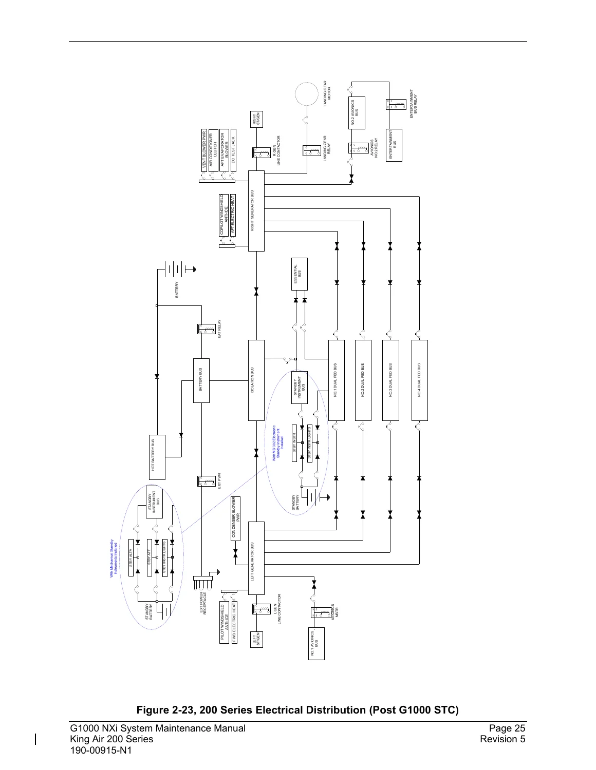
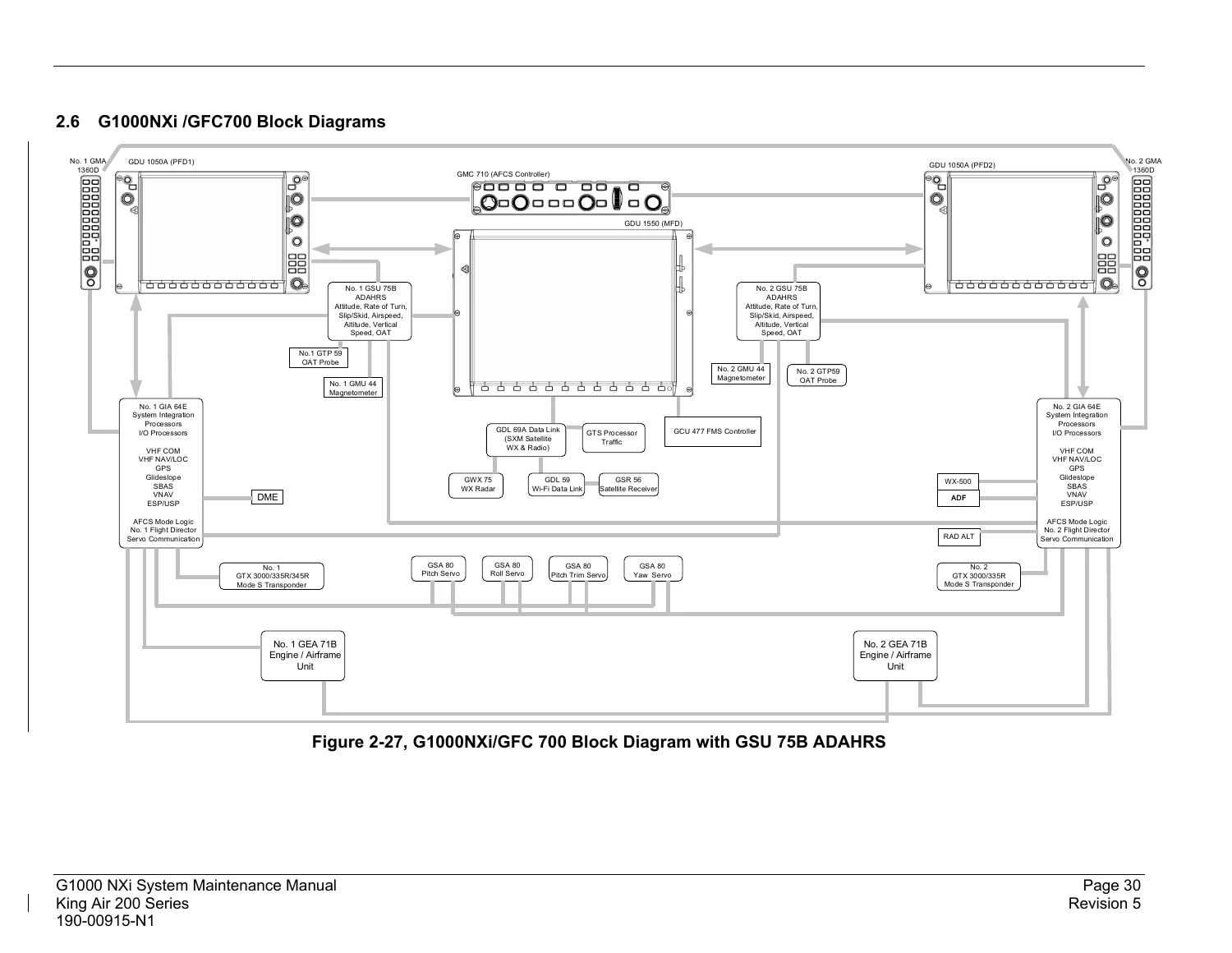
This technical manual provides complete wiring schematics, interconnect diagrams, power bus distributions, and mechanical interface breakdowns for all line replaceable units installed across the airframe under STC SA01535WI-D. Detailed coverage includes:
IMAGES PREVIEW
- Displays: Dual GDU 1050A 10.4-inch high-resolution Primary Flight Displays (configured as PFD 1 and PFD 2) and one central GDU 1550 15-inch Multi-Function Display (MFD) with high-speed Ethernet (HSDB) databus interconnectivity.
- Dedicated Flight Deck Controllers: Pedestal-mounted GCU 477 FMS alphanumeric controller and the glareshield-mounted GMC 710 AFCS digital autopilot control unit.
- Digital Audio Panels: Dual GMA 1347D or GMA 1360D audio systems featuring integrated intercom, digital clearance recorder, marker beacon receivers, and manual display backup (reversionary mode) control.
- Integrated Avionics Units (IAUs): Dual remote GIA 63W (P/N 011-01105-01 / 011-01105-20) or advanced GIA 64E units housing VHF COM/NAV, SBAS/WAAS GPS receivers, primary flight directors, and system central microprocessors, including optional ARINC 717 Flight Data Recorder (FDR) interfaces.
- Engine & Airframe Units (EAUs): Dual GEA 71 or GEA 71B processors interfacing with Meggitt/Vibro-Meter signal conditioners for torque, ITT thermocouples, N1 gas generator, N2 propeller speed, fuel flow, oil temperature, and oil pressure transmitters.
- Attitude, Heading & Air Data: Dual GSU 75B integrated ADAHRS (or dual GDC 74B / GDC 7400 digital air data computers paired with GRS 77 / GRS 7800 AHRS), dual GMU 44 magnetometers, and dual fuselage-mounted GTP 59 outside air temperature (OAT) probes.
- Transponders & Traffic Surveillance: Dual GTX 33/33D Mode S, GTX 3000 (TCAS II compliant), GTX 335R (ADS-B Out), or GTX 345R (ADS-B In/Out with TAS/TCAS coordination), alongside GTS 820/850 or GTS Traffic Processors (GTS 825 TAS, GTS 855 TCAS I, GTS 8000 TCAS II).
- Radar & Datalink Systems: Nose-mounted GWX 68, GWX 70, or GWX 75 solid-state digital airborne weather radar; GDL 69A / GDL 69A SXM SiriusXM weather/audio hub; optional GDL 59 Wi-Fi datalink; GSR 56 Iridium satellite transceiver; and Flight Stream 510 wireless Connext MMC.
- GFC 700 Automatic Flight Control System: Digital fail-passive pitch, roll, yaw damper, and high-speed pitch trim control driven by four GSA 80 electromechanical servos mated to adjustable GSM 85A or fixed-cartridge GSM 86 servo gearboxes, including optional Electronic Stability and Protection (ESP) and Underspeed Protection (USP).
- Standby Systems: Mid-Continent MD 302 Standby Attitude Module (SAM) electronic 3-in-1 standby instrument or analog mechanical cluster (standby attitude, airspeed, altimeter) backed by an L-3 PS-835 emergency battery system.
Instructions for Continued Airworthiness (ICA) & Scheduled Maintenance
The Garmin G1000 NXi King Air 200 Series System Maintenance Manual directly aligns with the standard Beechcraft 200-hour phase inspection program (Phases 1 through 4 spanning an 800-hour or 24-calendar-month complete cycle). Chapter 4 outlines mandatory FAA Airworthiness Limitations (Section 4.1) and comprehensive scheduled maintenance instructions:
- Mandatory Airworthiness Limitation Checks: Pitch trim annunciator operational checks (every 220 hours), GSM 85A slip clutch torque testing (every 420 hours), GSM 86 slip clutch torque checks (every 3,000 hours), Weight on Wheels (WOW) and Low Speed Awareness Band checks (every 220 hours), G1000 redundant connection verification (every 220 hours), power bus feeder check (every 620 hours), engine data check (every 820 hours), G1000 miscompare checks (every 820 hours), antenna exterior skin crack and fastener inspections (initial at 10,000 flight cycles, repetitive every 1,000 cycles), and standby battery periodic checks (every 220 hours or 6 calendar months).
- Zone Visual Inspections: Step-by-step visual inspection checklists covering the nose radar radome section, nose avionics compartment, flight deck and pedestal, main instrument panel, cabin underfloor bays (FS 185.00 and FS 246.750), and the rear fuselage/empennage tailcone.
- Electrical Bonding Tests: Milliohm resistance testing using calibrated Kelvin probes, establishing maximum allowable bonding thresholds of 30 mΩ for instrument panel displays and the GMC 710, and 5 mΩ for remote LRUs, antennas, and lightning protection points.
- RVSM Qualification: Instructions and critical air data inspections necessary to maintain Reduced Vertical Separation Minimum (RVSM) group airworthiness compliance under 14 CFR Part 91 Appendix G, including skin waviness and static port measurements using Beechcraft SPF-4 gauging tools.
Automated Software Loading, LRU Configuration & Feature Unlock Procedures
Section 3 of the Garmin G1000 NXi King Air 200 Series System Maintenance Manual provides exact guidance for field service engineers to perform baseline software loads, configuration updates, and optional feature enablements using authorized Garmin SD loader cards:
- Configuration Mode Navigation: Detailed explanations of the configuration architecture, SET versus ACTIVE column parameters, PFD master configuration module synchronization, and crossfill integrity checks.
- Sequential Software Loading: Pre-requisite GIA 63W Boot Block 6.10 installation, followed by PFD 2, MFD, and PFD 1 GDU software uploads, baseline profile uploads, and model-specific airframe/engine/propeller matrix matching (supporting Hartzell 3-blade, Hartzell 4-blade, Hartzell Raisbeck 4-blade, McCauley 3-blade, and McCauley 4-blade configurations).
- Optional Feature Enablement: Step-by-step instructions for activating Jeppesen ChartView, Dual Charts, SurfaceWatch runway safety monitoring, GWX 70/75 Doppler Turbulence Detection and Ground Clutter Suppression, Class A and Class B TAWS, Synthetic Vision Technology (SVT), Search and Rescue (SAR) search patterns, and Enhanced AFCS (ESP/USP).
- Avionics Calibration & Database Loading: Complete procedures for entering aircraft registration (tail number, 24-bit ICAO hexadecimal address, VFR code, Flight ID), configuring the MD 302 SAM, updating Flight Stream 510 firmware, and loading aviation terrain, obstacle, navigation, and airport directory databases.
Complete Chapters Covered
- Section 1: INTRODUCTION — Content, Scope, Purpose (1.1); Organization (1.2); Definitions/Abbreviations (1.3); Units of Measure (1.4); Publications & Reference Documents (1.5); Revision and Distribution (1.6)
- Section 2: SYSTEM DESCRIPTION — Equipment Descriptions (2.1); G1000 Optional Interfaces (2.2); Electrical Power Distribution (2.3); Pitot/Static System Schematics (2.4); Shield Block Grounds (2.5); G1000NXi/GFC 700 Block Diagrams (2.6); GDU 1050A and GDU 1550 Displays (2.7); Softkeys (2.8); FMS Knob (2.9); GCU 477 MFD Controller (2.10); GMC 710 AFCS Controls (2.11); GMA Audio Panels (2.12); G1000 Normal Mode (2.13); Reversionary Mode (2.14)
- Section 3: SOFTWARE AND CONFIGURATION — Configuration Mode Overview (3.1); G1000 System Software Information (3.2); Configuration Mode Operations (3.3); Hardware/Software Compatibility Check (3.4); Equipment Verification & S/N Identification (3.5); Configuration Checklist (3.6); Software/Configuration Procedure (3.7); System Software and Configuration Load (3.8); Feature Enablement (3.9); Aircraft Registration Number Entry (3.10); Configuration Manager (3.11); Splash Screen Loading (3.12); Clearing Default User Settings (3.13); Database Loading via SD/FS510 (3.14); Traffic Map Configuration (3.15); Enter Flight ID (3.16); GRA 5500 Legacy Configuration (3.17); Interface Confirmation (3.18); MD 302 Configuration & Sensor Calibration (3.19); Flight Stream 510 Firmware Updates (3.20)
- Section 4: INSTRUCTIONS FOR CONTINUED AIRWORTHINESS — Airworthiness Limitations (4.1); Servicing Information (4.2); Maintenance Intervals Table 4-1 (4.3); Visual Inspections (4.4); Electrical Bonding Tests (4.5); Earth Magnetic Field Updates (4.6); GSA 80 Greasing (4.7); Flaps-in-Motion Check (4.8); GSM 85A/86 Slip Clutch Torque Checks (4.9); G1000 Redundant Connection Check (4.10); Engine Data Check (4.11); Trim Annunciator Check (4.12); Miscompare Checks (4.13); Cooling Fan Checks (4.14, 4.15); Standby Battery Checks (4.16); Power Bus Checks (4.17); Antenna Skin Inspections (4.18)
- Section 5: TROUBLESHOOTING — System Annunciations (5.1); Alerting System (5.2); Aural Alerts (5.3); King Air Specific Alerts (5.4); TAWS Fault Isolation (5.5); Synthetic Vision Troubleshooting (5.6); GFC 700 AFCS Faults (5.7); General Troubleshooting (5.8); Backup Paths (5.9); GDU 105X Display Diagnostics (5.10, 5.11); GIA IAU Troubleshooting (5.12, 5.13); GEA Engine Interface Faults (5.14); GTX Transponder Faults (5.15); Datalink & Radar Troubleshooting (5.16, 5.19); ADAHRS, AHRS & GMU 44 Diagnostics (5.17, 5.18); Controller Diagnostics (5.20, 5.21); Connector Pinouts & Standby Instrumentation Diagnostics (5.23–5.32)
- Section 6: EQUIPMENT REMOVAL AND INSTALLATION — Complete mechanical removal, structural mounting, and connector mate/demate procedures for all 35 G1000 NXi LRUs, sensors, racks, cooling fans, and external airframe antennas
- Section 7: GARMIN G1000 LRU REPLACEMENT/CONFIGURATION & TESTING — Post-installation software configuration, diagnostic verification, sensor calibrations (pitch/roll offset, magnetometer calibration, engine instrument test points), and air data system leak/accuracy tests for individual replaced units
- Section 8: SUBSYSTEM FUNCTIONAL CHECKS — Ground testing for Stormscope, TAWS, SVS, charts, radar altimeters, WOW logic, RVSM checks, Safe Flight lift computer calibration, and ESP protection modes
- Section 9: G1000 SYSTEM RETURN TO SERVICE PROCEDURE — Final flight-readiness validation including display power-up, reversion tests, cooling fail circuits, GPS acquisition, GIA failure tests, GEA checks, standby power verification, GFC 700 full ground checkout, and maintenance record entry requirements
Together, these nine comprehensive sections equip licensed avionics technicians, King Air fleet operators, and Part 145 repair stations with an authoritative, factory-engineered roadmap to keep G1000 NXi-equipped King Air 200 series aircraft flying safely, reliably, and fully compliant with all FAA airworthiness mandates.
Professional Capability, Regulatory Compliance & Instant Digital Access
Owning the complete Garmin G1000 NXi King Air 200 Series System Maintenance Manual (STC SA01535WI-D ICA) directly empowers aviation maintenance technicians and flight departments to perform sophisticated avionics troubleshooting in-house, eliminating excessive aircraft downtime and costly trial-and-error parts swapping. From resolving complex ARINC 429 digital bus faults and GFC 700 autopilot servo clutch adjustments to executing precision RVSM recalibrations and routine 200-hour phase inspections, this manual provides the exact tolerances, torque specifications, pinout schematics, and test limits needed to maintain certified airworthiness standards. Available as an instant PDF download immediately upon checkout, this digital manual contains no DRM restrictions—allowing you to store it locally on your flight bag iPad, maintenance laptop, or shop workstation, or print high-resolution physical pages for immediate use on the hangar floor.

Reviews
There are no reviews yet.