
Beechcraft King Air and Airliner Series Printed Circuit Board Manual P/N 98-39117F
Original price was: $39.95.$24.95Current price is: $24.95.
Comprehensive workshop reference for testing, troubleshooting, and repairing avionics and electrical circuit boards across Beechcraft King Air 90, 200, 300, 350 and Airliner 99, 1900 series aircraft. Features full ATA 20 and 39 maintenance practices, schematic layouts, component reference designators, and detailed airframe zone diagrams in an instant-access digital PDF.
Description
Beechcraft King Air and Airliner Series Printed Circuit Board Manual P/N 98-39117F
The Beechcraft King Air and Airliner Series Printed Circuit Board Manual P/N 98-39117F is the definitive technical reference dedicated to the testing, troubleshooting, component identification, and repair of printed circuit board assemblies across Beech Aircraft Corporation and Raytheon Aircraft Company twin-turboprop fleets[cite: 1]. Developed under General Aviation Manufacturers Association (GAMA) Specification No. 2 and structured around standard Air Transport Association (ATA) system designations, this manual provides electrical technicians, avionics specialists, and fleet maintenance facilities with factory-level circuit analysis, board layout tracings, and component-level indexing[cite: 1].
File Details
- Manual Type: Printed Circuit Board Manual[cite: 1]
- Brand: Raytheon Aircraft Company / Beech Aircraft Corporation[cite: 1]
- Model Coverage: Beechcraft King Air Series and Airliner Series[cite: 1]
- Publication Part Number: 98-39117F (Reissue F)[cite: 1]
- Publication Issue Date: October 9, 1998 (with ATP Revision Index)[cite: 1]
- Language: English[cite: 1]
- Page Count: 901 pages[cite: 1]
- File Format: Adobe PDF[cite: 1]
Chapters & Systems Covered
- General Information: Manufacturer Title Page, Record of Revisions, Reissue Highlights, and Introduction[cite: 1]
- Section 20.00.00 — Standard Practices (Airframe): General airframe wiring standards, circuit symbology, and wiring conventions[cite: 1]
- Section 20.00.01 — Electrostatic Discharge Sensitivity: ESD-sensitive maintenance practices, component handling precautions, and workstation grounding protocols[cite: 1]
- Section 20.10.00 — Printed Circuit Board Repair Procedures: Inspection criteria, solder repair, component replacement standards, and guidelines confirming that minor circuit board discoloration does not constitute grounds for replacement[cite: 1]
- Section 39.00.00 — Electrical Panels and Multipurpose Parts: Master numerical listing, panel distributions, and multipurpose circuit assemblies[cite: 1]
- Section 39.60.00 — Printed Circuit Board Assemblies: Master equipment lists, board layouts, test procedures, and schematic wiring diagrams[cite: 1]
- Sections 39.61.00 to 39.61.05: Ice Vane Sense, N1 Speed, and Battery Charge Monitor PCB Assemblies and Schematics[cite: 1]
- Sections 39.61.10 to 39.61.13: Annunciator Control PCB Assemblies and Schematics[cite: 1]
- Sections 39.61.20 to 39.61.23: Annunciator Fault Detection PCB Assemblies and Schematics[cite: 1]
- Sections 39.61.30 to 39.61.36: Advisory Light Test, Surface Deice, and Time Delay PCB Assemblies and Schematics[cite: 1]
- Sections 39.61.40 to 39.61.46: Battery Monitor, Ambient Air, Brake Deice, Bleed Air Time Delay, and Propeller Ground Solenoid Annunciator Time Delay Assemblies[cite: 1]
- Sections 39.61.50 to 39.61.51: Bus Tie Control PCB Assemblies and Schematics[cite: 1]
- Sections 39.61.60 to 39.61.62: External Power Overvoltage Sensor and Advisory Light PCB Assemblies[cite: 1]
- Sections 39.61.70 to 39.61.72: Logic Relay PCB Assemblies and Schematics[cite: 1]
- Sections 39.61.80 to 39.61.81: Fire Extinguisher Monitor PCB Assemblies and Schematics[cite: 1]
- Sections 39.61.90 to 39.61.93: Time Delay Relay PCB Assemblies and Schematics[cite: 1]
- Sections 39.62.10 to 39.62.11: Annunciator Legend Power Source PCB Assemblies[cite: 1]
- Sections 39.62.20 to 39.62.31: Bleed Air Control PCB Assemblies and Schematics[cite: 1]
- Sections 39.62.40 to 39.62.41: Auxiliary Fuel Pump Control PCB Assemblies[cite: 1]
- Sections 39.62.50 to 39.62.51: Hydraulic Landing Gear Time Delay PCB Assemblies[cite: 1]
- Sections 39.62.60 to 39.62.82: Fuel Transfer PCB Assemblies and System Schematics[cite: 1]
- Sections 39.62.70 to 39.62.71: Air Conditioner Kit PCB Assemblies and Controls[cite: 1]
- Sections 39.62.90 to 39.62.92: Brake Deice, Left Ice Vane Sense, and External Power Overvoltage PCB Assemblies[cite: 1]
- Sections 39.63.10 to 39.63.11: Bus Tie Control PCB Assembly Maintenance Practices[cite: 1]
- Sections 39.63.20 to 39.63.31: Annunciator Fault Detection and Left Annunciator Fault Detector PCB Assemblies[cite: 1]
- Sections 39.63.40 to 39.63.41: Annunciator Control PCB Assemblies[cite: 1]
- Sections 39.63.50 to 39.63.51: Electronic Time Delay PCB Assemblies[cite: 1]
- Sections 39.63.60 to 39.63.61: External Power Advisory Light PCB Assemblies[cite: 1]
- Sections 39.63.70 to 39.63.71: Time Delay and Annunciator Test PCB Assemblies[cite: 1]
- Sections 39.63.80 to 39.63.83: N1 Speed, Low Pitch, and Ice Vane Sense PCB Assemblies[cite: 1]
- Sections 39.63.90 to 39.63.91: Fire Extinguisher Monitor PCB Assemblies[cite: 1]
- Sections 39.64.10 to 39.64.11: Emergency Exit Lights PCB Assemblies[cite: 1]
- Sections 39.64.20 to 39.64.21: Annunciator Legend Power Source PCB Assemblies[cite: 1]
- Sections 39.64.30 to 39.64.31: Autofeather PCB Assemblies and Circuit Board Layout Revisions[cite: 1]
- Sections 39.64.40 to 39.64.41: Fuel Transfer and Anti-Skid Brakes PCB Assemblies[cite: 1]
- Sections 39.64.50 to 39.64.52: Power Steering Relay Panel PCB Assemblies[cite: 1]
- Sections 39.64.60 to 39.64.62: Surface Deice PCB Assemblies and Schematics[cite: 1]
- Sections 39.64.70 to 39.64.72: External Power Control PCB Assemblies[cite: 1]
- Sections 39.64.80 to 39.64.81: Fire Extinguisher PCB Assemblies[cite: 1]
- Sections 39.64.90 to 39.64.91: N1 Speed and Ice Vane PCB Assemblies[cite: 1]
- Sections 39.65.10 to 39.65.12: Landing Gear/Stall Warning Horn and Engine Anti-Ice PCB Assemblies[cite: 1]
- Sections 39.65.20 to 39.65.21: Propeller Pitch Indicator PCB Assemblies[cite: 1]
- Sections 39.65.30 to 39.65.33: Electric Heat Control PCB Assemblies[cite: 1]
- Sections 39.65.40 to 39.65.42: Annunciator Control PCB Assemblies[cite: 1]
- Sections 39.65.50 to 39.65.51: AC Power Monitor PCB Assemblies[cite: 1]
- Sections 39.65.60 to 39.65.61: Annunciator Fault Detection and Ice Vane Sense PCB Assemblies[cite: 1]
- Sections 39.65.70 to 39.65.72: External Power Monitor PCB Assemblies[cite: 1]
- Sections 39.65.80 to 39.65.81: Air Conditioner Control and Ice Vane Sense PCB Assemblies[cite: 1]
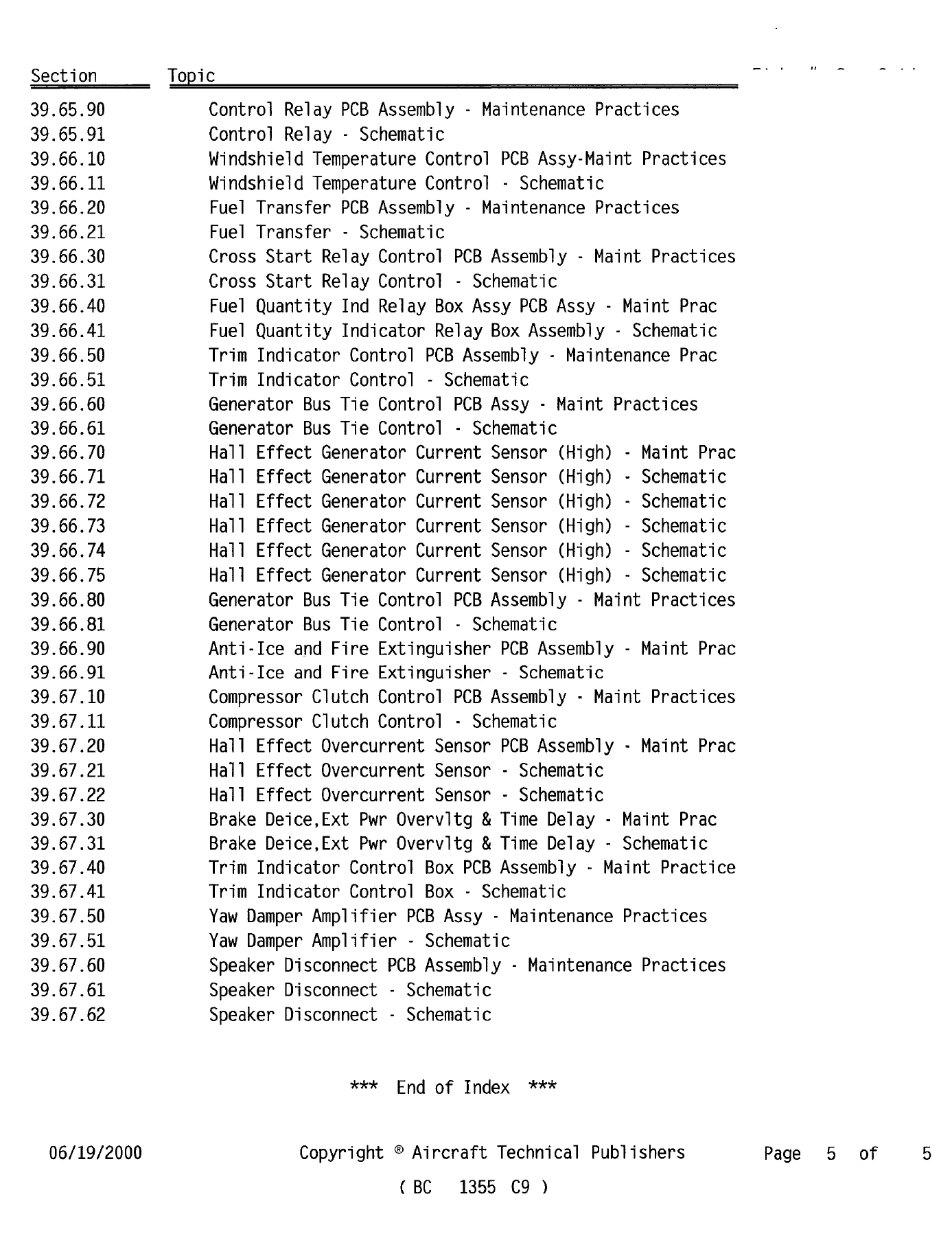
- Sections 39.65.90 to 39.65.91: Control Relay PCB Assemblies[cite: 1]
- Sections 39.66.10 to 39.66.11: Windshield Temperature Control PCB Assemblies[cite: 1]
- Sections 39.66.20 to 39.66.21: Fuel Transfer PCB Assemblies[cite: 1]
- Sections 39.66.30 to 39.66.31: Cross Start Relay Control PCB Assemblies[cite: 1]
- Sections 39.66.40 to 39.66.41: Fuel Quantity Indicator Relay Box Assemblies[cite: 1]
- Sections 39.66.50 to 39.66.51: Trim Indicator Control PCB Assemblies[cite: 1]
- Sections 39.66.60 to 39.66.81: Generator Bus Tie Control PCB Assemblies[cite: 1]
- Sections 39.66.70 to 39.66.75: Hall Effect Generator Current Sensor (High) PCB Assemblies[cite: 1]
- Sections 39.66.90 to 39.66.91: Anti-Ice and Fire Extinguisher PCB Assemblies[cite: 1]
- Sections 39.67.10 to 39.67.11: Compressor Clutch Control PCB Assemblies[cite: 1]
- Sections 39.67.20 to 39.67.22: Hall Effect Overcurrent Sensor PCB Assemblies[cite: 1]
- Sections 39.67.30 to 39.67.31: Brake Deice, External Power Overvoltage, and Time Delay PCB Assemblies[cite: 1]
- Sections 39.67.40 to 39.67.41: Trim Indicator Control Box PCB Assemblies[cite: 1]
- Sections 39.67.50 to 39.67.51: Yaw Damper Amplifier PCB Assemblies[cite: 1]
- Sections 39.67.60 to 39.67.62: Speaker Disconnect PCB Assemblies[cite: 1]
- Component Reference Indices: Alphabetical Index, 52-page Reference Designator Index, and Part Number Cross-Reference Index[cite: 1]
By compiling detailed component breakdowns, board layout figures, and full operational schematics into an organized ATA-indexed format, this manual gives line technicians and bench repair specialists the exact electrical data required to isolate card-level faults, test individual solid-state relays, replace damaged integrated circuits, and verify system airworthiness[cite: 1].
Airframe Zone Breakdown & Fleet Model Effectivity
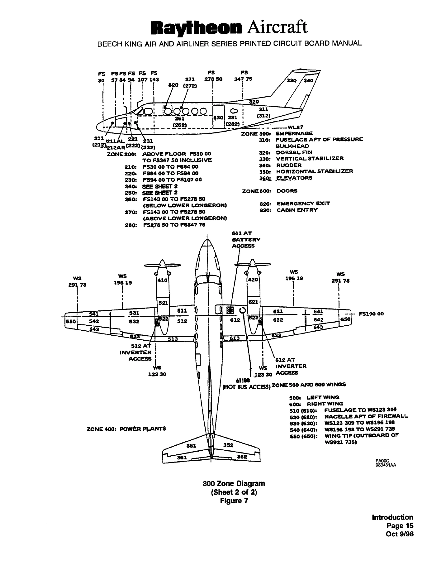
This technical publication supports a wide variety of turboprop corporate and regional airline aircraft produced under the Beechcraft and Raytheon banners[cite: 1]. To streamline equipment location and physical card access, the document contains comprehensive airframe zone diagrams mapping fuselage stations (FS), water lines (WL), and wing stations (WS)[cite: 1]:
- Beechcraft King Air 90 Series & F90: Zone diagrams detailing radome and lower floor stations (FS 30.00 to FS 298.00), cabin zones, empennage, wing stations (WS 99.616 to WS 266.735), and crew subpanels[cite: 1].
- Beechcraft King Air 200, B200, 200T, B200T, B200 (1300) HDC: Full fuselage breakdown (FS 30.00 to FS 347.75), main wing stations out to WS 291.735, power plant nacelles, inverter access panels (512AT, 612AT), and hot bus access doors (611BB)[cite: 1].
- Beechcraft King Air Cargo Variants (200C, 200CT, B200C, B200CT): Structural station layouts including cargo door framing (FS 251.75 to FS 274.50), cockpit subpanels, and wing tip tank wiring architectures[cite: 1].
- Beechcraft King Air 300 & B300 (Super King Air 350): Extended structural zone maps covering FS 0.00 ref through FS 381.75, main spar stations (FS 204.40), rear spar stations (FS 240.00), and cockpit flight deck instrumentation consoles[cite: 1].
- Beechcraft Airliner 99 & C99 Series: Passenger and commuter airframe zone distributions (FS 6.50 to FS 367.50), belly cargo pod bays (Zones 910 to 940), and wing break stations[cite: 1].
- Beechcraft 1900, 1900C, and 1900D Regional Airliners: Extended passenger cabin station mapping (FS 30.00 to FS 557.50), aft baggage/passenger doors, flight deck pedestal panels, and forward avionics bays[cite: 1].
Component Identification & Schematic Symbology
Every printed circuit card covered in the manual features an exhaustive equipment list matched to circuit reference designators[cite: 1]. Technicians can pinpoint specific resistors (R), capacitors (C), diodes and transient voltage suppressors (CR), transistors (Q), integrated circuits and operational amplifiers (U), relays (K), connectors (J), and voltage regulators (VR) directly on circuit diagrams and board layouts[cite: 1]. The included electrical symbols charts outline standard graphical representations for push-pull circuit breakers, unidirectional and bidirectional zener diodes, SCRs, non-saturating transformers, and multiple switch actuation types (pressure, vacuum, and temperature-actuated switches), ensuring exact schematic interpretation during bench testing[cite: 1].
Professional Capability & Instant Digital Delivery
Owning the Beechcraft King Air and Airliner Series Printed Circuit Board Manual P/N 98-39117F equips your avionics repair shop or corporate flight department with the exact manufacturer engineering data necessary to test, troubleshoot, and return circuit boards to airworthy condition[cite: 1]. Rather than replacing costly board assemblies blind or relying on generalized wiring diagrams, technicians can perform component-level bench diagnostics using proper voltage references, signal pathways, and verified schematic wiring[cite: 1]. Delivered as an instant high-quality PDF download immediately upon checkout, this digital manual eliminates shipping transit times and can be viewed on desktop computers, workshop laptops, or mobile tablets in the hangar or at the test bench, with full printing capabilities for physical bench work[cite: 1].


Reviews
There are no reviews yet.