
Claas Ares 806 Technical Support Manual – Complete Tractor Workshop Repair Guide
Original price was: $39.95.$24.95Current price is: $24.95.
Complete 1271-page Claas Ares 806 Technical Support Manual covering engine, gearbox, rear axle, hydraulics, electrics, electronics, cab and front PTO. Publication 60 05 030 493 – 09.2004.
Description
Claas Ares 806 Technical Support Manual – Complete Tractor Workshop Repair Guide
This Claas Ares 806 Technical Support Manual is a comprehensive workshop repair guide covering every major mechanical, hydraulic, electrical and electronic system on the Ares 806 tractor. From the DPS 6068 HRT engine through the GBA 10 and GBA 31 Full Powershift gearboxes, GPA 30 and GPA 40 rear axles, closed-centre hydraulic circuits and the full suite of electronic control systems, this Claas Ares 806 Technical Support Manual delivers the procedures, specifications, diagnostic flowcharts and tightening torques required to service and repair the machine correctly.
File Details
- Manual type: Technical Support Manual / Workshop Repair Guide
- Brand: Claas
- Model: Ares 806
- Publication number: 60 05 030 493
- Publication date: 09.2004
- Language: English
- Page count: 1271
- File format: PDF
Chapters Covered
Engine
- A0 – Injection Sheet Checking Procedure: Visual checks, engine oil level, hydraulic/transmission oil level, battery, coolers, diesel filters, air filter, turbocharger pressure, hydraulic pressure, dynamometer fitting, PTO test conditions, measurement sheet
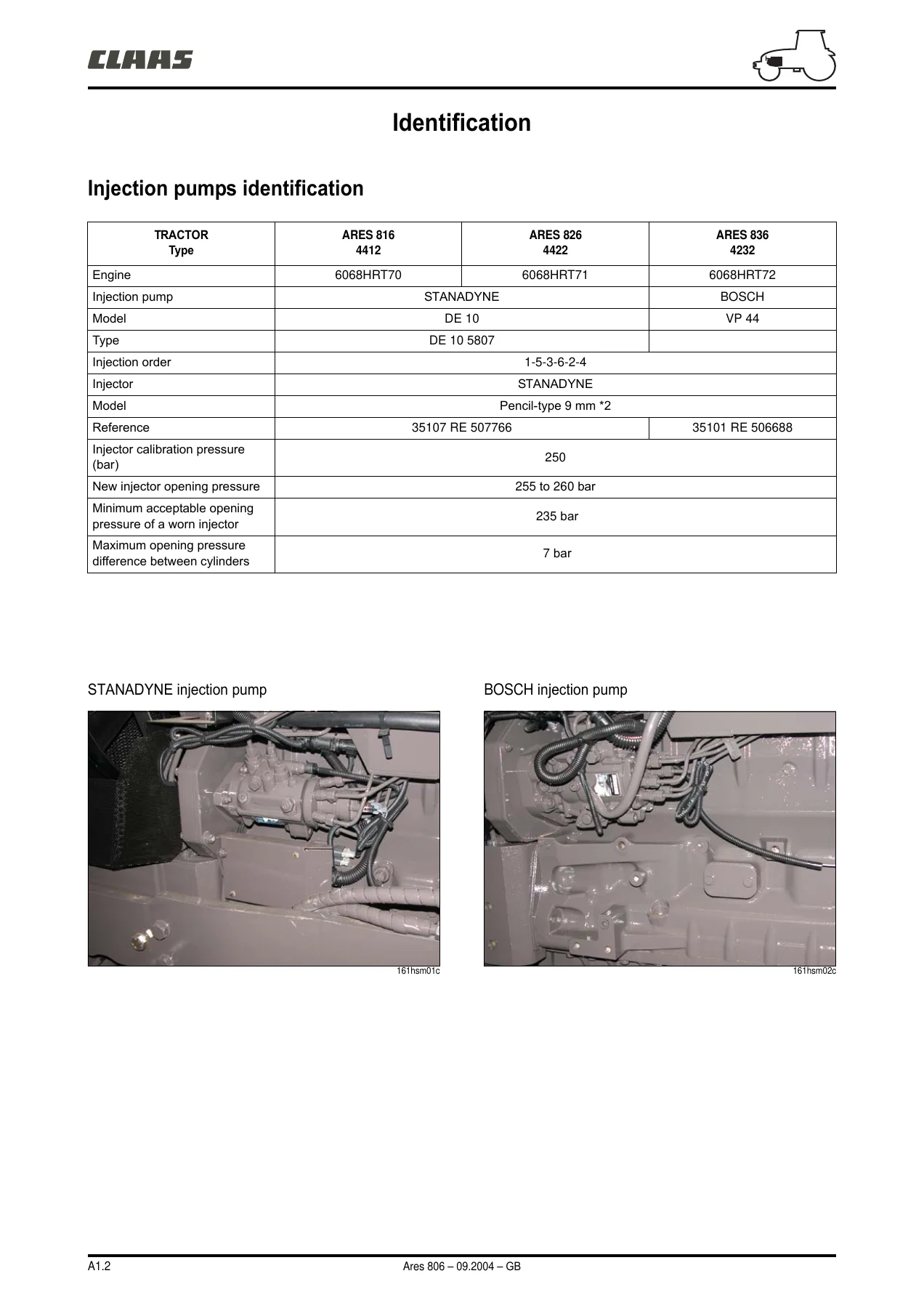
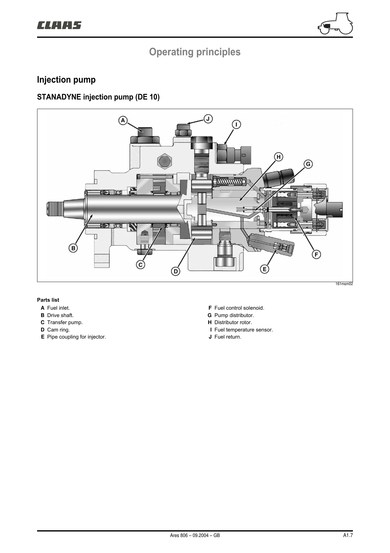
- A1 – Injection Feed: Injection pump identification (STANADYNE DE 10, BOSCH VP 44), tightening torques, pre-filter, fuel filter, injection pump operation, injectors, sensor locations, accelerator control adjustment, injector adjustment, supply pressure check, fuel filter replacement, injection system bleeding, injection pump removal/refitting, diagnostics
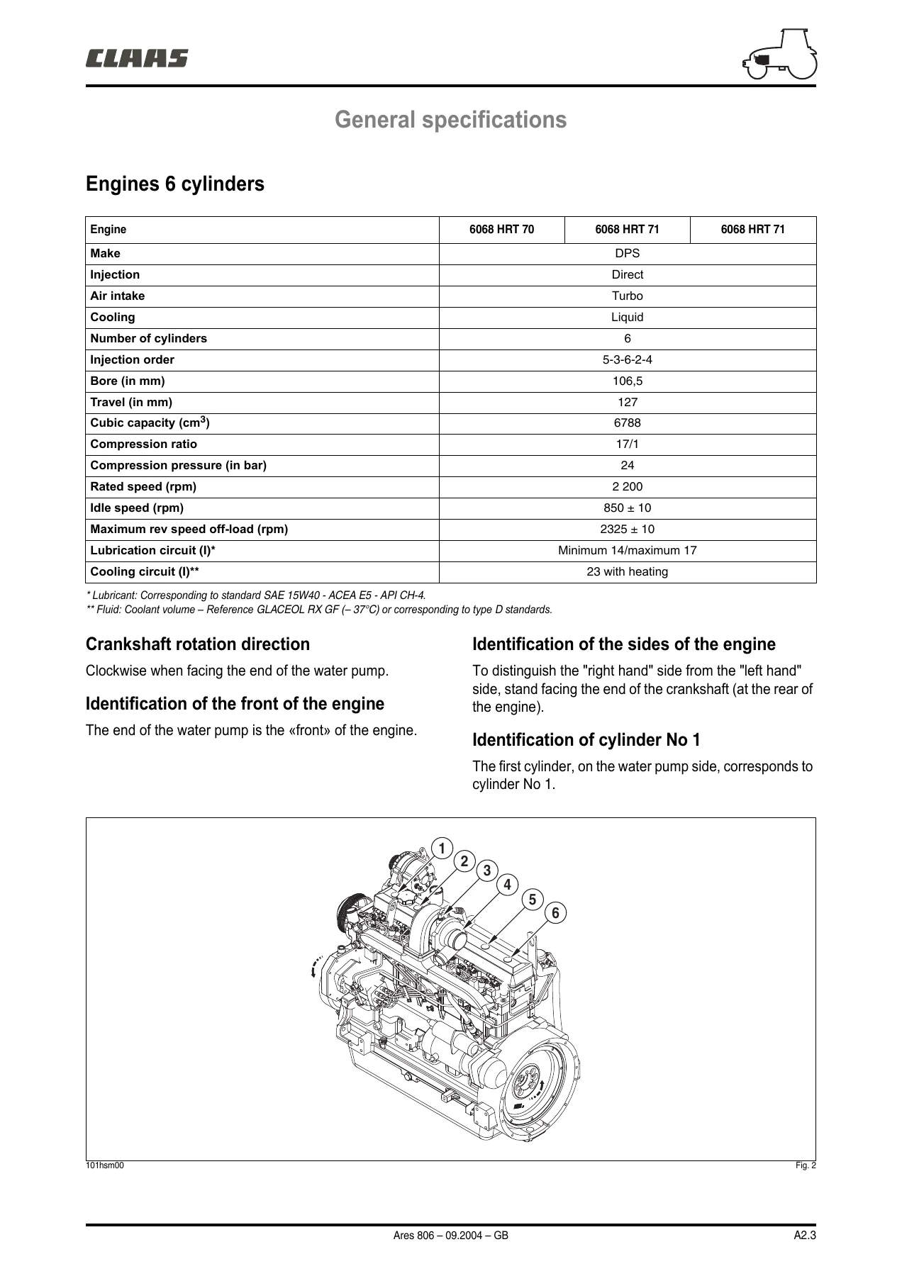
- A2 – Engine TIER II: Engine identification (DPS 6068 HRT 70/71/72), general specifications, dimensional specifications (cylinder head, valves, cylinder block, liners, pistons, connecting rods, crankshaft, camshaft, distribution, lubrication, cooling, turbocharger), tightening torques, compression check, oil pressure check, valve lift check, valve clearance adjustment, turbocharger pressure check, belt tensioner check, viscous fan coupling check, engine removal/refitting, cylinder head overhaul, camshaft, cylinder block, liners, pistons and connecting rods, crankshaft, bearings, flywheel, front bearing seal, balancer shafts, lubrication, cooling, turbocharger, diagnostic sheets, tools
Gearboxes
- B1 – GBA 10 Gearbox: General specifications, transmission kinematics, GTA 1041/1042/1044 Overdrive diagrams, removal/refitting procedure, tightening torques, Revershift operation, front clutch, rear clutch, Quadrishift unit, gearshift cover, guide rods, output shaft, input shaft, countershaft, crawler speeds
- B2 – GTA 1040 and GPA 30 Low-Pressure Hydraulic Circuit: LS 100 l/min circuit, LS 110 l/min circuit, hydraulic system, gearbox and rear axle lubrication, axle tube lubrication, distribution valve, Revershift and Quadrishift control, independent lubrication, solenoid valve checks, measurement and checking points, inspection results sheets
- B3 – GBA 31 Full Powershift Gearbox: General characteristics, transmission system description, gearbox arrangement, operation and power transmission, input shaft seal replacement, gearbox removal, tightening torques
- B4 – GBA 31 Low-Pressure Hydraulic Circuit: Operation, characteristics, transmission hydraulic circuit, oil filter, thermostatic valve, Gerotor pump repair, pressure control valve, proportional solenoid valve, discharge valve, measurement and checking points, inspection results sheet, tools
Rear Axles and Brakes
- C1 – GPA 40 Rear Axle: Tightening torques, GPA 40 drive pinion, 5″ differential, ND axle tubes, HD and HD+ axle tubes, HDE axle tubes, PTO clutch, PTO upper shaft, PTO lower shaft, proportional PTO, tools
- C2 – GPA 30 Rear Axle: Tightening torques, GPA 30 drive pinion, 5″ differential, PTO clutch, PTO upper shaft, PTO lower shaft, crawler gears, tools
- C3 – Service Brakes: Technical specifications, brake pistons and seals, boosters and master cylinders, bleeding the brake circuit, closed-centre hydraulic circuit checks
- C4 – Automatic Brake, Park Lock and Handbrake: Operating principles, control unit, brake mechanism, removal/refitting, basic parking brake adjustment, Park Lock general and schematic, safety switch, handbrake casing and control adjustment, brake disc wear diagnostics, tools
Front Axles
- D1 – Front Axle: General characteristics, drive chain, tightening torques, wheel alignment, steering cylinder, reduction gear and wheel hub, wheel pivot, angle sensor, bevel gear and differential, pinion protrusion distance, preload and backlash, hydraulic checks
- D2 – Proactiv Front Axle: General characteristics, tightening torques, wheel alignment, steering cylinder, epicyclic reduction gear, wheel hub, wheel pivot and upper arm, suspension cylinder, torsion bar, lower arm, universal shafts, suspension sensors, calibration, bevel gear and differential, suspension control unit, hydraulic and electric checks, diagnostics
- D3 – GPA 30 and GPA 40 4WD PTO Housing: General, cross-sectional views, exploded views, clutch removal/refitting, shaft shimming, solenoid valve checks, hydraulic checks, tools
Hydraulics
- E1 – Closed Centre Hydraulics (110 l/min): Characteristics, hydraulic circuit diagrams (Quadrishift and Full Powershift), component layouts, GPA 40 and GPA 30 rear axle sectional views, right-hand cover, priority units, variable displacement pump, left-hand cover, booster pump, spool valves, linkage spool valve, auxiliary spool valves, steering unit OSPQ 100/160 LS, measurement and checking points, inspection results sheets
- E2 – Closed Centre Hydraulics (100 l/min): Characteristics, general hydraulic circuit diagram, Quadrishift transmission circuit, right-hand cover, brake valve (BOSCH and SNR), priority unit, pressure limiter, left-hand cover, steering pump, measurement and checking points, inspection results sheets, tools
Electrical and Electronic Systems
- F – Electricity: Item list, wiring and general lists, schematic diagrams by function, connector and harness tracking, tools
- G1 – Instrument Panel: Operating principles, indicator light allocation, warning lights, input/output by function, connectors JX1 and JX2, transmission oil pressure sensor, blockage indicator, engine oil pressure sensor, transmission oil temperature sensor, speed sensors, connector removal/refitting, calibration
- G2 – TCE 15/25 and TCE 15 T Electronic Lift: Description, software version access, lift operating conditions, error codes, connections, position sensor on GPA 30 and GPA 40 axles, draft sensor, theoretical forward speed sensor, radar, lift spool valve solenoid valves
- G3 – Transmission/Axle Control: Drivetronic III component locations, shuttle reverser lever characteristics, range and declutching control, clutch pedal switches, Quadrishift II and Quadractiv controls, solenoid valves, pressure switches, speed sensors, temperature sensor, TOC/BOC and angle detector adjustment, static clutch calibration, calibration procedure adjustment, input/output by function, steering angle calibration, general schematic diagram, Drivetronic V, Full Powershift component locations and layout
- G4 – Engine Management: DE 10 pump components and sensors, characteristics, accelerator detector adjustment, diagnostic harness, VP 44 pump components and sensors, schematic diagram, accelerator detector adjustment, diagnostic harness
- G5 – Infotrac and ISO Socket: Functions of the on-board computer, operating principles, use, removal/refitting, electrical checks, ISO socket, ISO unit, external temperature probe, schematic diagram, connector wire functions, forward speed calibration, maintenance function
- G6 – Electropilot: Controls, joystick connections, DC power switch connections, module connections, electrohydraulic spool valve (DEH), removal/refitting, control handle, safety solenoid valve check, control pressure check, inspection results sheet, tools
- G7 – Win Metadiag Manual: Connecting Win Metadiag, engine application, SPN and FMI codes, DE 10 and VP 44 pump diagnostics, transmission application (Drivetronic and Full Powershift), rear axle application (GPA 41/42/43), rear lift application (TCE 15/25 and TCE 15 T), dashboard application, Electropilot application
Cab
- H1 – Cab Lift: Identification, right and left side operation locations, full cab removal safety measures, sling specifications, removal operations 1 to 21, refitting, tightening torques, adjustments, roof removal/refitting
- H2 – Heating/Air Conditioning: Characteristics, operating principle diagram, control panel, engine layout, cab layout, heating radiator unit and fans, heating radiator, diagnostics troubleshooting guide
- H3 – Bonding the Windows: Safety warnings, equipment list, special instructions, removal, preparing windscreen before primer, applying primer, preparing two-pack sealant, replacing the ploughing window, tools
Lift, Front PTO and Pneumatic Braking
- J1 – Lift and Front Power Take-Off: Front lift characteristics, exploded views of 3 500 and 6 600 daN front lifts, tightening torques, cylinder pressure check, front PTO characteristics, exploded view of front PTO assembly, unit exploded view, removing PTO housing, clutch exploded view, removing/refitting clutch, clutch feed pressure check, inspection results sheets
- J2 – Pneumatic Braking: How it works, measurement and checking points, with engine running and trailer connected (no brakes, service brakes applied, hand brake applied), main components (pneumatic circuit layout on GTA 3130, compressor, pressure regulator, tank, trailer control valve, solenoid valve, principal control valve), bleeding hydraulic and pneumatic trailer braking system, tools
What This Manual Covers
The Claas Ares 806 Technical Support Manual is a complete workshop reference compiled from the manufacturer’s technical documentation. It spans the full machine: engine mechanical and fuel injection systems, transmission and gearbox overhaul for both GBA 10 and GBA 31 Full Powershift units, rear axle and front axle rebuild procedures, closed-centre hydraulic circuits for both 100 l/min and 110 l/min configurations, the complete electrical system with wiring schematics and connector tracking, and the electronic control architecture including Drivetronic, TCE lift control, Electropilot, Infotrac and Win Metadiag diagnostics. The cab section covers removal, heating and air conditioning service, and window bonding procedures. The front lift, front power take-off and pneumatic braking chapters complete the coverage.
Every chapter includes the relevant specifications, tightening torques, measurement and checking points, and inspection results sheets where applicable. Diagnostic flowcharts are provided for engine start-up defects, irregular operation, smoke emission and cylinder head seal failures. The transmission and hydraulic sections include detailed exploded views, sectional diagrams and adjustment procedures for clutches, synchronisers, bearings, shafts and valve blocks.
Why This Manual Matters
Working on a modern agricultural tractor without correct procedures and specifications risks damage to precision components, incorrect assembly and costly rework. This Claas Ares 806 Technical Support Manual gives the technician the exact tightening torques, clearances, preloads, pressures and adjustment values needed for each system. The diagnostic flowcharts and error code tables enable efficient fault-finding on the electronic systems, while the step-by-step removal and refitting procedures with exploded views reduce the risk of assembly errors. The hydraulic circuit diagrams and pressure check procedures allow accurate testing and repair of the closed-centre systems. The electrical schematics and connector tracking help trace faults through the wiring harness.
Sales Close
IMAGES PREVIEW
Whether you are a professional agricultural mechanic, a workshop technician or a knowledgeable owner undertaking your own repairs, this Claas Ares 806 Technical Support Manual provides the depth of information needed to carry out major overhauls, routine maintenance and diagnostic work with confidence. The manual enables engine rebuilds, gearbox overhauls, axle repairs, hydraulic system service, electrical fault diagnosis and electronic system calibration on the Ares 806. All content is delivered as an instant PDF download, ready to view on any device and printable for use in the workshop. No shipping, no waiting—access the complete 1271-page Claas Ares 806 Technical Support Manual immediately after purchase.
Reviews
There are no reviews yet.