★ TRUSTED BY 321,897+ PROFESSIONALS WORLDWIDE
🏢
Trusted Business
Verified & Licensed
🛡️
Virus Free Files
100% Safe Downloads
🔒
Secure Payment
SSL Protected
Instant Delivery
Available Immediately
Sale!

Claas Ares 806 Workshop Manual 2004 – Complete Tractor Repair & Service PDF

Original price was: $44.95.Current price is: $27.95.

Complete 1271-page Claas Ares 806 workshop manual covering engine, transmission, rear axle, front axle, hydraulics, electrical, electronics, cab and implements. Publication 60 05 030 493, September 2004.

Instant PDF Download
Available immediately
💾
Save to Your Device
Download & keep forever
🛡️
Antivirus Scanned
100% virus-free
🌍
Trusted Worldwide
175,000+ customers

Description

Claas Ares 806 Workshop Manual – Complete Repair & Service PDF

The Claas Ares 806 Workshop Manual 2004 – Complete Tractor Repair & Service PDF is the full technical documentation set for the Ares 806 tractor, published under reference 60 05 030 493 in September 2004. At 1271 pages, this workshop manual covers every major system on the machine: engine, gearbox, rear axle, front axle, hydraulics, electrical system, electronic controls, cab and implement interfaces. Whether you are servicing a clutch pack, diagnosing a hydraulic fault, rebuilding a cylinder head, or tracing a wiring issue, the procedures and specifications in this Claas Ares 806 repair manual are the ones the workshop relies on.

File Details

  • Manual type: Workshop / repair / service manual
  • Brand: Claas
  • Model: Ares 806
  • Publication number: 60 05 030 493
  • Edition / date: September 2004 (09.2004)
  • Language: English
  • Page count: 1271
  • File format: PDF

Chapters Covered

  • A – Engine: A0 injection sheet checking procedure, A1 injection feed, A2 Engine Tier II — general specifications, dimensional specifications, tightening torques, checks and adjustments, removal and refitting, diagnostic sheets, engine tools.
  • B – Gearbox: B1 GBA 10 gearbox, B2 GTA 1040 and GPA 30 low-pressure hydraulic circuit, B3 GBA 31 Full Powershift gearbox, B4 GBA 31 low-pressure hydraulic circuit.
  • C – Rear Axle: C1 GPA 40 rear axle, C2 GPA 30 rear axle, C3 service brakes, C4 automatic brake, park lock and handbrake.
  • D – Front Axle: D1 front axle, D2 Proactiv front axle, D3 GPA 30 and GPA 40 4-wheel drive power take-off housing.
  • E – Hydraulics: E1 closed centre hydraulics (110 L/min), E2 closed centre hydraulics (100 L/min).
  • F – Electricity: wiring and general lists, schematic diagrams according to functions, harness and connector paths.
  • G – Electronics: G1 instrument panel, G2 TCE 15/25 and TCE 15 T electronic lift, G3 transmission/axle control, G4 engine management, G5 Infotrac and ISO socket, G6 Electropilot, G7 Win Métadiag manual.
  • H – Cab: H1 cab lift, H2 heating/air conditioning, H3 bonding the windows.
  • J – Implements: J1 lift and front power take-off, J2 pneumatic braking.

IMAGES PREVIEW

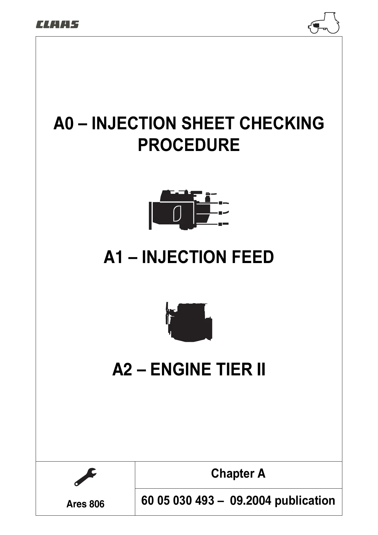
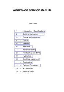
Claas Ares 806 Workshop Manual 2004 – Complete Tractor Repair & Service PDF — PDF page 2 preview
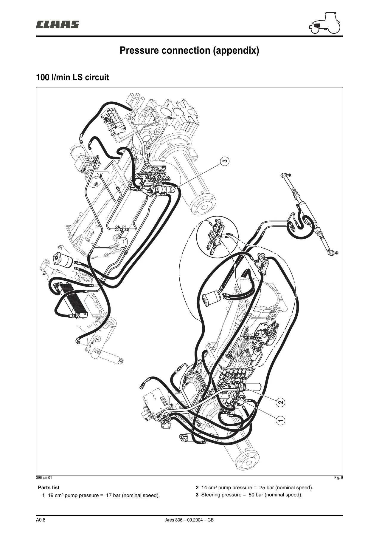
Claas Ares 806 Workshop Manual 2004 – Complete Tractor Repair & Service PDF — PDF page 62 preview
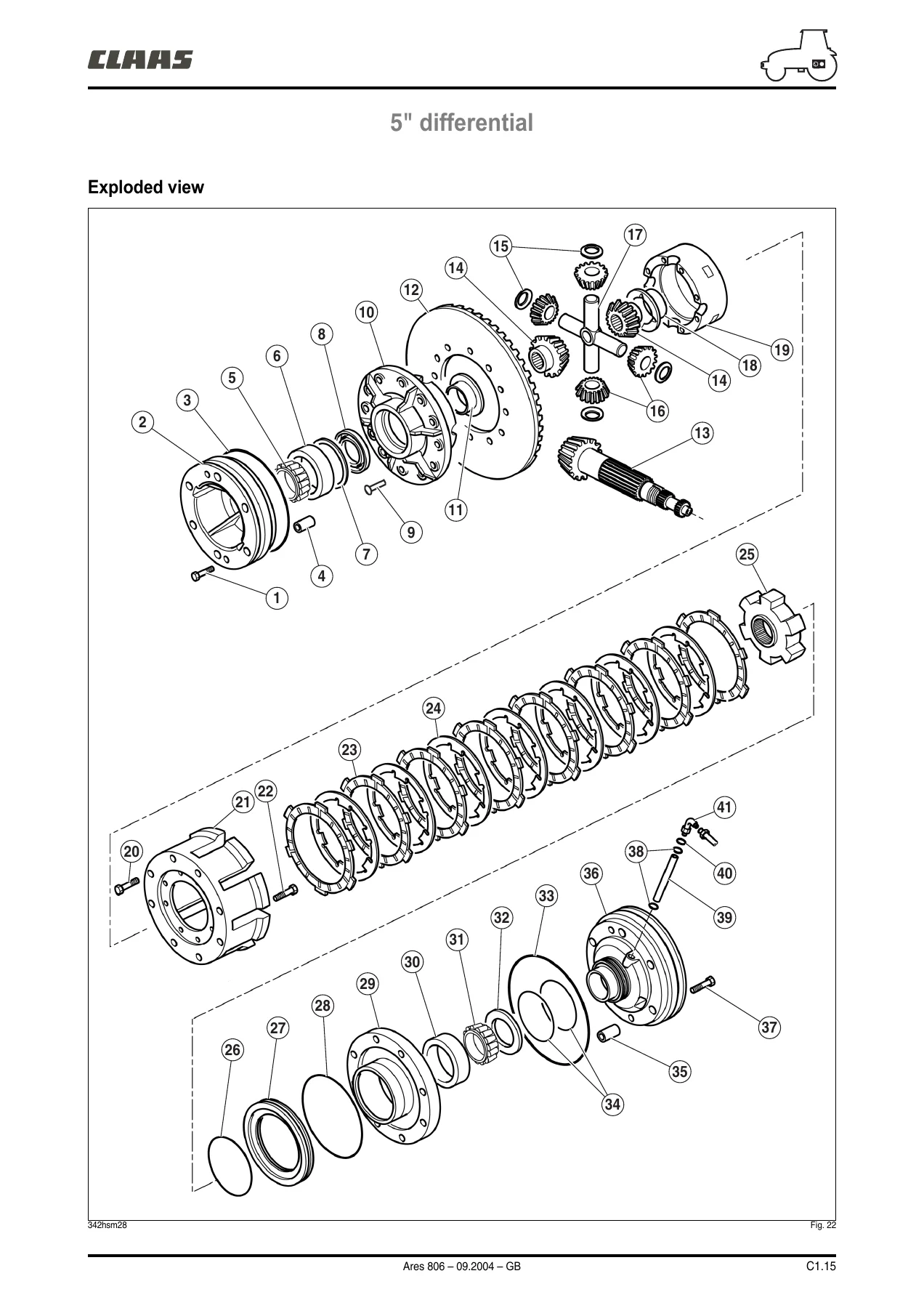
Claas Ares 806 Workshop Manual 2004 – Complete Tractor Repair & Service PDF — PDF page 353 preview

This Claas Ares 806 service manual gives you the complete picture of the machine’s mechanical and electronic architecture. The engine chapter alone covers the Tier II DPS 6068 engine family with dimensional specifications for cylinder head, valves, cylinder block, liners, pistons, connecting rods, crankshaft, camshaft, lubrication, cooling and turbocharger — plus full removal and refitting procedures, compression checks, valve clearance adjustment, viscous fan coupling testing and diagnostic flow charts. The transmission chapters document the GBA 10 and GBA 31 Full Powershift gearboxes, including clutch pack overhaul, epicyclic gear set assembly, guide rod adjustment, output shaft, input shaft and countershaft removal and shimming, plus the low-pressure hydraulic circuits that control them. The rear axle chapters cover the GPA 30 and GPA 40 axles in detail: drive pinion protrusion adjustment, differential case shimming, backlash setting, axle tube variants (ND, HD, HD+, HDE), power take-off clutch and shaft overhaul, and proportional PTO systems. The front axle chapters address the 20.29, 20.29-3, 20.43, 20.43-2, 20.43 SI, 20.43 SI-2 and 20.43 SI-3 rigid axles, including wheel pivot removal, epicyclic reduction gear, bevel gear and differential adjustment, and the Proactiv suspended front axle with its hydraulic control unit. The hydraulics chapters document both the 110 L/min and 100 L/min closed-centre systems, with circuit diagrams, component layouts, pump checks, spool valve adjustments and pressure testing. The electrical chapters provide wiring lists, harness routing, connector paths and functional schematics for every circuit on the tractor. The electronics chapters cover the instrument panel, electronic lift (TCE 15/25 and TCE 15 T), transmission and axle control (Drivetronic), engine management (DE 10 and VP 44 pumps), Infotrac on-board computer, ISO socket, Electropilot joystick control and the Win Métadiag diagnostic software. The cab and implement chapters round out the manual with cab lifting, heating and air conditioning, glass bonding, front lift, front PTO and pneumatic braking.

What This Manual Enables You to Do

With the Claas Ares 806 workshop manual PDF, you can carry out the same procedures a trained technician would follow in a workshop. That includes engine overhaul — removing the cylinder head, extracting liners, replacing pistons and rings, setting valve clearances, checking compression, adjusting injectors, removing and refitting the injection pump (both Stanadyne DE 10 and Bosch VP 44 types), and diagnosing starting or running faults using the diagnostic flow charts. On the transmission side, you can overhaul the GBA 10 gearbox, rebuild the Revershift clutches, strip and reassemble the Quadrishift unit, adjust the guide rods and forks, remove and refit the output shaft, input shaft and countershaft, and shim the tapered roller bearings correctly. The rear axle chapters let you set drive pinion protrusion, adjust differential backlash, shim the differential case bearings, replace axle tube bearings and seals, and service the PTO clutch and shafts. The front axle chapters support wheel pivot removal, epicyclic reduction gear overhaul, bevel gear and differential adjustment, suspension cylinder and torsion bar work, and steering angle sensor calibration. The hydraulics chapters give you the pressure and flow values needed to test the variable displacement pump, boost pressure, standby pressure, spool valve flow rates and steering pressures. The electrical and electronic chapters provide the wiring diagrams, connector pinouts and diagnostic procedures to trace faults in the instrument panel, transmission control, engine management, lift control and Electropilot systems.

Complete PDF Bookmark Tree

Complete Bookmarks

The complete bookmarks in the “Claas Ares 806 Workshop Manual 2004 – Complete Tractor Repair & Service PDF” are as follows:

Contents.pdfp. 1
Contents.pdfp. 1
SYMBOLS
A0 – INJECTION SHEET CHECKING PROCEDURE
A1 – INJECTION FEED
A2 – ENGINE TIER II
B1 – GBA10 GEARBOX
B2 – GTA 1040 AND GPA 3 0 LOW-PRESSURE HYDRAULIC CIRCUIT
B3 – GBA 31 FULL POWERSHIFT GEARBOX
B4 – GBA31 LOW-PRESSURE HYDRAULIC CIRCUIT (FULL POWERSHIFT)
C1 – GPA 40 REAR AXLE
C2 – GPA 30 REAR AXLE
C3 – FOOT BRAKE
C4 – AUTOMATIC BRAKE, PARK LOCK AND HANDBRAKE
D1 – FRONT AXLE
D2 – PROACTIV FRONT AXLE
D3 – GPA30 ANDGPA40 4-WHEEL DRIVE POWER TAKE-OFF HOUSING
E1 – CLOSED CENTRE HYDRAULICS (110L/MIN)
E2 – CLOSED CENTRE HYDRAULICS (100L/MIN)
F1 – ELECTRICITY
F2 – HARNESS AND CONNECTOR PATHS
G1 – INSTRUMENT PANEL
G2 – TCE15/25 ANDTCE15T ELECTRONIC LIFT
G3 – TRANSMISSION/AXLE CONTROL
G4 – ENGINE MANAGEMENT
G5 – INFOTRAC AND ISO SOCKET
G6 – ELECTROPILOT
G7 – WIN METADIAG© ARES 806 MANUAL
H1 – CAB LIFT
H2 – HEATING/AIR CONDITIONING
H3 – BONDING THE WINDOWS
J1 – LIFT AND FRONT POWER TAKE-OFF
J2 – PNEUMATIC BRAKING
EXIT
SOM_A_GB.pdfp. 2
A0 – INJECTION SHEET CHECKING PROCEDURE
A1 – INJECTION FEED
A2 – ENGINE TIER II
MR 806 CONTENTS
SOM_B_GB.pdfp. 8
B1–GBA10 GEARBOXp. 8
B2 – GTA 1040 AND GPA 3 0 LOW-PRESSURE HYDRAULIC CIRCUITp. 8
B3–GBA31 GEARBOX (FULL POWERSHIFT)p. 8
B4–GBA31 LOW-PRESSURE HYDRAULIC CIRCUIT (FULL POWERSHIFT)p. 8
MR 806 CONTENTS
SOM_C_GB.pdfp. 16
C1–GPA 40 REAR AXLEp. 16
C2–GPA 30 REAR AXLEp. 16
C3–FOOT BRAKEp. 16
C4–AUTOMATIC BRAKE, PARK LOCK AND HANDBRAKEp. 16
MR 806 CONTENTS
SOM_D_GB.pdfp. 23
D1–FRONT AXLEp. 23
D2–PROACTIV FRONT AXLEp. 23
D3–GPA30 ANDGPA40 4-WHEEL DRIVE POWER TAKE-OFF HOUSINGp. 23
MR 806 CONTENTS
SOM_E_GB.pdfp. 29
E1 – CLOSED CENTRE HYDRAULICS (110L/MIN)p. 29
E2 – CLOSED CENTRE HYDRAULICS (100L/MIN)p. 29
CONTENTS
SOM_F_GB.pdfp. 35
F1 – ITEM LISTWIRING AND GENERAL LISTSp. 35
F2 – HARNESS AND CONNECTOR PATHSp. 35
MR 806 CONTENTS
SOM_G_GB.pdfp. 41
G1–INSTRUMENT PANEL
G2–TCE15/25 ANDTCE15T ELECTRONIC LIFT
G3–TRANSMISSION/AXLE CONTROL
G4–ENGINE MANAGEMENT
G5–INFOTRAC AND ISO SOCKET
G6–ELECTROPILOT
G7–WIN MÉTADIAG©
MR 806 CONTENTS
SOM_H_GB.pdfp. 47
H1 CAB LIFTp. 47
H2 HEATING/AIR CONDITIONINGp. 47
H3 BONDING THE WINDOWS
MR 806 CONTENTS
SOM_J_GB.pdfp. 51
J1 – LIFT AND FRONT POWER TAKE-OFF
J2 – PNEUMATIC BRAKING
MR 806 CONTENTS
A to F.pdfp. 55
A0.pdfp. 55
A0 – INJECTION SHEET CHECKING PROCEDUREp. 55
Checking procedurep. 56
Measurement sheetp. 61
Pressure connection (appendix)p. 62
ARES 816 – H 4412p. 65
ARES 826 QUADRISHIFT – H 4422p. 67
ARES 826 FULL-POWERSHIFT – H 4322p. 69
ARES 836 – H 4432p. 71
MR 806 CONTENTS
A1.pdfp. 73
A1 – INJECTION FEEDp. 73
Identificationp. 74
Tightening torques (DE 10)p. 75
Tightening torques (VP 44)p. 76
Operating principlesp. 77
Checks/Adjustmentsp. 84
Removal/refittingp. 87
Diagnosticsp. 92
MR 806 CONTENTS
A2.pdfp. 97
A2 – ENGINE TIER IIp. 97
General specificationsp. 98
DIMENSIONAL SPECIFICATIONSp. 100
General specificationsp. 104
Tightening torquesp. 112
Checks/Adjustmentsp. 116
Removal/refittingp. 121
Diagnostic Sheetsp. 171
TOOLSp. 181
MR 806 CONTENTS
B1.pdfp. 189
B1–GBA10 GEARBOXp. 189
General specificationsp. 190
Tightening torquesp. 199
Main adjustmentsp. 202
REVERSHIFTp. 203
Front clutchp. 205
Rear clutchp. 211
Quadrishift unitp. 217
Gearshift coverp. 234
Guide rodsp. 238
Output shaftp. 242
Input shaftp. 247
Countershaftp. 253
Crawler speedsp. 257
MR 806 CONTENTS
B2.pdfp. 263
B2 GTA1040 AND GPA30 LOW-PRESSURE HYDRAULIC CIRCUITp. 263
LS 100l/min low-pressure circuit onGTA1040p. 264
LS 110l/min low-pressure circuit onGPA30p. 274
Low-pressure hydraulic componentsp. 279
Solenoid valve measurement and checking pointsp. 287
GBA10 distribution unit measurement and checking pointsp. 289
"Hydraulic inspection results" sheetp. 291
GBA10 lubrication measurement and checking pointsp. 292
"Hydraulic inspection results" sheetp. 293
LS 110l/min measurement and checking pointsp. 294
"Hydraulic inspection results" sheetp. 296
LS 100l/min measurement and checking pointsp. 297
"Hydraulic inspection results" sheetp. 299
MR 806 CONTENTS
B3.pdfp. 301
B3 GBA 31 FULL POWERSHIFT GEARBOXp. 301
Generalp. 302
Repairp. 313
MR 806 CONTENTS
B4.pdfp. 317
B4 FULL POWERSHIFT LOW PRESSURE HYDRAULIC CIRCUITp. 317
Generalp. 318
Repairp. 324
Measurement and checking pointsp. 328
"Inspection results" sheetp. 332
TOOLSp. 333
MR 806 CONTENTS
C1.pdfp. 339
C1 – GPA 40 REAR AXLEp. 339
Tightening torques and principal adjustmentsp. 341
GPA 40 drive pinionp. 344
5" differentialp. 351
ND axle tubesp. 363
HD etHD+ axle tubesp. 371
HDE axle tubesp. 379
GPA 40 power take-off clutchp. 387
GPA 40 power take-off upper shaftp. 392
GPA 40 power take-off lower shaftp. 401
Proportional power take-offp. 407
MR 806 CONTENTS
C2.pdfp. 413
C2 – GPA 30 REAR AXLEp. 413
Tightening torques and main adjustmentsp. 414
GPA 30 drive pinionp. 419
5" differentialp. 428
GPA 30 power take-off clutchp. 440
GPA 30 power take-off upper shaftp. 446
GPA 30 power take-off lower shaftp. 448
GPA 30 crawler gearsp. 454
MR 806 CONTENTS
C3.pdfp. 459
C3 – SERVICE BRAKESp. 459
Technical specificationsp. 460
Brake pistons and sealsp. 461
Boosters and master cylindersp. 465
Replacing the master cylindersp. 466
Bleeding the brake circuitp. 467
MR 806 CONTENTS
C4.pdfp. 475
C4–AUTOMATIC BRAKE, PARK LOCK AND HANDBRAKEp. 475
Automatic brakep. 476
Park Lockp. 488
Handbrakep. 498
TOOLSp. 503
MR 806 CONTENTS
D1.pdfp. 507
D1–FRONT AXLEp. 507
Descriptionp. 508
Removal/refittingp. 511
Disassembly prior to front axle operationsp. 514
Removal/refittingp. 515
Hydraulic measurement and checking pointsp. 530
"Hydraulic inspection results" sheetp. 531
MR 806 CONTENTS
D2.pdfp. 533
D2–PROACTIV FRONT AXLEp. 533
Descriptionp. 534
Removal/refittingp. 537
Disassembly prior to front axle operationsp. 540
Removal/refittingp. 541
Hydraulic measurement and checking pointsp. 580
"Hydraulic inspection results" sheetp. 582
Electric checksp. 583
Breakdown diagnosisp. 585
MR 806 CONTENTS
D3.pdfp. 587
D3–GPA30 ANDGPA40 4-WHEEL DRIVE POWER TAKE-OFF HOUSINGp. 587
Descriptionp. 588
Removing/refitting the housingp. 595
Solenoid valve measurement and checking pointsp. 599
Hydraulic measurement and checking pointp. 600
"Hydraulic inspection results" sheetp. 601
TOOLSp. 603
MR 806 CONTENTS
E1.pdfp. 611
E1CLOSED CENTRE HYDRAULICS(110l/min)p. 611
Descriptionp. 612
Removing/refitting the componentsp. 621
Hydraulic measurement and checking pointsp. 672
"Hydraulic inspection results" sheetp. 676
Hydraulic measurement and checking pointsp. 679
"Hydraulic inspection results" sheetp. 682
MR 806 CONTENTS
E2.pdfp. 683
E2 CLOSED CENTRE HYDRAULICS 100l/minp. 683
Descriptionp. 684
Removing/refitting the componentsp. 693
Hydraulic measurement and checking pointsp. 705
"Hydraulic inspection results" sheetp. 710
Hydraulic measurement and checking pointsp. 711
"Hydraulic inspection results" sheetp. 715
TOOLSp. 717
MR 806 CONTENTS
F1.pdfp. 719
F1 – ITEM LISTWIRING AND GENERAL LISTSp. 719
FUSE AND RELAY BOXp. 726
DE10 STARTING/CHARGING/PREHEATING CIRCUITp. 730
VP44 STARTING/CHARGING/PREHEATING CIRCUITp. 731
DIPPED HEADLIGHTS – HEADLIGHTS – HORN – SIDE LIGHTS – INSTRUMENT PANEL LIGHTp. 732
ROTATING BEACONSp. 733
FRONT WORK LIGHTSp. 734
REAR WORK LIGHTSp. 735
STOP LIGHTS – FRONT AXLE ENGAGEMENT – AIR BRAKE SYSTEM SOLENOID VALVE CONTROLp. 736
FLASHING LIGHTS AND WARNING LIGHTSp. 737
CIGAR LIGHTER – CLOCK – RADIO – CAB LIGHT AND SPOTp. 738
PNEUMATIC SEAT – FRONT POWER TAKE OFF CLUTCHp. 739
FRONT AND REAR WINDSCREEN WIPER / WASHERp. 740
INSTRUMENT PANEL VENTILATION AND AIR CONDITIONINGp. 742
INFOTRAC ON-BOARD COMPUTER / ISO SOCKETp. 744
FUEL GAUGE – ENGINE TEMPERATURE OIL PRESSURE – AIR FILTER BLOCKEDp. 746
HANDBRAKE – BRAKE FLUID LEVELp. 747
ENGINE SPEEDp. 748
INSTRUMENT PANEL CALIBRATION – DIAGNOSTIC SOCKET INSTRUMENT PANEL AND TCE 15Tp. 749
ELECTROPILOT/DRIVETRONIC/GTA 103-202/GPA 40 DIAGNOSTIC SOCKETp. 750
ELECTROPILOT/DRIVETRONIC/FPS DIAGNOSTIC SOCKETp. 751
25 A POWER SOCKETp. 752
TRANSMISSION HYDRAULIC PRESSURE – OIL FILTER BLOCKED (HP) – OIL FILTER BLOCKED (SUCTION)p. 753
THEORETICAL SPEEDp. 754
INSTRUMENT PANEL – REAR POWER TAKE-OFF SPEEDp. 755
TCE 15T LIFTp. 756
ELECTROPILOT (WITH TCE 15T)p. 760
LIFT TCE – 15/25/35/ RADARp. 762
ELECTROPILOT (WITH TCE 15/25/35)p. 764
GTA 103-202 – GPA 40 CLUTCH AND DRIVE CONTROLp. 766
AUTOMATIC HAND BRAKEp. 769
FPS CLUTCH AND DRIVE CONTROLp. 770
FPS PARK LOCKp. 773
QUADRISHIFT IIp. 774
QUADRACTIV GTA 103-202 – GPA 40p. 778
FPS QUADRACTIVp. 782
DE10 ENGINE CONTROLp. 786
VP44 ENGINE CONTROLp. 788
SUSPENDED FRONT AXLEp. 790
FRONT AXLE ENGAGING – DIFFERENTIAL AND REAR POWER TAKE OFFp. 792
OIL TEMPERATURE SENSORS – ENGINE SPEED – FORWARD SPEED – REAR POWER TAKE-OFF SPEED – REVERSER MODULE SPEED – DRIVETRONICp. 794
CROSS CONTROL WITH SOLENOID PILOTp. 795
CROSS CONTROLp. 796
DE10 CANp. 797
VP44 CANp. 798
MR 806 CONTENTS
F2.pdfp. 799
F2-HARNESS AND CONNECTOR PATHSp. 799
CONTENTSp. 800
1 – Instrument panel harnessp. 802
2 – Preheating control harnessp. 810
3/1 – Front harnessp. 810
3/2a – Front harnessp. 810
3/2b – Injection harnessp. 810
3/2c – Injection control harnessp. 810
4 – Front axle suspension control harnessp. 820
5 – Instrument panel / cab top harnessp. 822
5a – Cab top / front lights harnessp. 826
5b – Cab top / rear light harness with air conditioningp. 826
5c – Front and rear light harnessp. 830
6 – Rear harnessp. 834
7a – Closed centre circuit transmission harness – 110 litresp. 838
7b – Closed centre circuit transmission harness – 100 litresp. 838
7c – GTA 303 transmission link harnessp. 838
7d – GTA 303 transmission harnessp. 838
8a – GTA 103/202 – GPA 40 transmission control harnessp. 850
8b – Full Powershift transmission control harnessp. 850
8/1 – ISO socket harnessp. 850
8/2 – Quadrishift 2/Quadractiv/Full Powershift display harnessp. 850
9a – TCE 15/25/35 Control harnessp. 864
9b – TCE 15T Control harnessp. 868
9/1a – TCE 15/25/35 Harnessp. 872
9/1b – TCE 15T Harnessp. 876
9/2a – Cross control harness with Electropilotp. 880
9/2b – Cross control harnessp. 880
9/3 – Electrohydraulic spool valve control harnessp. 882
10 – On-board computer harnessp. 882
MR 806 CONTENTS
G Onwards.pdfp. 886
G1.pdfp. 886
G1 – INSTRUMENT PANELp. 886
Operating principlesp. 887
Characteristicsp. 889
Removal/refittingp. 905
Calibrationp. 906
MR 806 CONTENTS
G2.pdfp. 908
G2–TCE15/25 ANDTCE15T ELECTRONIC LIFTp. 908
Descriptionp. 909
Checks and adjustmentsp. 913
MR 806 CONTENTS
G3.pdfp. 924
G3–TRANSMISSION/AXLE CONTROLp. 924
Drivetronic IIIp. 925
Drivetronic Vp. 956
Full Powershiftp. 960
MR 806 CONTENTS
G4.pdfp. 978
G4–ENGINE MANAGEMENTp. 978
DE 10 Pumpp. 979
VP 44 Pumpp. 991
MR 806 CONTENTS
G5.pdfp. 1006
G5–INFOTRAC AND ISO SOCKETp. 1006
Descriptionp. 1007
Removal/refitting and electrical checksp. 1011
MR 806 CONTENTS
G6.pdfp. 1020
G6–ELECTROPILOTp. 1020
Descriptionp. 1021
Removal/refittingp. 1025
Measurement and checking pointsp. 1026
"Inspection results" sheetp. 1028
TOOLSp. 1030
MR 806 CONTENTS
G7.pdfp. 1034
G7 – WIN METADIAG© ARES 806 MANUALp. 1034
Connecting Win Métadiag©p. 1039
Engine applicationp. 1041
Transmission applicationp. 1141
Rear axle applicationp. 1171
Rear lift applicationp. 1174
Dashboard applicationp. 1181
Electropilot applicationp. 1184
MR 806 CONTENTS
H1.pdfp. 1192
H1 – CAB LIFTp. 1192
Descriptionp. 1193
Full cab removalp. 1196
Removal/refittingp. 1197
Refitting the cabp. 1206
Removing/refitting the roofp. 1208
MR 806 CONTENTS
H2.pdfp. 1210
H2 – HEATING/AIR CONDITIONINGp. 1210
Descriptionp. 1211
Removal/refittingp. 1215
Troubleshooting Guidep. 1226
MR 806 CONTENTS
H3.pdfp. 1228
H3 – BONDING THE WINDOWSp. 1228
Removal/refittingp. 1229
TOOLSp. 1238
MR 806 CONTENTS
J1.pdfp. 1242
J1 – LIFT AND FRONT POWER TAKE-OFFp. 1242
Front liftp. 1243
Measurement and checking pointsp. 1246
"Inspection results" sheetp. 1247
Front power take-offp. 1248
Measurement and checking pointsp. 1253
"Inspection results" sheetp. 1254
CONTENTS
J2.pdfp. 1256
J2 – PNEUMATIC BRAKINGp. 1256
How it worksp. 1258
Main componentsp. 1265
TOOLSp. 1270
MR 806 CONTENTS

Why the Correct Procedures and Specifications Matter

Modern agricultural tractors like the Ares 806 combine mechanical, hydraulic and electronic systems that interact in ways that are not always obvious. A transmission that slips may be suffering from a hydraulic pressure fault, a solenoid valve issue, a worn clutch pack or a calibration problem — and the diagnostic flow charts in this manual help you narrow down the cause before you start removing components. Torque values matter on components such as cylinder head bolts, connecting rod bolts, flywheel bolts and axle bearing retainers; the manual gives the exact tightening torques and angular tightening sequences. Shimming and preload settings on differentials, gearbox shafts and axle bearings determine how long the repaired assembly will last — get them wrong and a repair can fail in a matter of hours. The hydraulic test values tell you whether a pump is worn, a valve is sticking or a relief setting has drifted. And the electrical connector pinouts and wire markers let you test circuits methodically instead of guessing. Having the complete Claas Ares 806 service manual means you are working from the same information the dealer workshop uses, which reduces the risk of costly mistakes and repeat repairs.

Instant PDF Delivery – No Shipping, No Waiting

The Claas Ares 806 Workshop Manual 2004 is delivered as a PDF download. There is no physical book to ship and no waiting for delivery. You can download the file immediately after payment, save it to your computer, tablet or phone, and print the pages you need for the job at hand. The PDF format lets you keep the entire 1271-page manual on a device in the workshop, so you can search for a torque value, a wiring pinout or a diagnostic procedure without leaving the machine. Whether you are a professional technician, a farm owner maintaining your own Ares 806, or someone restoring a used tractor, this workshop manual gives you the complete technical documentation for the machine.
Reviews

There are no reviews yet.

Be the first to review “Claas Ares 806 Workshop Manual 2004 – Complete Tractor Repair & Service PDF”

What Our Customers Say

★★★★★ Live reviews from customers
Loading customer reviews...
0
    0
    Your Cart
    Your cart is emptyReturn to Shop
    🛒
    Recently Purchased
    🕒 verified order