
Massey Ferguson 6100 Series Tractors Workshop Service Manual – MF 6110 to 6190
Original price was: $37.95.$22.95Current price is: $22.95.
Workshop service manual for Massey Ferguson 6100 Series tractors MF 6110, 6120, 6130, 6140, 6150, 6160, 6170, 6180 and 6190, covering split procedures, clutch, gearbox, axles, PTO, hydraulics, electrics, Autotronic/Datatronic electronics and cab systems.
Description
Massey Ferguson 6100 Series Tractors Workshop Service Manual – MF 6110 to 6190
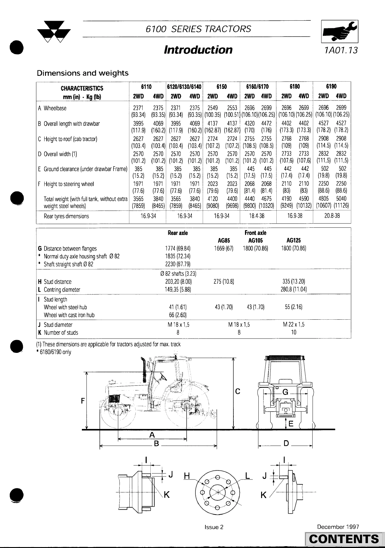
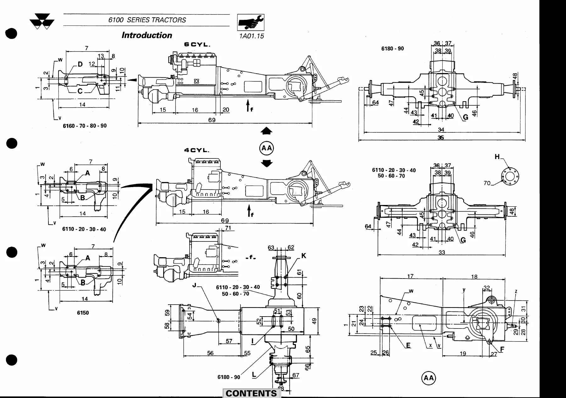
This Massey Ferguson 6100 Series Tractors Workshop Service Manual – MF 6110 to 6190 is the workshop-level repair book used to install, maintain and overhaul the 6100 range. It is written for distributors and dealers and sets out the removal, refitment, adjustment and test sequences needed to service the tractor as a complete machine. Pages carry the 6100 Series header, issue dates of February 1995 and December 1997 on revised specification sheets, and the part/section numbering system used throughout the book (for example 7C01-3).
Coverage runs across nine models in 2WD and 4WD form: MF 6110, MF 6120, MF 6130, MF 6140, MF 6150, MF 6160, MF 6170, MF 6180 and MF 6190. Perkins four- and six-cylinder engines are identified by model, output and PTO power, but full engine strip-down is not reproduced here. The engine chapter states that technical data, adjustments and removal/fitting of the power unit itself belong in the separate Perkins workshop manuals referenced as 1856562 M1 and 1646906 M1. What this volume does give is the tractor-side work that surrounds the engine: splitting, flywheel damper, clutch spacers, transmission, axles, PTO, open- and closed-centre hydraulics, electrics, electronic lift, Autotronic 2, Datatronic and cab air conditioning.
File Details
- Manual type: Workshop Service Manual
- Brand / models: Massey Ferguson 6100 Series – MF 6110, 6120, 6130, 6140, 6150, 6160, 6170, 6180, 6190
- Language: English
- Page count: 815
- File format: PDF
- Issue marking: Issue 1 February 1995; specification pages marked Issue 2 December 1997
Models, Engines and Capacities in This Book
The specification tables in the Massey Ferguson 6100 Series Tractors Workshop Service Manual – MF 6110 to 6190 list Perkins power units model by model. Four-cylinder tractors use Perkins 4.41 on the 6110 and 6120, 1004.4TLR on the 6130, 1004.4T2 on the 6140 and 1004-4THR2 on the 6150. Six-cylinder tractors use 1006-6 HR4 on the 6160, 1006-6 HR3 on the 6170, 1006-6TLR2 on the 6180 and 1006-THR2 on the 6190. Bore and stroke are given as 101.1 x 127 mm on the 4.41 engines and 100 x 127 mm on the 1000-series engines, with cubic capacities of 4100 cc (4.41), 4000 cc (four-cylinder 1000 series) and 6000 cc (six-cylinder). Maximum engine power DIN at 2200 rev/min runs from 51.5 kW on the 6110 to 95.6 kW on the 6190; corresponding PTO power DIN is 47 kW to 88.3 kW. Maximum torque figures range from 265 Nm to 530 Nm.
Valve clearances (cold) are 0.30 mm inlet and exhaust on the earlier four-cylinder layout and 0.20 mm inlet / 0.45 mm exhaust on the later grouping shown in the table. Idling speeds are listed as 750, 850 or 1000 rev/min depending on model, with a maximum no-load speed of 2350 or 2310 rev/min. Cooling is a centrifugal pump and pressurised radiator with a thermostat opening temperature of 82 degrees C. Fan drive is belt-driven on 6110-6150 (viscostatic noted on 6150) and viscostatic with a gear-driven water pump on 6160-6190. Belt deflection on the longest span is 19 mm on four-cylinder engines and 10 mm on six-cylinder engines.
Fluid capacities printed in the introduction include fuel tanks of 130 l (6110-6140) and 160 l (6150-6190); cooling systems of 17 l or 25 l; engine sumps of 7.4 l or 14.8 l; transmission/rear axle of 62 l or 68 l, with a note that 10 l may be added for steep-slope work; front axle assemblies of 6 l, 6.7 l or 9 l; and front final-drive units of 1 l, 1.2 l or 2 l each. The same chapter records 12-volt negative-earth electrics with two maintenance-free batteries and clutch-pedal safety start, hydrostatic steering with a double-acting central ram, oil-immersed single-disc brakes of 343 mm outside diameter, and Category 2 or 3 three-point lift with ram diameters of 57 mm, 66 mm or 73 mm according to model.
Chapters Covered
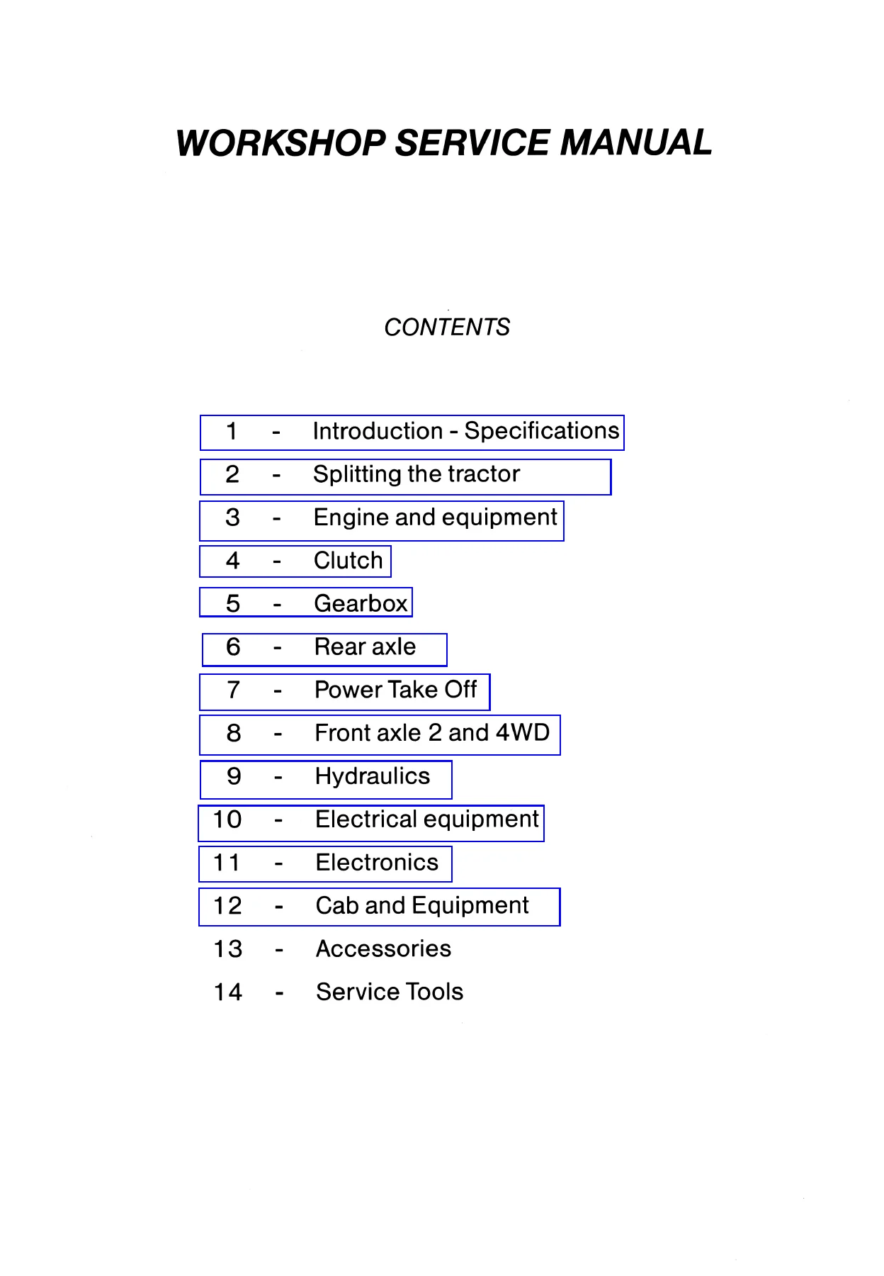
- 1 Introduction – Specifications: using the manual; specifications; chassis dimensions and mounting points; safety precautions; practical advice; installation instructions; conversion table; sealants; tightening torques
- 2 Splitting the tractor: engine to gearbox; gearbox to rear axle (cab integral with rear axle); front frame/support to engine
- 3 Engine and equipment: general engine data and viscostatic fan; engine flywheel; spacer for spring-loaded clutch; spacer for pressure-loaded clutch
- 4 Clutch: pressure-loaded oil-bath clutch; spring-loaded oil-bath clutch
- 5 Gearbox – standard and heavy-duty: transmission assembly / main gearbox; input unit; Speedshift; Dynashift; reverse shuttle; mechanical and electrohydraulic selector covers; selector rail and forks; output shaft; layshaft; mainshaft; creeper gears; super creeper gears
- 6 Rear axle: description; lift cover; trumpet housings; heavy-duty trumpets; handbrake; differential; brake pistons and seals
- 7 Power take-off: intermediate shaft, driving pinion and PTO brake; removable PTO shaft; shiftable PTO shaft; ground-speed PTO; PTO clutch
- 8 Front axle 2WD and 4WD: 4WD clutch assembly; final drive units; differential; 2WD front axle; steering column; bearings
- 9 Hydraulics – open centre and closed centre: circuit description; trailer braking; auxiliary spool valves; lift control valve; hydrostatic steering; low-pressure components; brake and clutch master-cylinder circuit; distribution valve/block; right- and left-hand hydraulic covers; clutch control valve; Dynashift control; hydraulic tests
- 10 Electrical equipment: electrical system, engine and equipment wiring, lighting wiring and fuse layout
- 11 Electronics: tester-programmer description and reprogramming; electronic lift control description, electrical system, auto-diagnostic and tester checks; Autotronic 2 description, checks with and without tester, parameters and reprogramming; Datatronic description and tester use
- 12 Cab and equipment: instrument panel; air conditioning; recharging the system with refrigerant; air-conditioning faults and compressor
IMAGES PREVIEW
Taken as a whole, the Massey Ferguson 6100 Series Tractors Workshop Service Manual – MF 6110 to 6190 is a chassis, transmission and systems workshop, not a stand-alone Perkins engine rebuild book. Identification marks in the text (circle for the part, square for an adjustment, triangle for a critical removal or refitment point) flag the steps that change a setting or that must not be missed when the tractor is opened. Special tool numbers are printed next to the operation that needs them, and torque figures in the procedures are required to be followed exactly.
Splitting the Tractor, Clutch and Gearbox Work
Section 2 is the entry point for almost every major repair in this 6100 Series workshop service manual. It shows how to uncouple and recouple the tractor between the engine and gearbox, between the gearbox and rear axle with the cab remaining on the axle, and between the front frame and the engine, including the service tools used to support the split. Those sequences are then called from later chapters whenever a clutch, input unit or front housing has to come off.
Clutch coverage separates the two oil-bath designs used on the range: a spring-loaded four-disc clutch on 6110-6160 and a pressure-loaded five-disc clutch on 6170-6190. Procedures cover oil-seal and O-ring renewal, clutch removal and shimming (play J1 of 0.6 to 0.8 mm is specified on the pressure-loaded assembly), bleeding the control or control valve, and pedal adjustment. A serial-number note records the LUK damper arrangement on 6170 and 6180 tractors from serial number F058049 and on 6190 tractors.
The gearbox section is the largest mechanical block in the Massey Ferguson 6100 Series Tractors Workshop Service Manual – MF 6110 to 6190. It treats both the standard and heavy-duty boxes and both Speedshift and Dynashift input units. Without Dynashift the transmission is described as 16 forward and 16 reverse speeds with a synchronised reverse shuttle; creeper ratio 4 to 1 and super creeper ratio 7.8 to 1 are listed as options. With Dynashift the book describes 32 speeds in each direction and four ratios selectable without declutching. Workshop tasks include removing the input unit, disassembling Dynashift planetary carriers and clutches, overhauling the reverse shuttle, setting mechanical and electrohydraulic selector covers, renewing selector rails and forks, and shimming layshaft, output shaft and mainshaft assemblies. Layshaft end-float J2 is given as 0.04 to 0.12 mm where that shimming step applies.
Rear Axle, PTO and Front Axle
Rear-axle work in this MF 6110 to 6190 workshop service manual covers the centre housing, lift cover, standard and heavy-duty trumpet housings with planetary reductions, handbrake acting on the rear-axle bevel gear, the positive-clutch differential lock, and oil-immersed brake pistons and seals with bleeding of the main and trailer-brake circuits. Epicyclic final-reduction ratios printed in the specification pages are 4.714 to 1 on 6110-6140 normal duty, 5.077 to 1 on 6150-6170 heavy duty and 5.571 to 1 on 6180-6190.
Independent PTO is hydraulic-clutch driven and proportional to engine speed, with 540 rev/min at 1980 engine rev/min and 1000 rev/min at 2000 engine rev/min. Speed change is either by interchangeable 35 mm shafts (6-spline 540 and 21-spline 1000) or by an external selector. Economy PTO, ground-speed PTO and optional front PTO (1000 rev/min at 2040 engine rev/min, ratio 2.04:1) each have their own removal, shimming and clutch procedures, including the PTO brake.
Front-axle chapters separate 4WD clutch, final drives, differential, the 2WD axle, the fixed or tiltable telescopic hydrostatic steering column, and frame bearings. 4WD engagement is hydraulic and electrically actuated from a cab push-button. Toe-in adjustment is called up after steering-arm, hub or axle work.
Open-Centre and Closed-Centre Hydraulics
Hydraulics occupy a dual path in the Massey Ferguson 6100 Series Tractors Workshop Service Manual – MF 6110 to 6190 because the range uses both open-centre and closed-centre layouts. The introduction describes a two-stage engine-driven gear pump: first stage 29 l/min at a maximum of 17 bar for steering, Hare/Tortoise range, differential locks, PTO clutch and brake, 4WD, master-cylinder top-up, clutch control valve, transmission lubrication and Speedshift or Dynashift; second stage 50 l/min at a maximum of 185 bar for trailer brake, auxiliaries and the hydraulic lift. Filtration is an external 150-micron suction strainer and a 15-micron high-pressure filter.
Workshop procedures then follow each circuit through trailer-brake valves, auxiliary spool valves and flow dividers, Bosch lift control valves with lift and lower solenoids, Orbitrol hydrostatic steering, 17-bar distribution components, right- and left-hand hydraulic covers, the clutch control valve (including its Dynashift section) and the pressure/flow tests run with the MF 3001 gauge kit and MF 3002 hose set. Test oil temperature is specified at a minimum of 60 degrees C (140 degrees F). Lift-force tables give horizontal and fully raised capacities for each ram size and lift-rod position so a technician can confirm the linkage geometry after cover or ram work.
Electrical System, Autotronic 2, Datatronic and Cab
Electrical equipment is built around the 12-volt negative-earth system already listed in the specifications, with harness breakdowns for engine and equipment wiring, lighting (European-code headlights 40/45 W, work lamps 55 W H3), instrument-panel and roof circuits, and a fuse box split between lighting and engine/equipment protection. Safety start is through the clutch pedal.
Section 11 is the diagnostic heart of later 6100 tractors. It describes the tester-programmer kit, how it is connected and updated, then walks through electronic lift control (control panel, position and draft sensors, auto-diagnostic and tester-based sensor adjustment). Autotronic 2 coverage includes hydro-electrical reverse-shuttle diagrams, fault-finding with and without the tester, parameter screens keyed to tractor model, and on-tractor or off-tractor reprogramming. Datatronic pages explain the performance-monitor screen, symbols, memory modes and tester connection. These chapters are what a technician needs when a shuttle, lift or transmission controller will not accept a ratio or reports a sensor fault.
Cab work covers the instrument-panel warning-light identification, the air-conditioning circuit using R134a, discharge and recharge with a dedicated evacuating/charging station, pressure checks, and compressor diagnosis. The book is explicit that the circuit must not be opened without the correct R134a equipment and that refrigerant must not be vented near a flame.
Download the Massey Ferguson 6100 Series Tractors Workshop Service Manual – MF 6110 to 6190
With this Massey Ferguson 6100 Series Tractors Workshop Service Manual – MF 6110 to 6190 on the bench you can split the tractor at the documented joints, overhaul the wet clutch and input unit, rebuild Speedshift or Dynashift gearboxes and the reverse shuttle, service rear trumpets, differential lock and oil-immersed brakes, renew PTO shafts and clutches, work 2WD and 4WD front axles, test open- or closed-centre hydraulics, trace electrical harnesses, and diagnose electronic lift, Autotronic 2 and Datatronic faults using the tester procedures printed in the book. Correct shimming values, pump pressures, PTO engine speeds and tightening torques are the difference between a transmission that lasts and one that fails after a hurried rebuild.
After payment the file is delivered instantly as a PDF. There is no shipping wait. Open it on a workshop computer, tablet or phone and print the pages you need for the job in front of you.
Reviews
There are no reviews yet.