
★ TRUSTED BY 321,897+ PROFESSIONALS WORLDWIDE
🏢
Trusted Business
Verified & Licensed
🛡️
Virus Free Files
100% Safe Downloads
🔒
Secure Payment
SSL Protected
Instant Delivery
Available Immediately
Sale!

CMC Electronics CMA-9000 Flight Management System Installation & Flight Line Manual (2007)

Original price was: $44.95.Current price is: $24.95.

Complete 2007 CMC Electronics CMA-9000 Flight Management System Installation and Flight Line Manual covering installation, post-installation testing, troubleshooting, and configuration for hardware variation 100-601951-VAR.

Instant PDF Download
Available immediately
💾
Save to Your Device
Download & keep forever
🛡️
Antivirus Scanned
100% virus-free
🌍
Trusted Worldwide
175,000+ customers

Description

CMC Electronics CMA-9000 Flight Management System Installation & Flight Line Manual

This is the complete original CMA-9000 Installation/Flight Line Manual published by CMC Electronics Inc. for the CMA-9000 Flight Management System, hardware variation 100-601951-VAR with software 169-614876-010. If you install, configure, or maintain a CMA-9000 FMS on the flight line, this CMA-9000 Flight Management System manual is the factory reference for the job.

File Details

  • Manual type: Installation/Flight Line Manual
  • Brand / Model: CMC Electronics CMA-9000 Flight Management System
  • Hardware: 100-601951-VAR, Software: 169-614876-010
  • Publication No. 9000-GEN-0840, Item No. 929-600026-000
  • Reference 34-61-14, dated May 10, 2007 (Original, Revision 0)
  • Language: English
  • Page count: 395 pages
  • File format: PDF, instant digital download

Chapters Covered

  • Section I – Description and Operation: purpose, function, reliability/MTBF, external interface capabilities, primary navigation modes, annunciators and keys, related publications, equipment identification
  • Equipment Specifications: applicable ARINC/FAA/RTCA/SAE/JAA/military documents
  • Digital Equipment interfaces: ACMS, Air Data Computer (ARINC 429/575), AHRS, AFCS, DME receivers, EFIS interfaces (GAMA, IFDS/AHCAS, ARINC 702), Fuel Computer, GPS Sensor, Flight Recorder, VOR/ILS receiver, VOR receiver, X-FMS cross-talk, ELT, ATC transponders, VHF Comm, ADF, Audio Management Unit, APIRS, Digital Map System, Data Concentrator, Radio Altimeter, LN-100GT and SIGMA50H embedded GPS/INS, Weather Radar, Doppler Velocity Sensor, Personnel Locator System, TACAN, Data Loader units, Inertial Reference System
  • Section II – Installation: equipment location, GPS receiver/antenna selection, active antenna installations, interwiring and outline drawing, harness voltage checkout, EGI installation, Doppler installation, annunciator installation
  • Section III – Post-Installation Test: Built-In Test, front panel brightness, configuration selection, navigation database loading, power on, annunciator test, heading verification, true airspeed verification, GPS sensor unit, DME status, VOR/DME/TCN status, radio test, discrete output test, EFIS interface test, EMC test, IRS-to-FMS-to-IRS ground check
  • Section IV – Flight Line Test/Troubleshooting: alert messages, troubleshooting philosophy, fault log with system alert, maintenance alert, maintenance advisory, and status advisory messages
  • Section V – Maintenance Practices, Section VI – Servicing, Section VII – Removal/Installation procedures
  • Section VIII – Cleaning/Painting, Section IX – Approved Repairs
  • Section X – Configuration Selection: four configuration capabilities, configuration diskette and manual configuration procedures
  • Section XI – Data Loader Unit (DLU): ARINC 615 DLU and RS-422 DLU database/configuration loading and saving
  • Appendix A: Ground Functional Test Procedures; Appendix B: Flight Functional Test Procedures & Report; Appendix C: Procedures for Obtaining Civil Authorities Approval for follow-on FMS/GPS installations

IMAGES PREVIEW

CMC Electronics CMA-9000 Flight Management System Installation & Flight Line Manual (2007) — PDF page 1 preview
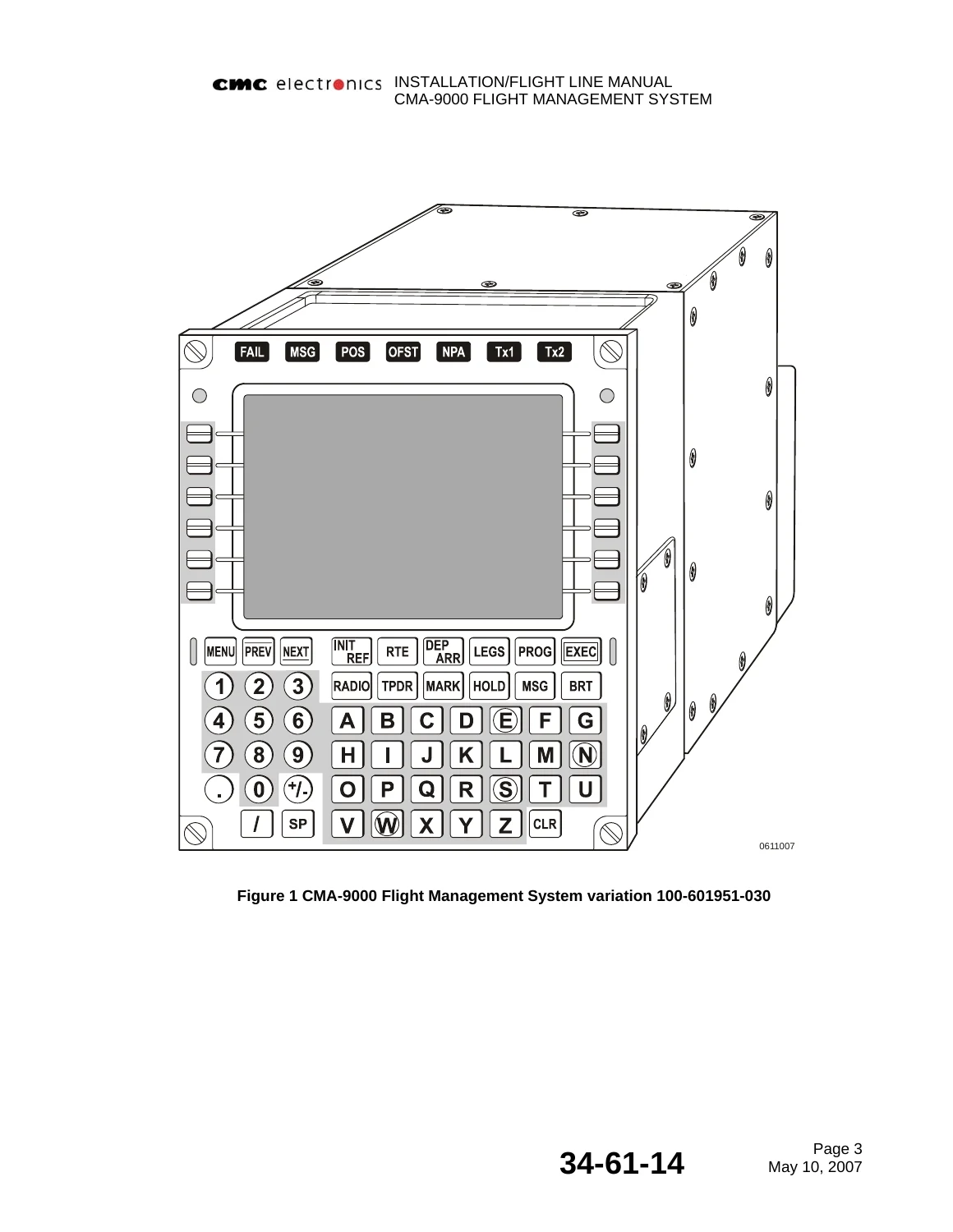
CMC Electronics CMA-9000 Flight Management System Installation & Flight Line Manual (2007) — PDF page 32 preview
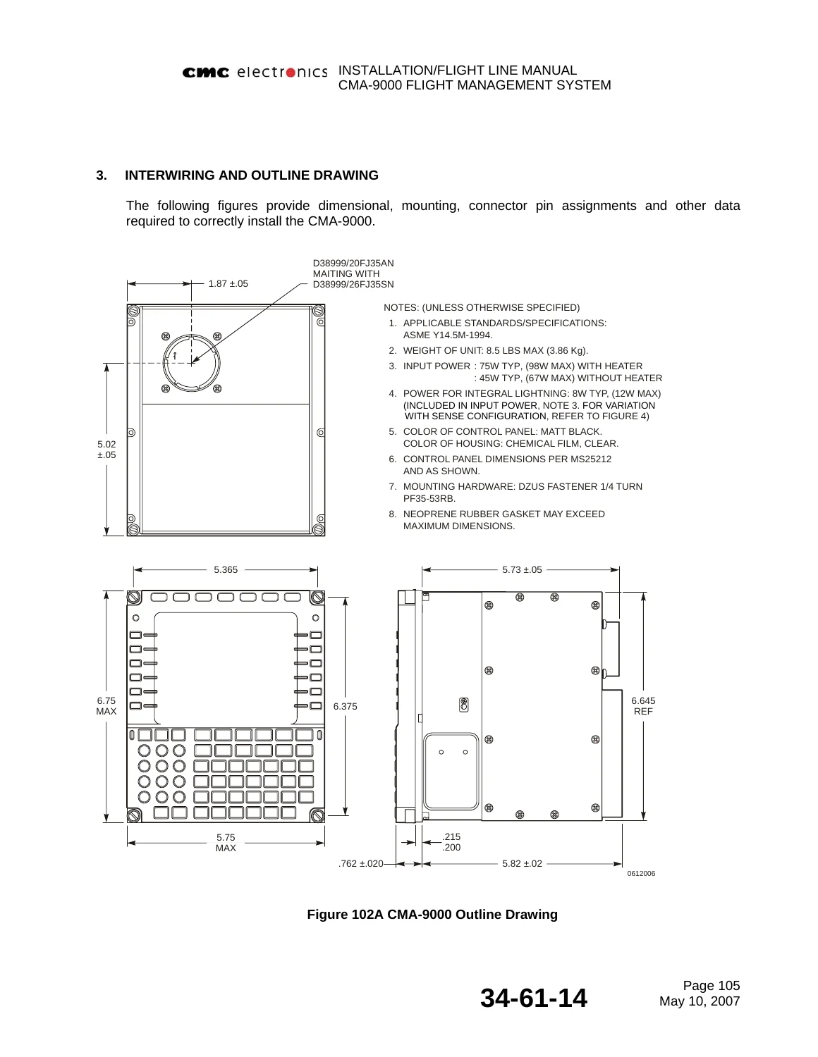
CMC Electronics CMA-9000 Flight Management System Installation & Flight Line Manual (2007) — PDF page 130 preview

Taken together, this CMA-9000 Flight Management System manual walks a technician from initial equipment location and wiring through post-installation testing, flight line fault diagnosis, and full configuration selection, with dedicated appendices for ground and flight functional test sign-off.

Physical, Power & Environmental Specifications

The manual documents the CMA-9000 unit as 147.57 mm (5.81 in) deep, 146.05 mm (5.75 in) wide, and 171.45 mm (6.75 in) high, weighing 3.86 kg (8.5 lb) maximum. Power dissipation is specified at +28 Vdc, 45.0W typical at ambient rising to 75.0W during cold-temperature startup, with integral lighting drawing up to 12.0W at 5.0 Vdc. Environmental qualification is documented to RTCA DO-160E, including temperature (Category A4B4), altitude, decompression, vibration, humidity, shock, EMI, lightning, and electrostatic discharge categories – all reproduced from the original CMC Electronics documentation.

Complete PDF Bookmark Tree

Complete Bookmarks

The complete bookmarks in the “CMC Electronics CMA-9000 Flight Management System Installation & Flight Line Manual (2007)” are as follows:

CMA-9000 INSTALLATION/FLIGHT LINE MANUAL FMSp. 1
CMA-9000 INSTALLATION/FLIGHT LINE MANUAL FMSp. 2
WE VALUE YOUR COMMENTSp. 4
CUSTOMER COMMENTSp. 6
MAILING ADDRESSp. 7
LIST OF EFFECTIVE PAGESp. 8
LIST OF EFFECTIVE PAGES LEP-2p. 9
LIST OF EFFECTIVE PAGES LEP-3p. 10
LIST OF EFFECTIVE PAGES LEP-4p. 11
LIST OF EFFECTIVE PAGES LEP-5p. 12
RECORD OF REVISIONSp. 14
SERVICE BULLETIN LISTp. 16
FORWARD ELECTROSTATIC DISCHARGEp. 18
WARRANTYp. 18
LIST OF STANDARD AND NONSTANDARD ABBREVIATIONSp. 20
LIST OF STANDARD AND NONSTANDARD ABBREVIATIONS (cont’d)p. 21
LIST OF STANDARD AND NONSTANDARD ABBREVIATIONS (cont’d)p. 22
TABLE OF CONTENTSp. 24
TABLE OF CONTENTS (cont'd)p. 25
TABLE OF CONTENTS (cont'd)p. 26
TABLE OF CONTENTS (cont'd)p. 27
LIST OF FIGURESp. 28
LIST OF TABLESp. 29
SECTION I DESCRIPTION AND OPERATIONp. 30
1. GENERALp. 30
A. Purpose of Manualp. 30
B. Function of Equipmentp. 30
C. Reliability and Maintainabilityp. 30
D. External Interface Capabilitiesp. 31
Figure 1 CMA-9000 Flight Management System variation 100-601951-030p. 32
E. Description of the Primary Modes of Navigationp. 33
F. Annunciators and Keysp. 36
Figure 2A Annunciators and Keys of CMA-9000 variation 100-601951-030p. 37
Figure 2B Annunciators and Keys of CMA-9000 variation 100-601951-VAR 001/101/301p. 38
Figure 2C Annunciators and Keys of CMA-9000 variation 100-601951-VARp. 39
Figure 2D Annunciators and Keys of CMA-9000 variation 100-601951-VAR 040p. 40
Figure 2E Annunciators and Keys of CMA-9000 variation 100-601951-VAR 050p. 41
Figure 2F Annunciators and Keys (Sheet 1 of 5)p. 42
Figure 2F Annunciators and Keys (Sheet 2 of 5)p. 43
Figure 2F Annunciators and Keys (Sheet 3 of 5)p. 44
Figure 2F Annunciators and Keys (Sheet 4 of 5)p. 45
Figure 2F Annunciators and Keys (Sheet 5 of 5)p. 46
G. Related Publicationsp. 47
Figure 3 Related Publicationsp. 47
H. Equipment Identificationp. 48
Figure 4 Equipment Identification (Sheet 1 of 2)p. 48
Figure 4 Equipment Identification (Sheet 2 of 2)p. 49
2. EQUIPMENT SPECIFICATIONSp. 50
Figure 5 Equipment Specification (Sheet 1 of 3)p. 50
Figure 5 Equipment Specification (Sheet 2 of 3)p. 51
Figure 5 Equipment Specification (Sheet 3 of 3)p. 52
Figure 6 Physical Specificationp. 53
Figure 7 Environmental Specification (Sheet 1 of 2)p. 54
Figure 7 Environmental Specification (Sheet 2 of 2)p. 55
Figure 8A Single Basic System with Radio Tuningp. 56
Figure 8B Single Basic System without Radio Tuningp. 57
Figure 8C Dual Systemp. 58
Figure 8D System Block Diagram Dual Systemp. 59
Figure 8E Dual FMS installation with radio tuning and suggested pins allocation (courtesy ofp. 60
Figure 9 FMS Viewing Envelopep. 61
3. DIGITAL EQUIPMENTp. 62
Table 1 ARINC 429 Equipment Supported by the CMA-9000p. 62
A. Aircraft Condition Monitoring System (ACMS)p. 63
B. Air Data Computer (ARINC 429)p. 64
C. Air Data Computer (ARINC 575)p. 65
D. Attitude and Heading Reference System (ARINC 429)p. 65
E. Automatic Flight Control Systemp. 66
F. Checker (ARINC 429)p. 67
G. Collins DME-442/DME-4000 Distance Measuring Equipment Receiver (ARINC 429)p. 67
H. Collins 700 Distance Measuring Equipment Receiver (ARINC 429)p. 68
I. Chelton DM-441B Distance Measuring Equipment Receiver (ARINCp. 69
J. ARINC 615 Data Loader Unit (ARINC 429)p. 69
K. GAMA EFIS Interface Descriptionp. 69
L. IFDS and AHCAS/AHCAS2 EFIS Interface Descriptionp. 79
M. ARINC 702 EFIS Interface Descriptionp. 83
N. Fuel Computerp. 91
O. GPS Sensorp. 91
P. Flight Recorderp. 96
Q. Repeaterp. 96
R. System Management Computerp. 97
S. Chelton VN-411B, Collins VIR-432, Collins NAV-4500 NAV (VOR/ILS) RECEIVER (ARINC 429)p. 97
T. VOR RECEIVER (ARINC 579)p. 98
U. X-FMS for cross-talk (ARINC 429)p. 98
V. Emergency Locator Transmitter ARTEX ELT-110-406HM/GPS (ARINC 429)p. 99
W. Bendix King MST67A ATC Transponder (ARINC 429)p. 99
X. Collins TDR 94D ATC Transponder (ARINC 429)p. 100
Y. Chelton VC-401B VHF COM radio (ARINC 429)p. 101
Z. Chelton VC-401C VHF Comm (ARINC 429)p. 101
AA. Chelton ADF-431B, Collins ADF-462 ADF (ARINC 429)p. 102
BB. Marconi Selenia SRT-651/N-A V/UHF radio (ARINC 429)p. 102
CC. TEAM Audio Management Unit AMU (ARINC 429)p. 103
DD. Aircraft Piloting Inertial Reference System (APIRS SFIM)p. 104
EE. Digital Map Systemp. 104
FF. Data Concentratorp. 106
GG. Radio Altimeter (ARINC 429)p. 107
HH. LN-100GT Embedded GPS/INS Sensor (ARINC 429)p. 107
II. SIGMA50H Embedded GPS/INS Sensor (ARINC 429)p. 109
JJ. Weather Radar (ARINC 429)p. 111
KK. Doppler Velocity Sensor DVS (ARINC 429)p. 111
LL. Personnel Locator System (ARINC 429)p. 112
MM. Thomson NC-12B TACAN (ARINC 429)p. 113
NN. Data Loader unit Targa (RS-422)p. 113
OO. Helicopter Communication System (HCS) Software Protocol (RS-422)p. 114
PP. Radio Interface Box (RIB) equipment (RS-422) Future Growthp. 117
QQ. Inertial Reference System (ARINC 429)p. 118
Figure 10 Triple FMS/Triple-LTN-92 IRS Interconnectionsp. 122
Figure 11 FMU to LTN-92 INU Source Select (All Relays Shown Energized)p. 123
Figure 12 Heading Sources for Triple FMS/Triple LTN-92 IRS/Dual Compass Couplersp. 124
SECTION II INSTALLATIONp. 126
1. GENERALp. 126
2. EQUIPMENT LOCATIONp. 126
A. Generalp. 126
B. Location of the FMSp. 126
C. Selection and location of the GPS receiver and related GPS Antennap. 126
D. Active Antenna Installations (CMA-3012 and CMA-3024)p. 128
Figure 101A Typical CMA-9000 Location (for a helicopter)p. 129
Figure 101B Typical CMA-9000 Location (for an aircraft)p. 129
3. INTERWIRING AND OUTLINE DRAWINGp. 130
Figure 102A CMA-9000 Outline Drawingp. 130
Figure 102B CMA-9000 J1 Connectorp. 131
Figure 103 FMS Pin Assignments (Sheet 1 of 5)p. 132
Figure 103 FMS Pin Assignments (Sheet 2 of 5)p. 133
Figure 103 FMS Pin Assignments (Sheet 3 of 5)p. 134
Figure 103 FMS Pin Assignments (Sheet 4 of 5)p. 135
Figure 103 FMS Pin Assignments (Sheet 5 of 5)p. 136
Figure 104 Interwiring Specifications (Sheet 1 of 5)p. 137
Figure 104 Interwiring Specifications (Sheet 2 of 5)p. 138
Figure 104 Interwiring Specifications (Sheet 3 of 5)p. 139
Figure 104 Interwiring Specifications (Sheet 4 of 5)p. 140
Figure 104 Interwiring Specifications (Sheet 5 of 5)p. 141
4. HARNESS VOLTAGE CHECKOUTp. 142
Figure 105 Input Wiring Checks for CMA-9000 hardware variation 100-601951-XXXp. 142
5. EGI INSTALLATIONp. 142
6. DOPPLER INSTALLATIONp. 143
7. ANNUNCIATOR INSTALLATIONp. 144
SECTION III POST-INSTALLATION TESTp. 146
1. GENERALp. 146
2. CONDITIONSp. 146
3. SYSTEM TEST PREPARATIONp. 146
A. Built-In Testp. 146
B. Front panel brightness controlp. 148
Figure 201 Integral Lighting 5V Curvep. 149
C. Configuration Selectionp. 149
D. Navigation Database Loadingp. 149
4. PROCEDUREp. 150
A. Power Onp. 150
B. Annunciator Test and RADIO Pagep. 150
C. Heading Input Verificationp. 153
D. True Airspeed Verificationp. 154
E. GPS Sensor Unitp. 155
F. DME Statusp. 160
G. VOR/DME/TCN Statusp. 161
H. Radio Testp. 162
I. Discrete Output Testp. 162
J. EFIS Interface Testp. 163
Figure 202. Typical Map Mode Displayp. 165
Figure 203. Typical ARC Mode Displayp. 165
K. Electromagnetic Compatibility Testp. 166
Figure 204 EMC Matrix Chartp. 169
L. IRS to FMS to IRS Ground Checkp. 170
SECTION IV FLIGHT LINE TEST/TROUBLESHOOTINGp. 172
1. GENERALp. 172
2. ALERT MESSAGESp. 172
3. TROUBLESHOOTING PHILOSOPHYp. 172
4. FAULT LOGp. 173
A. SYSTEM ALERT MESSAGESp. 173
Figure 301 System Alert Messages (Sheet 1 of 10)p. 173
Figure 301 Messages (Sheet 2 of 10)p. 174
Figure 301 Messages (Sheet 3 of 10)p. 175
Figure 301 Messages (Sheet 4 of 10)p. 176
Figure 301 Messages (Sheet 5 of 10)p. 177
Figure 301 Messages (Sheet 6 of 10)p. 178
Figure 301 Messages (Sheet 7 of 10)p. 179
Figure 301 Messages (Sheet 8 of 10)p. 180
Figure 301 Messages (Sheet 9 of 10)p. 181
Figure 301 Messages (Sheet 10 of 10)p. 182
B. MAINTENANCE ALERT MESSAGESp. 183
Figure 302 Maintenance Alert Messages (Sheet 1 of 2)p. 183
Figure 302 Maintenance Alert Messages (Sheet 2 of 2)p. 184
C. MAINTENANCE ADVISORY MESSAGESp. 185
Figure 303 Maintenance Advisory Messages (Sheet 1 of 7)p. 185
Figure 303 Maintenance Advisory Messages (Sheet 2 of 7)p. 186
Figure 303 Maintenance Advisory Messages (Sheet 3 of 7)p. 187
Figure 303 Maintenance Advisory Messages (Sheet 4 of 7)p. 188
Figure 303 Maintenance Advisory Messages (Sheet 5 of 7)p. 189
Figure 303 Maintenance Advisory Messages (Sheet 6 of 7)p. 190
Figure 303 Maintenance Advisory Messages (Sheet 7 of 7)p. 191
D. STATUS ADVISORY MESSAGESp. 192
Figure 304 Status Advisory Messages (Sheet 1 of 5)p. 192
Figure 304 Status Advisory Messages (Sheet 2 of 5)p. 193
Figure 304 Status Advisory Messages (Sheet 3 of 5)p. 194
Figure 304 Status Advisory Messages (Sheet 4 of 5)p. 195
Figure 304 Status Advisory Messages (Sheet 5 of 5)p. 196
SYSTEM TEST PROCEDURE FOR FMSp. 197
Figure 305 Testing/Troubleshooting Flow Chart (Sheet 1 of 7)p. 197
Figure 305 Testing/Troubleshooting Flow Chart (Sheet 2 of 7)p. 198
Figure 305 Testing/Troubleshooting Flow Chart (Sheet 3 of 7)p. 199
Figure 305 Testing/Troubleshooting Flow Chart (Sheet 4 of 7)p. 200
Figure 305 Testing/Troubleshooting Flow Chart (Sheet 5 of 7)p. 201
Figure 305 Testing/Troubleshooting Flow Chart (Sheet 6 of 7)p. 202
Figure 305 Testing/Troubleshooting Flow Chart (Sheet 7 of 7)p. 203
CMA-9000 MAINTENANCE PAGESp. 204
Figure 306 Maintenance Pages (Sheet 1 of 7)p. 204
Figure 306 Maintenance Pages (Sheet 2 of 7)p. 205
Figure 306 Maintenance Pages (Sheet 3 of 7)p. 206
Figure 306 Maintenance Pages (Sheet 4 of 7)p. 207
Figure 306 Maintenance Pages (Sheet 5 of 7)p. 208
Figure 306 Maintenance Pages (Sheet 6 of 7)p. 209
Figure 306 Maintenance Pages (Sheet 7 of 7)p. 210
Figure 307 Maintenance Test 1p. 211
Figure 308 Maintenance Test 2p. 211
Figure 309 Typical Full Rose Map Display (Sheet 1 of 2)p. 212
Figure 309 Typical ARC Map Mode Display (Sheet 2 of 2)p. 213
Figure 310 Typical ARC NAV Displayp. 213
Figure 311 Typical Plan Modep. 214
Figure 312 Label 271 Maintenance Action FMS Statusp. 215
SECTION V MAINTENANCE PRACTICESp. 217
1. GENERALp. 217
SECTION VI SERVICINGp. 219
1. GENERALp. 219
SECTION VII REMOVAL/INSTALLATIONp. 221
1. GENERALp. 221
2. REMOVAL PROCEDURESp. 221
A. Generalp. 221
B. Flight Management System (FMS)p. 221
3. PRE-INSTALLATION INSPECTIONp. 221
4. INSTALLATION OF UNITSp. 221
5. POST-INSTALLATION INSPECTIONp. 222
6. POST-INSTALLATION TESTSp. 222
SECTION VIII CLEANING/PAINTINGp. 223
1. GENERALp. 223
A. Cleaning and Painting of Surfacesp. 223
B. Display Glass Cleaningp. 223
SECTION IX APPROVED REPAIRSp. 225
1. GENERALp. 225
SECTION X CONFIGURATION SELECTIONp. 227
1. GENERALp. 227
2. CONFIGURATION CAPABILITIES OF THE CMA-9000: FOUR CONFIGURATIONSp. 227
3. FMS Configuration Selection Procedurep. 227
A. FMS Configuration Procedure Using Configuration Diskettep. 229
B. Manual FMS Configuration Procedurep. 230
FMS CONFIGURATION PAGEp. 235
Figure 901 FMS Configuration Pages (Sheet 1 of 60)p. 235
Figure 901 FMS Configuration Pages (Sheet 2 of 60)p. 236
Figure 901 FMS Configuration Pages (Sheet 3 of 60)p. 237
Figure 901 FMS Configuration Pages (Sheet 4 of 60)p. 238
Figure 901 FMS Configuration Pages (Sheet 5 of 60)p. 239
Figure 901 FMS Configuration Pages (Sheet 6 of 60)p. 240
Figure 901 FMS Configuration Pages (Sheet 7 of 60)p. 241
Figure 901 FMS Configuration Pages (Sheet 8 of 60)p. 242
Figure 901 FMS Configuration Pages (Sheet 9 of 60)p. 243
Figure 901 FMS Configuration Pages (Sheet 10 of 60)p. 244
Figure 901 FMS Configuration Pages (Sheet 11 of 60)p. 245
Figure 901 FMS Configuration Pages (Sheet 12 of 60)p. 246
Figure 901 FMS Configuration Pages (Sheet 13 of 60)p. 247
Figure 901 FMS Configuration Pages (Sheet 14 of 60)p. 248
Figure 901 FMS Configuration Pages (Sheet 15 of 60)p. 249
Figure 901 FMS Configuration Pages (Sheet 16 of 60)p. 250
Figure 901 FMS Configuration Pages (Sheet 17 of 60)p. 251
Figure 901 FMS Configuration Pages (Sheet 18 of 60)p. 252
Figure 901 FMS Configuration Pages (Sheet 19 of 60)p. 253
Figure 901 FMS Configuration Pages (Sheet 20 of 60)p. 254
Figure 901 FMS Configuration Pages (Sheet 21 of 60)p. 255
Figure 901 FMS Configuration Pages (Sheet 22 of 60)p. 256
Figure 901 FMS Configuration Pages (Sheet 23 of 60)p. 257
Figure 901 FMS Configuration Pages (Sheet 24 of 60)p. 258
Figure 901 FMS Configuration Pages (Sheet 25 of 60)p. 259
Figure 901 FMS Configuration Pages (Sheet 26 of 60)p. 260
Figure 901 FMS Configuration Pages (Sheet 27 of 60)p. 261
Figure 901 FMS Configuration Pages (Sheet 28 of 60)p. 262
Figure 901 FMS Configuration Pages (Sheet 29 of 60)p. 263
Figure 901 FMS Configuration Pages (Sheet 30 of 60)p. 264
Figure 901 FMS Configuration Pages (Sheet 31 of 60)p. 265
Figure 901 FMS Configuration Pages (Sheet 32 of 60)p. 266
Figure 901 FMS Configuration Pages (Sheet 33 of 60)p. 267
Figure 901 FMS Configuration Pages (Sheet 34 of 60)p. 268
Figure 901 FMS Configuration Pages (Sheet 35 of 60)p. 269
Figure 901 FMS Configuration Pages (Sheet 36 of 60)p. 270
Figure 901 FMS Configuration Pages (Sheet 37 of 60)p. 271
Figure 901 FMS Configuration Pages (Sheet 38 of 60)p. 272
Figure 901 FMS Configuration Pages (Sheet 39 of 60)p. 273
Figure 901 FMS Configuration Pages (Sheet 40 of 60)p. 274
Figure 901 FMS Configuration Pages (Sheet 41 of 60)p. 275
Figure 901 FMS Configuration Pages (Sheet 42 of 60)p. 276
Figure 901 FMS Configuration Pages (Sheet 43 of 60)p. 277
Figure 901 FMS Configuration Pages (Sheet 44 of 60)p. 278
Figure 901 FMS Configuration Pages (Sheet 45 of 60)p. 279
Figure 901 FMS Configuration Pages (Sheet 46 of 60)p. 280
Figure 901 FMS Configuration Pages (Sheet 47 of 60)p. 281
Figure 901 FMS Configuration Pages (Sheet 48 of 60)p. 282
Figure 901 FMS Configuration Pages (Sheet 49 of 60)p. 283
Figure 901 FMS Configuration Pages (Sheet 50 of 60)p. 284
Figure 901 FMS Configuration Pages (Sheet 51 of 60)p. 285
Figure 901 FMS Configuration Pages (Sheet 52 of 60)p. 286
Figure 901 FMS Configuration Pages (Sheet 53 of 60)p. 287
Figure 901 FMS Configuration Pages (Sheet 54 of 60)p. 288
Figure 901 FMS Configuration Pages (Sheet 55 of 60)p. 289
Figure 901 FMS Configuration Pages (Sheet 56 of 60)p. 290
Figure 901 FMS Configuration Pages (Sheet 57 of 60)p. 291
Figure 901 FMS Configuration Pages (Sheet 58 of 60)p. 292
Figure 901 FMS Configuration Pages (Sheet 59 of 60)p. 293
Figure 901 FMS Configuration Pages (Sheet 60 of 60)p. 294
CONFIGURATION CHARTp. 295
Figure 902 Configuration Selections (Sheet 1 of 18)p. 295
Figure 902 Configuration Selections (Sheet 2 of 18)p. 296
Figure 902 Configuration Selections (Sheet 3 of 18)p. 297
Figure 902 Configuration Selections (Sheet 4 of 18)p. 298
Figure 902 Configuration Selections (Sheet 5 of 18)p. 299
Figure 902 Configuration Selections (Sheet 6 of 18)p. 300
Figure 902 Configuration Selections (Sheet 7 of 18)p. 301
Figure 902 Configuration Selections (Sheet 8 of 18)p. 302
Figure 902 Configuration Selections (Sheet 9 of 18)p. 303
Figure 902 Configuration Selections (Sheet 10 of 18)p. 304
Figure 902 Configuration Selections (Sheet 11 of 18)p. 305
Figure 902 Configuration Selections (Sheet 12 of 18)p. 306
Figure 902 Configuration Selections (Sheet 13 of 18)p. 307
Figure 902 Configuration Selections (Sheet 14 of 18)p. 308
Figure 902 Configuration Selections (Sheet 15 of 18)p. 309
Figure 902 Configuration Selections (Sheet 16 of 18)p. 310
Figure 902 Configuration Selections (Sheet 17 of 18)p. 311
Figure 902 Configuration Selections (Sheet 18 of 18)p. 312
SECTION XI DATA LOADER UNIT (DLU)p. 313
1. GENERALp. 313
2. DATA LOADER DESCRIPTIONp. 313
A. ARINC 615 Data Loader Unit (DLU)p. 313
B. Loading a database or FMS configuration with an ARINC 615 DLUp. 315
3. RS422 DLUp. 316
A. Loading a database or FMS configuration with the RS 422 DLUp. 316
B. Saving the User database or the FMS configuration into the RS422 DLUp. 318
APPENDIX Ap. 321
SECTION I GROUND FUNCTIONAL TEST PROCEDURESp. 321
TABLE OF CONTENTSp. 323
LIST OF FIGURESp. 324
1.0 PURPOSEp. 325
2.0 SCOPEp. 325
3.0 POST INSTALLATION VISUAL INSPECTIONp. 325
4.0 AIRCRAFT LOCATION AND POWER REQUIREMENTSp. 325
5.0 FMS GROUND TEST PROCEDUREp. 326
CROSS-TALK VERIFICATION (if multiple FMS are installed and cp. 328
7.0 EFIS VERIFICATION (if configured)p. 328
8.0 SET UP VERIFICATIONp. 328
9.0 HEADING INPUT VERIFICATION TESTp. 329
10.0 TRUE AIRSPEED VERIFICATION TESTp. 330
11.0 GPS SENSOR TESTp. 330
12.0 DME NAVIGATION VALIDITY TESTp. 333
13.0 VOR/DME OR VOR/DME/TCN NAVIGATION VALIDITY TESTp. 334
14.0 RADIO NAVIGATION TUNING TESTp. 335
15.0 ADF RECEIVER TUNING TESTp. 336
16.0 TRANSPONDER TUNING TESTp. 337
17.0 RADIO COMMUNICATION TUNING TESTp. 338
18.0 ANNUNCIATORS TESTp. 339
Figure A-1.1 Typical Map Mode Displayp. 341
Figure A-1.2 Typical ARC Mode Displayp. 341
19.0 ELECTROMAGNETIC COMPATIBILITY (EMC) GROUND TEST PLANp. 342
SECTION II GROUND FUNCTIONAL TEST REPORTp. 343
3.0 POST INSTALLATION VISUAL INSPECTIONp. 344
4.0 AIRCRAFT LOCATION AND POWER REQUIREMENTSp. 344
5.0 FMS GROUND TEST PROCEDUREp. 344
6.0 CROSS-TALK VERIFICATIONp. 344
7.0 EFIS VERIFICATIONp. 344
8.0 SETUP VERIFICATIONp. 344
9.0 HEADING INPUT VERIFICATION TESTp. 345
10.0 TRUE AIRSPEED VERIFICATION TESTp. 345
11.0 GPS TESTp. 345
12.0 DME NAVIGATION VALIDITY TESTp. 346
13.0 VOR/DME NAVIGATION VALIDITY TESTp. 346
14.0 RADIO NAVIGATION TUNING TESTp. 347
15.0 ADF RECEIVER TUNING TESTp. 347
16.0 TRANSPONDER TUNING TESTp. 347
17.0 RADIO COMMUNICATION TUNING TESTp. 347
18.0 ANNUNCIATORS TESTp. 348
APPENDIX Bp. 349
FLIGHT FUNCTIONAL TEST PROCEDURES & REPORTp. 349
TABLE OF CONTENTSp. 351
LIST OF FIGURESp. 351
FLIGHT FUNCTIONAL TEST PROCEDUREp. 353
1.0 PURPOSEp. 353
2.0 FLIGHT TEST PREREQUISITESp. 353
3.0 GENERALp. 353
FLIGHT FUNCTIONAL TEST PROCEDURE & REPORTp. 354
4.0 POWER ON and INITIALIZATION of FMSp. 354
5.0 BEARING & DISTANCE VERIFICATION OF WAYPOINTSp. 354
6.0 STATUS and MESSAGESp. 354
7.0 ENGINE START and GENERATOR LOAD SHARING TESTp. 355
8.0 GPS RECEPTION TESTp. 355
9.0 FMS OPERATION DURING TAKE-OFF and CLIMB-OUTp. 355
10.0 ENROUTE FMS INTERFACING CHECKSp. 355
11.0 NAVIGATION MODE – SENSOR TESTp. 356
12.0 DME/DME MODE OF NAVIGATIONp. 356
13.0 VOR/DME MODE of NAVIGATIONp. 357
14.0 GPS MODE of NAVIGATIONp. 357
15.0 DIRECT TO/INTERCEPT TESTp. 358
16.0 HOLDING PATTERN TESTp. 358
17.0 ENROUTE TO TERMINAL AND INSTRUMENT APPROACH PHASEp. 359
Figure B-1 Arrival Zonep. 364
ENROUTE TO TERMINAL AND INSTRUMENT APPROACH PHASE (cont'd)p. 365
HSI Sensitivity Tablep. 368
18.0 ELECTROMAGNETIC COMPATIBILITY (EMC) FLIGHT TEST PLANp. 369
19.0 PERFORM ANY OTHER TESTS THAT ARE NECESSARYp. 370
Figure B-2 EMC Matrix Chartp. 371
WAYPOINT ENTRY SHEETp. 372
FLIGHT FUNCTIONAL TEST PROCEDURE & REPORTp. 373
APPENDIX Cp. 375
PROCEDURES FOR OBTAINING CIVIL AUTHORITIES APPROVAL – IFR/VFR OPERATIONS FOR FOLLOW-ON FMS/GPS EQUIPMENT INSTALLATIONSp. 375
TABLE OF CONTENTSp. 377
LIST OF FIGURESp. 377
1. FOLLOW-ON MULTI-SENSOR EQUIPMENT INSTALLATIONS LIMITED TOp. 379
A. General Installation Methodsp. 379
B. Installation Criteriap. 379
C. Aircraft Flight Manual Supplement/Placard(s)p. 379
D. Functional Flight Evaluationp. 381
2. FOLLOW-ON MULTI-SENSOR EQUIPMENT INSTALLATIONS FOR IFR USEp. 381
A. Data Submitted by the Applicantp. 381
B. Additional Data That May be Requiredp. 381
C. Additional Data That May be Requiredp. 381
D. Functional Flight Evaluationp. 383
3. SAMPLE AIRPLANE FLIGHT MANUAL SUPPLEMENT (FAA Form 337 Approp. 383
Figure C-1 Sample Airplane Flight Manual Supplement (Sheet 1p. 384
Figure C-1 Sample Airplane Flight Manual Supplement (Sheet 2p. 385
Figure C-1 Sample Airplane Flight Manual Supplement (Sheet 3p. 386
Figure C-1 Sample Airplane Flight Manual Supplement (Sheet 4p. 387
Figure C-1 Sample Airplane Flight Manual Supplement (Sheet 5p. 388
Figure C-1 Sample Airplane Flight Manual Supplement (Sheet 6p. 389
Figure C-1 Sample Airplane Flight Manual Supplement (Sheet 7p. 390
GLOSSARYp. 391
1. Availabilityp. 391
2. Barometric Altitudep. 391
3. Differential FMS/GPSp. 391
4. Distance Root Mean Square (DRMS)p. 391
5. En Route Operationsp. 391
6. En Route Domesticp. 391
7. En Route Oceanic and Remotep. 391
8. Flight Technical Error (FTE)p. 392
9. Geometric Altitudep. 392
10. Geometric Dilution of Precision (GDOP)p. 392
11. FMS/GPS Equipment Classes A(), B() and C()p. 392
Figure C-2 FMS/GPS TSO-C129a Equipment Classes and Applicatip. 392
12. Horizontal Dilution of Precision (HDOP)p. 393
13. Integrityp. 393
14. Mask Anglep. 393
15. Non-Precision Approach Operationsp. 394
16. Pressure Altitudep. 394
17. Pseudorangep. 394
18. Receiver Autonomous Integrity Monitoring (RAIM)p. 394
19. Stand-Alone FMS/GPS Navigation Systemp. 394
20. Supplemental Air Navigation Systemp. 394
21. System Availabilityp. 394
22. Terminal Area Operationsp. 394
23. Track Angle Errorp. 394
INFOMATION – MANUAL(S) ORDERp. 395

Navigation Sensor & Interface Coverage

The CMA-9000 Installation/Flight Line Manual details external navigation sensor interfacing including GPS, EGI (Embedded GPS/INS), DME, VOR, ADF, ADC, DVS, AHRS, APIRS, TACAN, and IRS, along with exchange of information with XPDR, COM/V-UHF radios, EHSI, digital map, personnel locator, ACMS, AMU, EFIS, flight data recorder, weather radar, and ELT equipment. Civil and military navigation mode configuration options, navigation mode priority sequencing, and Receiver Autonomous Integrity Monitoring (RAIM) behavior for GPS are all covered in Section I.

Why Technicians Rely On This CMA-9000 Manual

With this CMA-9000 Flight Management System manual in hand, an avionics technician can correctly select and wire the FMS unit, GPS antenna, and related sensors; run the full post-installation Built-In Test and system verification sequence; interpret system alert, maintenance alert, maintenance advisory, and status advisory fault codes on the flight line; and step through the four-configuration selection procedure using either a configuration diskette or manual entry. Following CMC Electronics’ original installation and test procedures helps protect FMS accuracy, RAIM-based integrity monitoring, and certification compliance rather than relying on guesswork. This CMA-9000 Installation/Flight Line Manual is delivered as an instant PDF download – no shipping wait – and can be read, searched, and printed from a laptop, tablet, or phone in the hangar or on the flight line.

Reviews

There are no reviews yet.

Be the first to review “CMC Electronics CMA-9000 Flight Management System Installation & Flight Line Manual (2007)”

What Our Customers Say

★★★★★ Live reviews from customers
Loading customer reviews...
0
    0
    Your Cart
    Your cart is emptyReturn to Shop
    🛒
    Recently Purchased
    🕒 verified order