
Garmin G1000 NXi Cessna 208/208B Caravan Avionics Line Maintenance Manual
Original price was: $44.95.$27.95Current price is: $27.95.
The Garmin G1000 NXi line maintenance manual for the Cessna 208 and 208B Caravan, covering software loading, configuration, troubleshooting, LRU replacement, reloading, testing, calibration and periodic maintenance for the complete NXi flight deck.
Description
Garmin G1000 NXi Cessna 208/208B Caravan Avionics Line Maintenance Manual
The Garmin G1000 NXi Cessna 208/208B Caravan Avionics Line Maintenance Manual is the line-level service reference for the complete G1000 NXi integrated flight deck as installed in the Cessna 208 and 208B Caravan. It walks a technician through system software and configuration loading, fault isolation and troubleshooting, line replaceable unit replacement, LRU software and configuration reloading, LRU testing and calibration, and periodic maintenance. The document reflects System Software 006-B2499-00 or later, so the procedures align with the current generation of the platform rather than earlier software revisions.
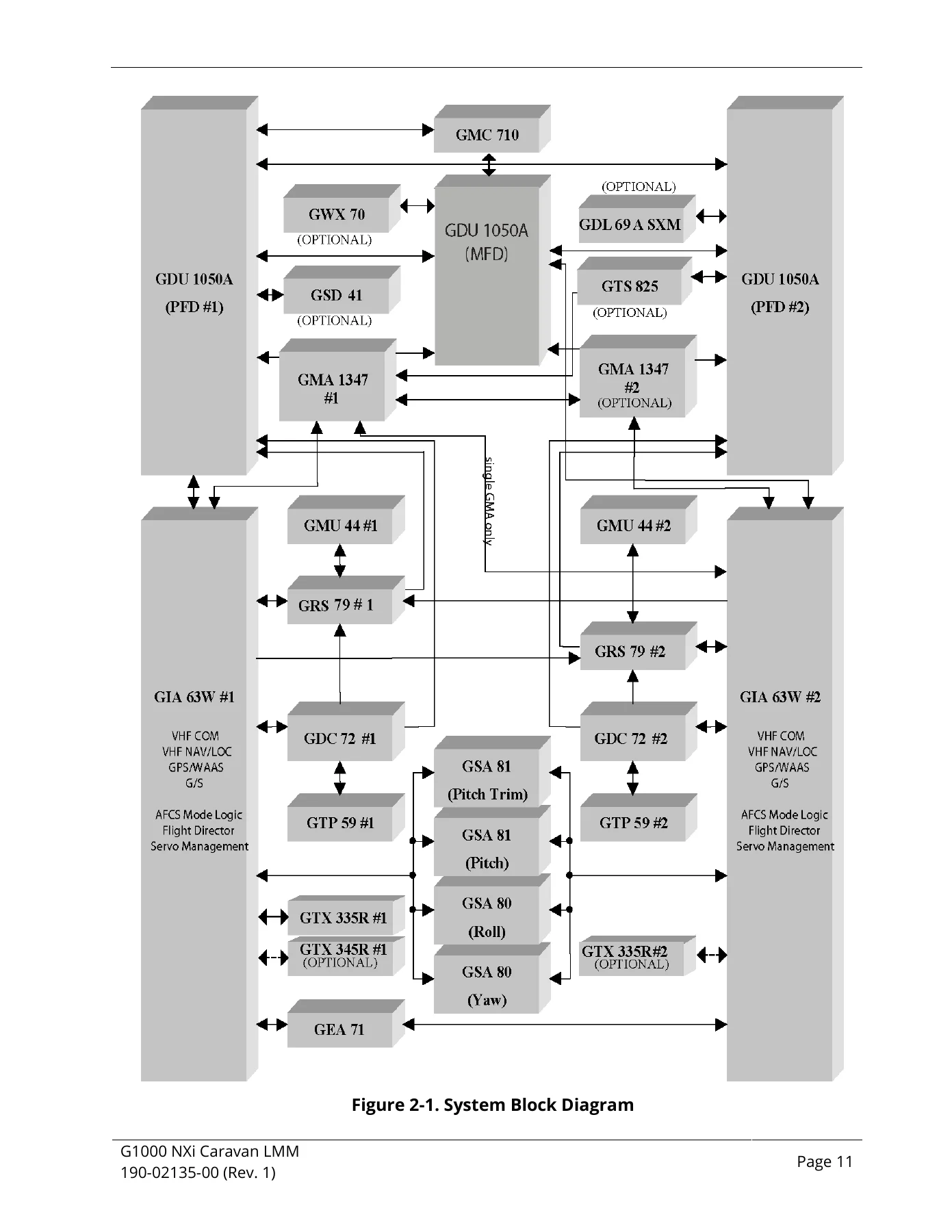
Because the Caravan G1000 NXi installation ties together two GIA 63W integrated avionics units, three GDU 1050A displays, dual GRS 79 AHRS and GMU 44 magnetometers, dual GDC 72 air data computers, the GMC 710 AFCS controller, GSA 80/81 servos and GSM 86 gearboxes, plus audio, transponder, datalink, traffic, radar and data concentrator options, the manual is built as a single integrated service document rather than a collection of unrelated LRU notes. Every procedure is written against the aircraft-level installation.
File Details
- Manual type: Avionics System Line Maintenance Manual
- Brand: Garmin
- Aircraft models: Cessna 208, Cessna 208B Caravan
- System: G1000 NXi Integrated Avionics System
- Document number: 190-02135-00
- Revision: Rev. 1
- Revision date: 4/4/2017 (Initial Release)
- Software reference: System Software 006-B2499-00 or later
- Language: English
- Page count: 310 pages
- File format: PDF
Chapters Covered
- 1 Introduction – Maintenance Philosophy, Related Documents, Garmin Technical Support, Manual Revision and Distribution
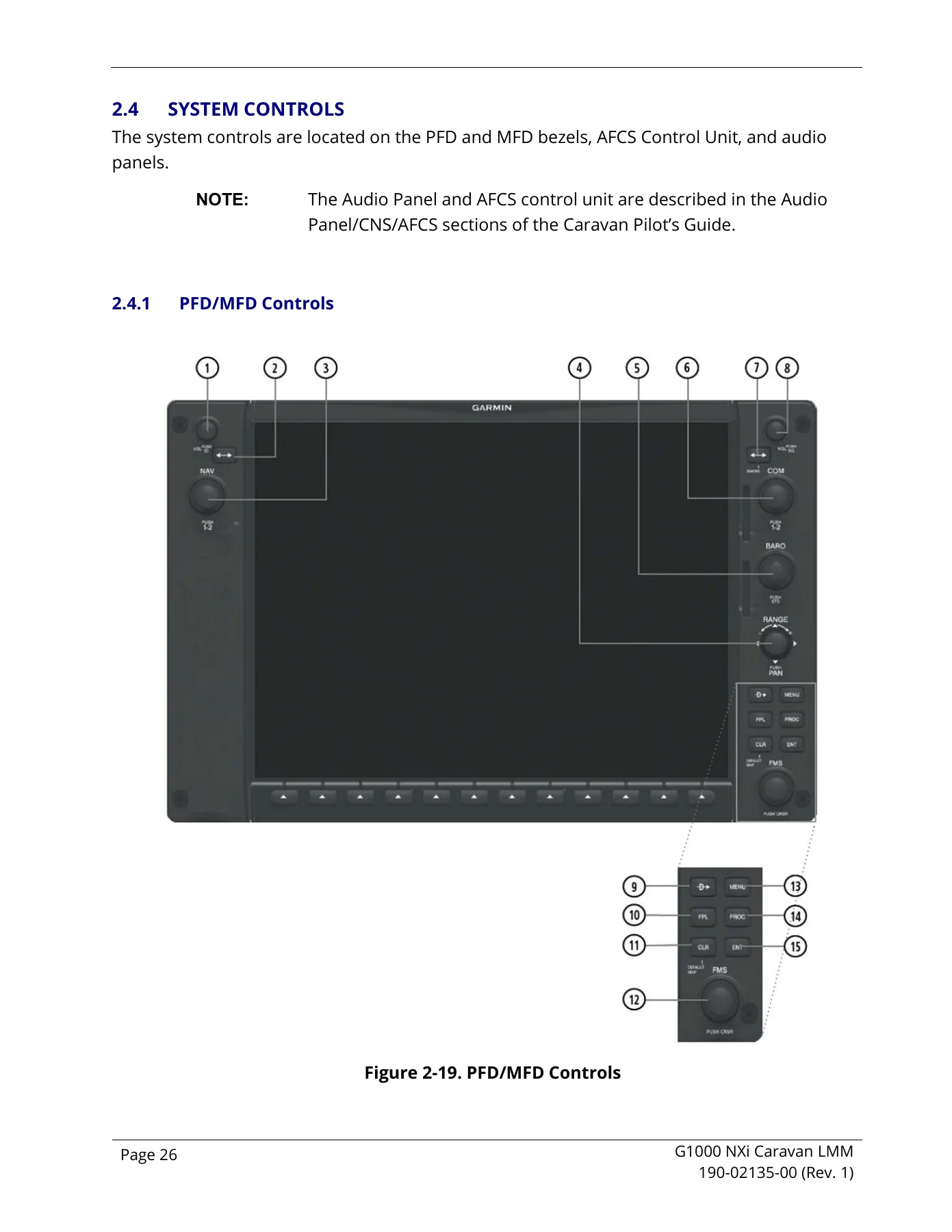
- 2 System Description – Standard Equipment, Optional Equipment, Line Replaceable Unit Descriptions, System Controls, Garmin AFCS Controls, GMA 1347 Audio Panel Controls, Softkey Function, FMS Knob
- 3 System Operation – System Power Up, Normal Display Operation, Reversionary Mode, Configuration Mode, SET>ACTV Configuration, Data Transmission Indicators, Configuration Mode Navigation, Software Files, Configuration File Descriptions and Storage, Loader Cards, Crossfill Monitoring System
- 4 System Software Loading and Configuration – Loading Software to the Displays, Loading Baseline System Software, Loading Software for Options, Optional Features Enablement (ChartView, GWX 70R Doppler/TD/GCS, SVS, Search and Rescue, TAWS, SurfaceWatch), Final Configuration Items
- 5 Troubleshooting – Unit Swapping, Visual Inspection, LRU Operational Status, System Display Annunciations, System Alert Window Messages, General System Troubleshooting, GFC Annunciations and Alerts, Downloading GIA and GSA Maintenance Logs, Assert Logs, ALTAIR ADAS/FAST Digital Engine Trend Monitoring
- 6 LRU Hardware Replacement – Accessing LRUs, Replacement Procedures for each LRU, GEA 71 Backshell Thermocouple Removal and Replacement
- 7 Reloading LRU Software and Configuration – Transaction Log Page, Reloading Procedures, Reloading Verification, Card Copy Management, Unit Exchange, LRU Testing
- 8 Periodic Maintenance – GWX 70R, GTS Processor, GDC 72, GEA 71, GMA 1347, GMC 710, GRS 79, GTX 335R/345R, GDL 69A SXM, GDU 1050A, GSA 80/81, GSM 86, GSA 80/81 Greasing, GSM Slip Clutch, GFC 700 Visual Inspection
- 9 Calibration Procedures – GRS 79/GMU 44 Calibration, GEA 71 High-Side Current Monitor Calibration, Optional COM Adjustment
Taken as a whole, the manual gives a technician a complete aircraft-level workflow rather than isolated LRU instructions. It starts with how the system is built and powered, moves through configuration mode and the SET and ACTIVE relationships that hold the aircraft-specific setup together, and then carries that foundation into software and option loading, fault isolation, hardware replacement, reloading, testing and calibration. Because the configuration architecture is explained before the service procedures, a technician can understand why a given LRU must be reloaded or reconfigured after replacement instead of treating each step as a disconnected task.
Systems and Line Replaceable Units Covered
The LRU descriptions and procedures span the full Caravan NXi fit. Standard equipment includes the GDC 72 Air Data Computer, GDU 1050A displays, GEA 71 Engine/Airframe Unit, GIA 63W GPS/WAAS/NAV/COM units, GMA 1347 Audio Panel, GMC 710 AFCS Control Unit, GMU 44 Magnetometer, GRS 79 AHRS, GSA 80 and GSA 81 Servo Actuators, GSM 86 Servo Gearbox, GTP 59 Outside Air Temperature Probe and GTX 335R Transponder. Optional equipment addressed in the same document includes the GDL 69A SXM SiriusXM Satellite Radio Data Link Receiver, GWX 70R Weather Radar, GTS Processor, GTX 345R Transponder, second GMA 1347 Audio Panel, GSD 41 Data Concentrator and GA 58 Antenna.
Hardware replacement procedures are given individually for the GDC 72, GDL 69A SXM, GDU 1050A, GEA 71, GIA 63W, GMU 44, GRS 79, GSA 80/81, GSM 86, GTS Processor, GTX 335R/345R, GTP 59, GMA 1347, GSD 41, GWX 70R, GMC 710 and the configuration modules, with unit part numbers and Garmin reference documents listed for each.
Software Loading, Configuration and Crossfill
A substantial part of the manual is devoted to getting software and configuration onto the aircraft correctly. It covers loading display software to the PFDs and MFD, loading baseline system software, loading software for installed options, and enabling optional features such as ChartView, GWX 70R Doppler, Turbulence Detection and Ground Clutter Suppression, Synthetic Vision System, Search and Rescue, TAWS and SurfaceWatch. The final configuration items include aircraft registration number entry, ICAO address and region, VFR code, the Configuration Manager confirmation, splash screen loading, database loading and clearing default user settings.
The crossfill monitoring system is documented in detail, including what happens when crossfill fails, times out, is cancelled after timeout, or completes after timeout, along with the specific causes and corrections for each case. For a system where a partial configuration upload can overwrite a correct configuration across the network, this section is what keeps a maintenance event from turning into a configuration mismatch across the aircraft.
Troubleshooting and Diagnostic Tools
The troubleshooting chapter is organized around the way faults actually present themselves in the aircraft. It covers visual inspection of SPIDER and shield block grounds, GDC 72, GEA 71, GMA 1347, GDU fans, GIA 63W, displays, GRS 79, GSA 80/81 and GSM 86, GMU 44, GTP 59, the GA 58 traffic antenna and the GMC 710. From there it moves into the Aux – System Status page, common failure annunciations, and the full system alert window message list with corrective actions for each message.
General system troubleshooting is broken out by subsystem, including GDU 1050A display faults, GPS reception, GMA 1347 audio, GEA 71 engine and airframe inputs, GDC 72 air data, the GFC 700 autopilot, AHRS behaviour and reversionary modes, COM transmit and receiver issues, the GDL 69A SXM datalink, and the GWX 70 weather radar. The GFC 700 material includes the pre-flight test, switch checks, clutch overpower checks, trim speed checks, autopilot operation checks, servo fault tables and the GIA pre-flight test steps. Procedures for downloading GIA and GSA maintenance logs and assert logs to an SD card are also included, along with the Altair ADAS/FAST digital engine trend monitoring message table.
Configuration pages are documented as diagnostic tools in their own right, with descriptions of the System Status, Date/Time Setup, System Upload, Transaction Log, Aircraft Configuration, Diagnostics Terminal, System Data Paths, System Setup, Manifest Configuration, Maintenance Log and Configuration Manager pages, plus the GDU, GIA, GEA, GTX 3×5, GRS, GDC, GFC, GMA, GDL, GWX, GTS and calibration page groups.
Calibration and Periodic Maintenance
The calibration chapter covers the GRS 79 and GMU 44 procedures in sequence: Pitch/Roll Offset (Procedure A1), Magnetometer Calibration (Procedure B), Heading Offset Compensation (Procedure C), Engine Run-Up Vibration Test (Procedure D) and Magnetometer Interference Test (Procedure E). Each is presented with its prerequisites, on-screen checklist flow and pass/fail criteria. The GEA 71 high-side current monitor calibration procedure and the optional COM squelch adjustment procedure are also included.
Periodic maintenance intervals are listed for the GTS Processor, GTX 335R/345R, GDL 69A SXM and other units, including visual inspection intervals, electrical bonding tests, post-lightning strike inspection, slip clutch checking and adjustment, GSA 80/81 greasing, and the GFC 700 visual inspection procedure. Slip clutch settings for the GSM 86 units fitted to the Caravan are tabulated by part number.
Get the G1000 NXi Caravan Manual and Work With Confidence
This Garmin G1000 NXi Cessna 208/208B Caravan Avionics Line Maintenance Manual supports the real jobs a Caravan avionics technician faces: loading and verifying system software, configuring the aircraft-specific parameters after an LRU change, diagnosing a flagged LRU or a red X on the displays, working through an alert window message to its corrective action, replacing a GIA, GRS, GDC, GEA, GMA, GDU, GSA, GSM, GTX, GDL, GWX, GTS or GSD unit, reloading software and configuration through the Transaction Log and LRU Replacement pages, and running the calibration procedures the GRS 79 and GMU 44 installation requires. It also carries the periodic maintenance intervals that keep the aircraft compliant over time.
Having the correct procedures and the correct configuration workflow matters because the G1000 NXi is a crossfilled, aircraft-level system. A configuration mismatch introduced by an incomplete upload or a partial reload can propagate across the network and leave the aircraft with the wrong setup. Working from the manufacturer’s own line maintenance procedures is what keeps software versions, configuration values, calibration data and enablement cards consistent across the whole installation.
IMAGES PREVIEW
Delivered as an instant PDF download, the manual is available immediately after purchase with no shipping and no waiting. It can be opened on a laptop, tablet or phone in the hangar, searched for a specific LRU or alert message, and printed for bench or cockpit use.

Reviews
There are no reviews yet.