
Crown ESR4500 Parts Manual PDF – 1.4t, 1.6t & 2.0t Reach Truck Spare Parts Catalog 812704-006
Original price was: $65.95.$40.95Current price is: $40.95.
Complete illustrated Crown ESR4500 spare parts catalog (doc 812704-006) for 1.4t, 1.6t and 2.0t reach trucks. Exploded views and part numbers for the full machine – 204 pages, instant PDF download.
Description
Crown ESR4500 Parts Manual – Illustrated Spare Parts Catalog for 1.4t, 1.6t and 2.0t Reach Trucks
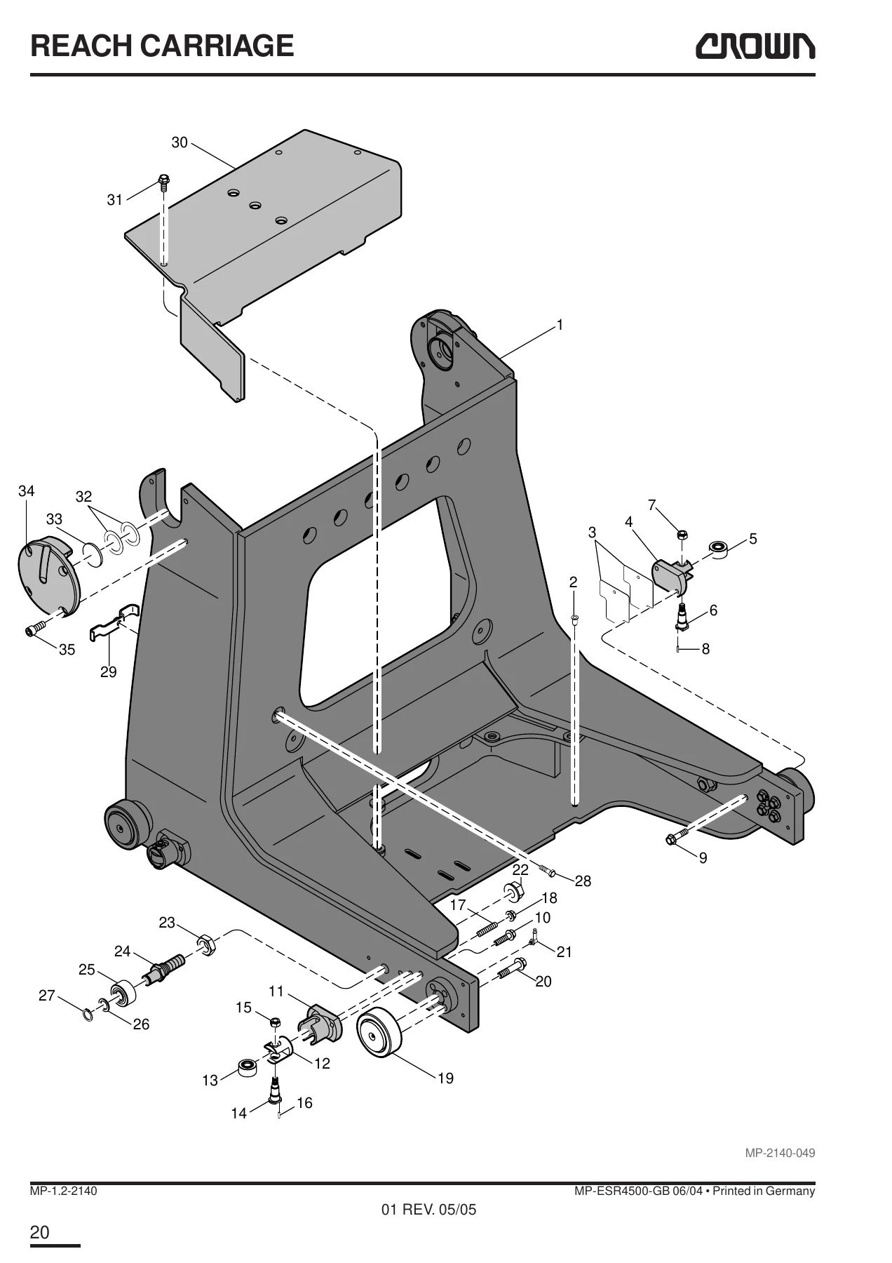
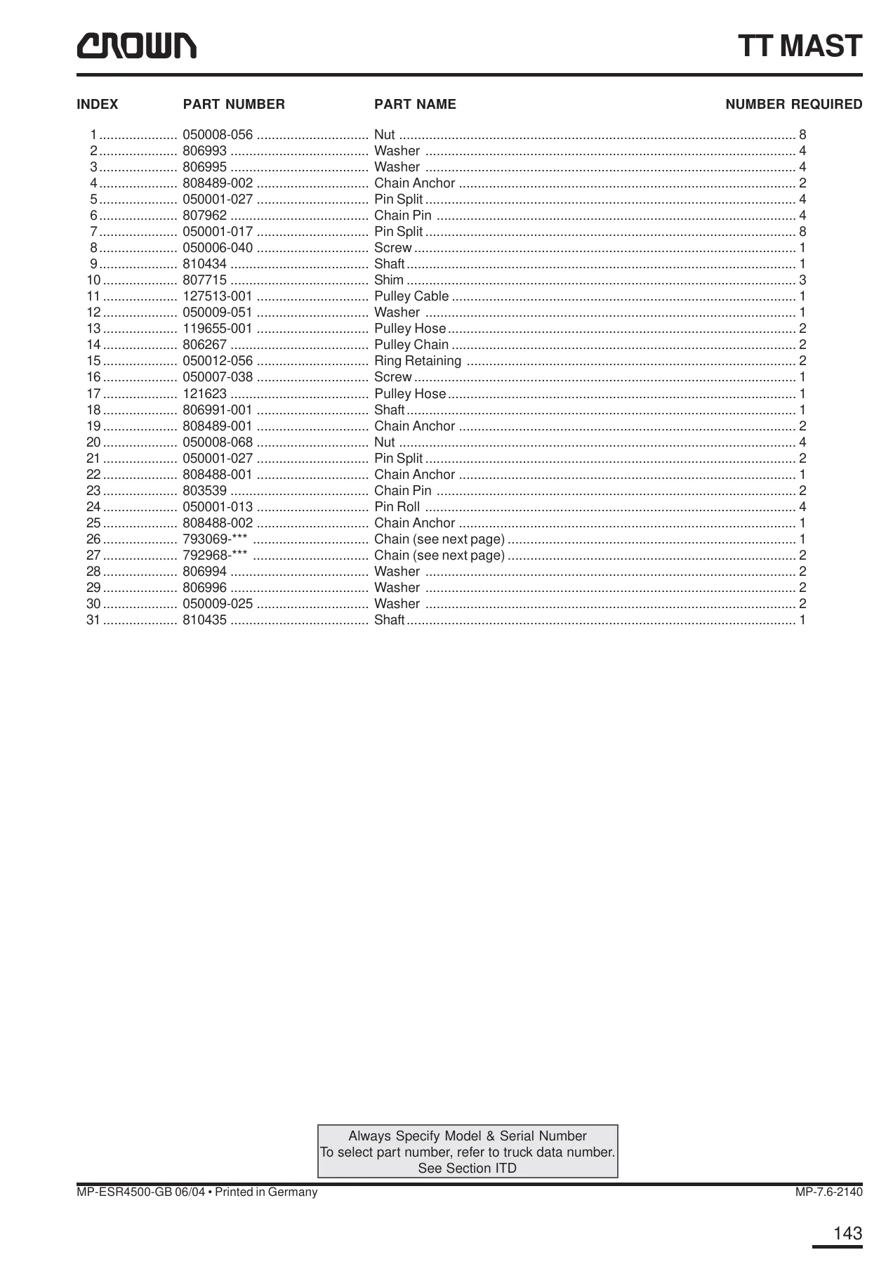
This is the complete Crown ESR4500 Parts Manual, published under document number 812704-006 and covering the ESR4500 reach truck in its 1.4t, 1.6t and 2.0t load classes. Every section is an illustrated parts breakdown: each assembly is presented as an exploded drawing with numbered callouts, and the accompanying list gives the index number, the Crown part number, the part name and the quantity required. That pairing of drawing and parts list is what makes the catalog genuinely usable at the counter or in the workshop – locate the assembly on the exploded view, read the index number, and order the exact component.
The contents run the full length of the machine: covers and carriage hardware, the hydraulic tank and valve block, the drive unit and gearbox, the electrical compartment and operator controls, the brake circuit, the steering column, the complete TT mast range, and the lift, free-lift and reach cylinders. Sections are divided by capacity and leg width throughout, so 1.4t, 1.6t and 2.0t trucks each get their own part numbers where they differ.
File Details
- Manual type: Illustrated Parts Manual (spare parts catalog)
- Brand and model: Crown ESR4500 reach truck
- Load classes covered: 1.4t, 1.6t and 2.0t
- Document number: 812704-006
- Language: English, with a French table of contents
- Page count: 204 pages
- File format: PDF
- Revision dates shown: Rev. 05/05, Rev. 11/05 and Rev. 02/06
- Publisher: Crown Gabelstapler GmbH & Co. KG, Munich, Germany
Chapters Covered
- Introduction
- Section 1 – Covers
- Section 2 – Hydraulic Part
- Section 3 – Drive Unit
- Section 4 – Electrical
- Section 5 – Brake System
- Section 6 – Steering
- Section 7 – Mast
- Section 8 – Cylinders
- Section 9 – Cabin / Plate – Forme
- Section 10 – Other Information
Section 1 – Covers
The bodywork and carriage hardware chapter. Exploded views cover the seat and pan assembly, armrest mouldings and pads, the overhead guard, rear mirror, guide wheels and accessories. Load wheel assemblies are broken down for both the 285 mm and 330 mm wheels, and the skid block and wear strip pages carry selection tables keyed to leg width – 1285 mm, 1425 mm and 1575 mm – and to freezer/corrosion specification. The battery lock and battery reach-out assemblies are drawn in full, including lever, link, springs and microswitch.
Section 2 – Hydraulic Part
Tube and hose layouts open the section, followed by the hydraulic tank with its suction filter, bonded seal and breather cap. The TT mast hydraulics, counter balance valves and hose assemblies are listed, then the valve block with its solenoids, lift/lower valve, pressure relief valve and filter, and the pump, pump motor and pump assembly with the bracket and coupling hardware.
Section 3 – Drive Unit
The drive unit chapter diagrams the drive plate, gearbox, drive motor, drive motor brake mounting, drive wheel, pinion, spacer and drive guard. Steering sensor assemblies and their inductive sensors, socket housings and crimps appear here for the trucks that use them, and the gearbox is drawn as a full exploded assembly.
Section 4 – Electrical
The largest section of the manual. It covers the electrical compartment, contactors, reach slowdown, HGTS lift speed reduction, height encoder and mast wiring, then the operator controls: joystick assemblies, dual-axis controls, the emergency disconnect switch and its actuator, direction switch and horn button, floorplate, accelerator and safety switch. DC/DC converters, control and display panels, warning lamps, travel and work contactors, reverse alarm, horn, connecting and mounting parts, and the cooling fan assemblies round out the chapter.
Section 5 – Brake System
Brake lines are listed individually by capacity and leg width, so the correct hose is easy to identify. The footbrake assembly is broken down to the pedal, rod fork, clevis pin, master cylinder and reservoir, and the drive motor brake assembly and load wheel brake – backplate, cylinder assemblies, brake shoes, springs and clamps – are drawn separately.
Section 6 – Steering
Steering motor assemblies are given for both the earlier and later builds, together with the coupling, speed reducer, steering column assembly, brake disc, bearings, shims and motor mounting hardware.
Section 7 – Mast
The mast chapter splits TT mast coverage into 1.4t/1.6t and 2.0t groups. Outer mast, first-stage and second-stage mast, lifting chain, tilt and sideshift, hydraulic tilt/sideshift, lift damping, fork tine, load backrest, guide pulleys and yoke each have their own illustrated pages. Collapsed-height tables run the full range from 2022 mm up to 4452 mm, with part numbers keyed to each height, so mast components can be matched to the truck’s exact build.
Section 8 – Cylinders
Cylinder coverage is broken out by capacity: lift cylinders for 1.4t/1.6t (40 mm) and for 2.0t (45 mm), free-lift cylinders (56 mm for 1.4t/1.6t and 65 mm for 2.0t), and the reach cylinder. Every cylinder is exploded to tube, piston rod, guide rings, seals, wipers, cap and bleed screw, with seal kits and collapsed-height tables listed for each variant.
Section 9 – Cabin / Plate – Forme
The freezer cabin chapter covers the heated windows and their rubber seals, the door lock assembly with handle, lever, locking wedge and bail, the manual and 12V windscreen wiper assemblies, and the relay, contactor, fuse holder and cover hardware that support the cold-store specification.
Section 10 – Other Information
The final section collects the decals and labels – Crown and Momentum decals, stand-on and stand-under warnings, moving mast and moving vehicle warnings, battery danger and charger hook-up labels, hydraulic oil label, serial number and capacity data plates, and a full set of info-point labels. Language variants for German, French, Spanish, Dutch, Italian, English and Portuguese are listed where applicable.
Order the Right Crown ESR4500 Part the First Time
Few things stall a reach truck faster than a wrong or missing part, and few things cause it more often than ordering from memory. This Crown ESR4500 parts manual removes the guesswork: it gives you the illustrated exploded views, the part numbers and the quantity required for every assembly on the truck, across all three load classes and every leg width. Whether you are rebuilding a load wheel, replacing a brake line, chasing an electrical fault in the joystick or emergency disconnect circuit, or re-hanging a mast chain, the illustration and the parts list sit together so you can move straight from diagnosis to order.
Because the catalog is organised by assembly rather than by part name, it also works as a reference when you strip a machine down – you can see how a component goes together before you take it apart, and note every fastener, shim, seal and clip you will need to put it back. That is exactly the kind of preparation that keeps a service job on schedule.
IMAGES PREVIEW
Delivered as an instant PDF download, the Crown ESR4500 parts manual opens on any device – desktop, laptop, tablet or phone – and every page can be printed for the workshop or the parts desk. There is no shipping and no waiting, so you can be reading the exploded view within moments of ordering.


Reviews
There are no reviews yet.