
CSI Series 200E CIHT Capping Machine Manual 200E-KH4252-24 #200E0121 – Operation, Maintenance, Troubleshooting & Parts Catalog PDF
Original price was: $67.95.$44.95Current price is: $44.95.
Complete CSI capping machine manual for Series 200E CIHT turret 200E-KH4252-24 (#200E0121) – safety, installation, cap feed setup, Magna Torq XT6 headset rebuild, lubrication schedules, troubleshooting and the full illustrated parts catalog in one PDF.
Description
The CSI Series 200E CIHT capping machine manual is the full documentation package issued with machine 200E-KH4252-24, serial #200E0121, built for FEMSA Villahermosa under sales order 57035 (1/11). It is the manual CSI instructs owners to store with the capping machine and keep available at the point of use at all times, and it reads exactly like what it is: a working document for the people who install, run, adjust and rebuild a 200/200E CIH capping tower. The body of the manual is printed in Spanish, with an English safety summary and the complete CSI XT6 Calibrated Headset manual at the rear.
File Details
- Manual type: Capping machine operation, maintenance, troubleshooting and parts manual
- Brand: Closure Systems International (CSI)
- Machine: Series 200E CIHT, 200E-KH4252-24, #200E0121
- Prepared for: FEMSA Villahermosa (Sales Order 57035 – 1/11)
- Language: Spanish and English
- Pages: 167
- Format: PDF
- Appendices: Magna Torq headset operating manual, cap orienter operating manual, electrical circuit diagrams, parts catalog and assembly drawings, OEM documentation
Chapters Covered
- 1.0 Estructura del Manual de Operación (Manual Structure)
- 2.0 Precauciones de Seguridad (Safety Precautions)
- 3.0 Peligros (Hazards)
- 4.0 Datos Técnicos (Technical Data)
- 5.0 Transporte y Empaque (Transport and Packaging)
- 6.0 Instalación (Installation)
- 7.0 Descripción Funcional (Functional Description)
- 8.0 Configuración, Verificaciones y Ajustes (Configuration, Checks and Adjustments)
- 9.0 Mantenimiento y Cuidado (Maintenance and Care)
- 10.0 Guía de Solución de Problemas (Troubleshooting Guide)
- 11.0 Instrucciones Eléctricas (Electrical Instructions)
- Appendices 1-5
1.0 Manual Structure, Notes and Terminology
The opening section explains how the document is organised, defines the warning and note conventions used throughout, and lays out the capping-specific vocabulary a new operator has to learn before touching the machine: cap chute, cap-in-head (CIH) station, cap releaser, cap stop cylinder, transfer star, centring star, infeed and discharge stars, centring guide, head load, and pick-up. It closes with a short design-application description of the Series 200/200E CIH machine, explaining that it is built for pre-formed plastic screw closures, that bottle handling parts are made for a specific container size and type, and that CSI should be consulted before adapting the capper to any other closure.
2.0-3.0 Safety Precautions and Hazards
These two sections are the ones CSI marks as mandatory reading before anyone is permitted near the machine, and they are treated here with the seriousness they deserve. Covered in detail: the stop procedure for electrical and pneumatic energy, lockout/tagout devices on the operator control box, the main electrical box and the pneumatic dump valve, the one-metre danger zone around the turret perimeter, personal protective equipment, housekeeping, electrical and maintenance safety, hearing protection guidance referenced to OSHA, and the owner’s own obligations for training and enforcing inspection frequency. There is also the reminder that interlock control circuits wired in yellow stay live even with the main disconnect off.
4.0-5.0 Technical Data, Transport and Packaging
The technical data chapter carries the product data block, dimensions and weights, electrical and pneumatic service requirements, component data, oils and greases, and general data. Visible general ratings include an ambient operating range of 58°F to 95°F, maximum 60% humidity, and a noise level of 75 dB(A) or below. The packaging chapter covers receiving inspection against the packing list, documenting transport damage, storage conditions from -20°C to +50°C in a closed dry place away from direct sunlight, and the instruction to reuse the original crate and packing material whenever the machine has to be shipped again.
6.0 Installation
Installation is written as a sequenced job: electrical supply line, compressed-air supply line, filtered air upstream of the machine, transport inside the plant, turret mounting on the filler, and orienter mounting. The lifting instructions are explicit that only the turret lifting lugs may be used, and that the cap orienter is raised only by its dedicated M16 lifting bolts. The chapter walks through removing the shipping bushing from the turret hub, sliding the column keyway over the base module key, threading the column into the height adjusting nut, aligning the rectangular hub key with the base drive sleeve, and clamping the turret at the correct height before the orienter is lowered onto the top plate and bolted down.
7.0 Functional Description
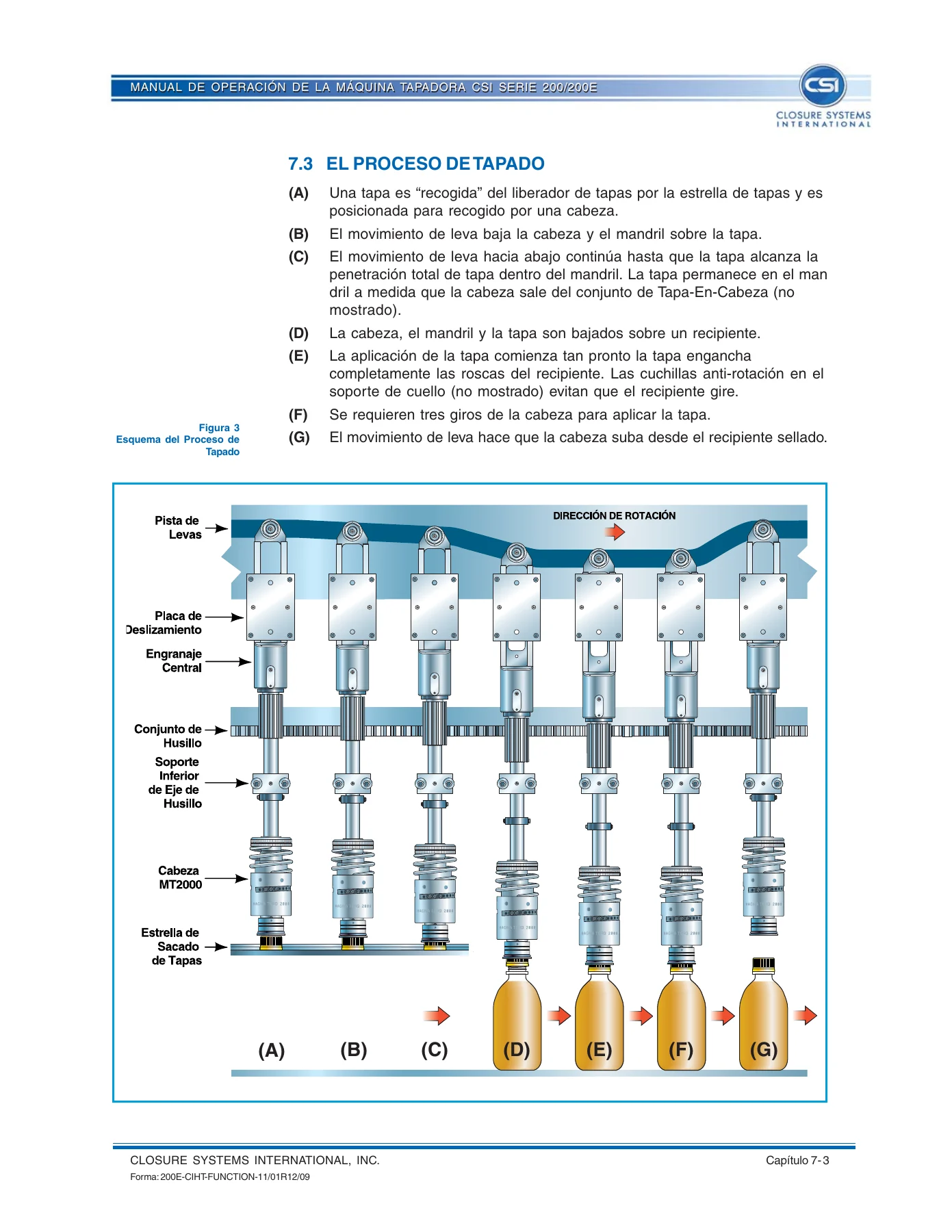
This is the section that actually explains how the capper works. A labelled component photograph identifies the SV20 cap orienter, cap chute, cap releaser, cam track, spindle assembly, head and cap-in-head assembly. The chapter then describes the drive path through the central column, the spindle and head assemblies carried in the guide sections of the turret cage, the spindle shaft gears running in constant mesh with the stationary central gear so the heads rotate continuously, the cam followers controlling vertical travel, and the magnetic clutch inside each head that slips once the preset torque is reached. The cap application sequence is broken into pick-up, mandrel penetration, descent onto the container, thread engagement, three head revolutions, and head rise off the sealed container.
8.0 Configuration, Checks and Adjustments
This chapter is where the manual earns its keep on a running line. It covers pre-start verification, checks before and during production, turret height adjustment using the synchronisation plug rather than a bottle, and the full cap feed assembly adjustment routine. The cap-in-head synchronisation procedure is given step by step: align a spacer gear drive pin with the cap star shaft, set a 1/16 in. clearance between the drive pin and the spacer gear at full engagement, release the clamp ring to index the spacer gear independently of the shaft, place a cap in a cap star cavity, rotate the star until the cap sits directly under a head mandrel, then set the spacer gear assembly vertically to leave 3/16 in. to 1/4 in. clearance under the turret casting before tightening. A separate set of instructions covers special closures that need an inner cap guide, including a 0.05-0.06 in. clearance check between the CIH drive pin and the spacer gear tooth root at four points 90 degrees apart.
9.0 Maintenance and Care
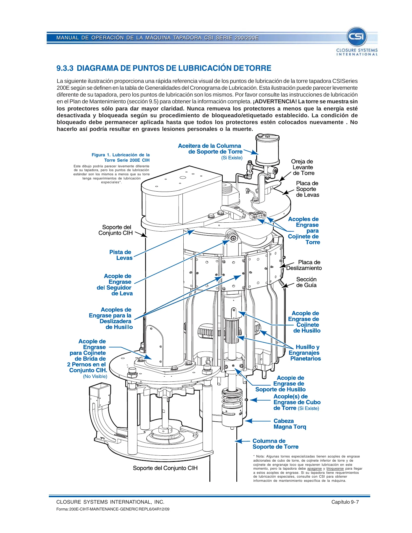
The maintenance chapter is organised around fixed intervals rather than vague advice. Cleaning, inspection and lubrication schedules are tabulated at 8, 24, 40, 160, 320, 1,000, 2,000 and 10,000 machine operating hours, with separate inspection and lubrication tables and a dedicated lubrication point diagram for the turret. The schedules specify aluminium complex food-grade grease for the spindle slide surfaces, spindle shaft lower support, cam followers, spindle drive gear teeth, turret bearings, central cam gear and cam track, and turret hub grease fittings, with 46 to 68 CST oil for the turret support column oiler and 460 CST gear oil for the SV20 reducer. Recommended lubricant manufacturers and product numbers are listed, together with a compatibility table that warns against mixing aluminium complex grease with incompatible thickeners, and a clear rule that non-food-grade petroleum lubricants must never be mixed with or substituted for food-grade lubricants. Cleaning instructions, approved cleaning substances, and disposal guidance for the machine, lubricants and waste products close the chapter.
10.0 Troubleshooting Guide
Written for plastic caps on plastic or glass bottles, this guide works through the real failure modes of a capping line with causes and corrections for each: cocked caps, broken, split or missing tamper-evident bands, low and high removal/incremental torque, leaking bottles, high caps, under-applied caps, cap back-off, upside-down caps, uncapped bottles, slow or interrupted cap feed, and cracked caps or split bands. Each fault is separated into cap causes, bottle causes and equipment causes, so a technician can eliminate the closure itself before dismantling the machine. The guide opens with a visual inspection checklist for correctly applied plastic closures and a systematic troubleshooting method: document the process, isolate one cause at a time, and revert any adjustment that did not fix the problem.
11.0 Electrical Instructions and Appendices
The electrical chapter is joined by five appendices: the Magna Torq headset operating manual, the cap orienter operating manual, electrical circuit diagrams, the parts catalog with assembly drawings, and OEM documentation. The parts catalog is extensive and fully illustrated, with exploded views and itemised bills of material for the spindle assembly, cap-in-head subassembly, pneumatic assembly, cap stop solenoid, cam, turret subassembly, neck star and guide components, cap chute assembly, cap stop assembly, turret guard panels and hardware down to individual dowel pins, washers and socket head cap screws. Part numbers are given for each item along with the quantity required.
Appendix 1 – CSI XT6 Calibrated Headset Manual (English)
The headset appendix is a complete manual in its own right and covers the XT6 magnetic clutch headset used on CSI Series 125, 200, 800C and 7000 capping machines. Adjustment procedures cover top load, static torque, and head rise. Top load is typically set between 35 and 45 lb, with the goal of running as light as possible without bottle rotation. Static torque is set to within plus or minus 0.5 in-lb across all heads on the machine, using either the MRA torque meter method with the headset removed or a torque wrench and chuck adapter with the headset still on the turret. Head rise is measured against the scribe lines on the upper housing, where each pair of lines represents 0.100 in. of travel, and is generally set between 0.120 and 0.200 in. per the closure manufacturer’s recommendation.
Inspection procedures give measurable wear limits rather than impressions: mounting hub outside diameter must not fall below 1.746 in., the span across two new drive pins must not fall below 2.010 in., upper housing bore must not exceed 1.757 in., and total side play between the mounting hub and upper housing measured at the bottom of the lower housing must not exceed 0.060 in. Bearing wear is checked two ways, with axial play not to exceed 0.020 in. on an assembled headset or 0.026 in. of inner race tilt on a removed bearing, and the bearing must turn freely with no drag or rough spots.
Daily maintenance is a hot water flush between 120°F and 200°F with the turret running, never a pressurised spray. The 6,000-hour rebuild covers complete disassembly, cleaning and inspection of the mounting hub and upper housing, replacement of the quad ring, drive pins, bearing, O-ring, upper and lower seals, and re-lubrication of every marked point with the specified greases and anti-seize compound. A 1,000-hour cycle applies instead for hot fill and aseptic packaging. Chuck wear is evaluated by applying a fresh closure to a bottle in the MRA torque meter and replacing the chuck if the closure strips at under 25 in-lb. Full disassembly and assembly procedures are given step by step with figures, along with the tool kit contents, torque values for the bearing lock ring, housings and headset-to-spindle joint, and an exploded parts view with part numbers.
Who This Manual Is For
This is written for the maintenance technician who has to set head rise and static torque, the operator who has to clear a jam and restart safely, the line engineer who has to change the capper over to a different bottle or closure, and the plant that has to order the right spindle, chuck, cap star or pneumatic valve the first time. It is equally useful for anyone bringing a used Series 200E capping tower back into service, because the installation, synchronisation and lubrication chapters describe the machine as a complete system rather than as a list of parts.
Machine-specific documentation for this exact turret is not the kind of thing you can improvise. A capping head set a few in-lb off produces leaking bottles, split tamper bands and torque complaints that never trace back to a single obvious cause, and a spacer gear indexed even slightly out of position produces uncapped bottles at speed. Having the factory synchronisation procedure, the cam follower and bearing wear limits, the lubrication intervals, and the illustrated parts breakdown for 200E-KH4252-24 in one place turns those problems into a diagnostic routine instead of a guessing game.
IMAGES PREVIEW
You get the complete CSI Series 200E CIHT capping machine manual as an instant PDF download. No shipping, no waiting on a printed binder, no missing pages. Open it on a laptop at the machine, on a tablet at the bench, or print the chapters you need for the shift and leave them in the tool crib. Every section, every table and every assembly drawing is exactly as issued for this machine.


Reviews
There are no reviews yet.