
Cummins B3.9 B5.9 Troubleshooting & Repair Manual PDF Download
Original price was: $49.95.$29.95Current price is: $29.95.
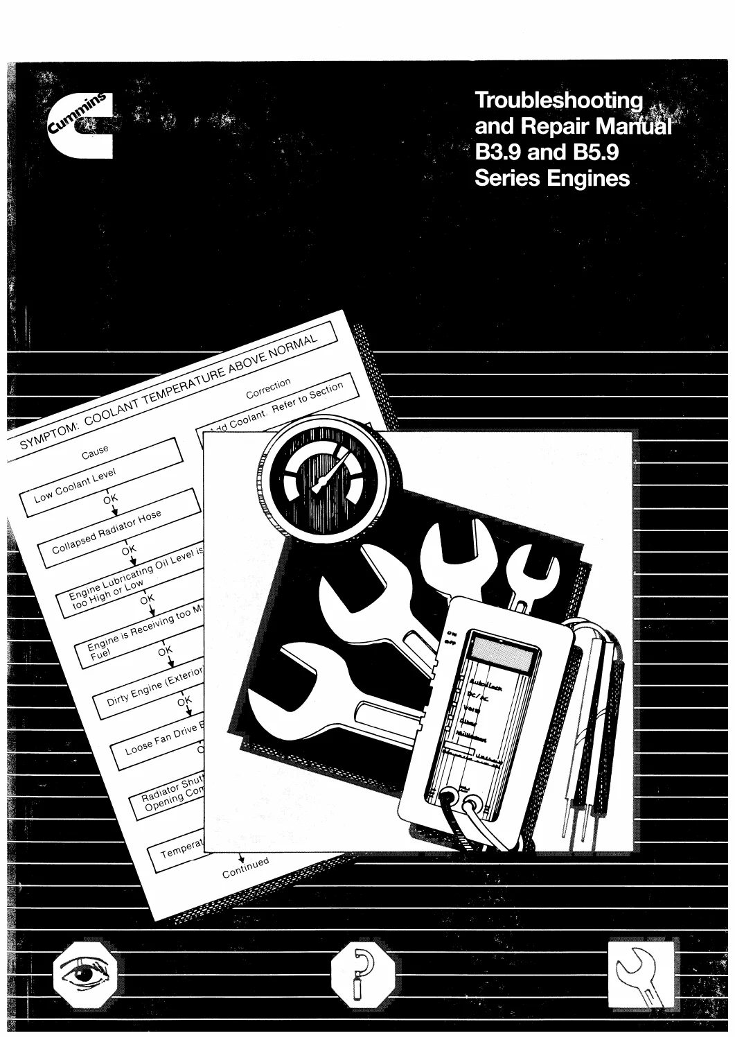
Cummins b3.9 b5.9 troubleshooting and repair manual covering B3.9 Series Engines, B5.9 Series Engines. 936-page PDF with Introduction, Engine Identification, Troubleshooting Symptoms, Complete Engine — Group 00 and detailed service/reference material.
Description
B3.9 and B5.9 Fault Finding in One Repair Volume
The 936-page Cummins B3.9 and B5.9 volume is built around a practical diagnosis path: identify the symptom, work through probable causes, then turn to the referenced corrective procedure. It is specifically a troubleshooting and in-chassis repair manual for B3.9 and B5.9 Series Engines, with Section V carrying system specifications and torque values.
How the Manual Moves From Symptom to Repair
The document identifies the following applicability or named equipment:
- B3.9 Series Engines
- B5.9 Series Engines
Engine-System Groups Covered
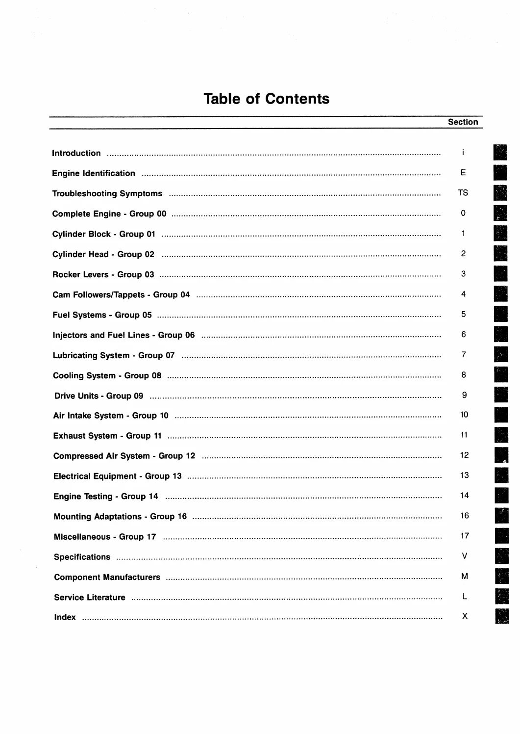
The manual is organised around these top-level sections and repair groups:
- Introduction
- Engine Identification
- Troubleshooting Symptoms
- Complete Engine — Group 00
- Cylinder Block — Group 01
- Cylinder Head — Group 02
- Rocker Levers — Group 03
- Cam Followers/Tappets — Group 04
- Fuel Systems — Group 05
- Injectors and Fuel Lines — Group 06
- Lubricating System — Group 07
- Cooling System — Group 08
- Drive Units — Group 09
- Air Intake System — Group 10
- Exhaust System — Group 11
- Compressed Air System — Group 12
- Electrical Equipment — Group 13
- Engine Testing — Group 14
- Mounting Adaptations — Group 16
- Miscellaneous — Group 17
- Specifications
- Component Manufacturers
- Service Literature
- Index
Repairs, Tests and Measurements Supported
Across those sections, the work is centred on the following systems and service subjects:
- symptom-tree diagnosis that links probable causes to corrective procedures
- engine identification and dataplate information
- in-chassis engine repair procedures
- cylinder block and cylinder head service
- rocker lever and tappet service
- fuel injection, fuel transfer and injector-line checks
- lubricating-oil system inspection and pressure control
- cooling-system testing and thermostat data
- air-intake and exhaust checks
- compressed-air equipment
- electrical equipment and starting-system data
- engine testing, mounting adaptations and component torque values
- system specifications and service-tool references
Practical tasks supported by the procedures include:
- locating a complaint in the Troubleshooting Symptoms section and following the probable-cause tree to the referenced repair procedure
- fuel-transfer-pump output-pressure checks and fuel-system air/restriction diagnosis
- fuel-injection pump timing and removal references
- lubricating-oil pressure diagnosis and pressure-regulating-valve checks
- cooling-system air/combustion-gas testing
- cylinder-block, cylinder-head and rocker-lever inspections
- engine blowby measurement and test-gauge setup
- electrical measurements and starting-system checks
- torque-value lookup in Section V
- in-chassis removal, installation, cleaning, inspection and adjustment procedures across engine systems
Selected Service Specifications
Among the measurable values and reference points printed in the manual are:
- Rocker lever overhead set — intake clearance: 0.254 mm [0.010 in]
- Rocker lever overhead set — exhaust clearance: 0.508 mm [0.020 in]
- Lubricating-oil pressure-regulating valve opens above 449 kPa [65 psi]
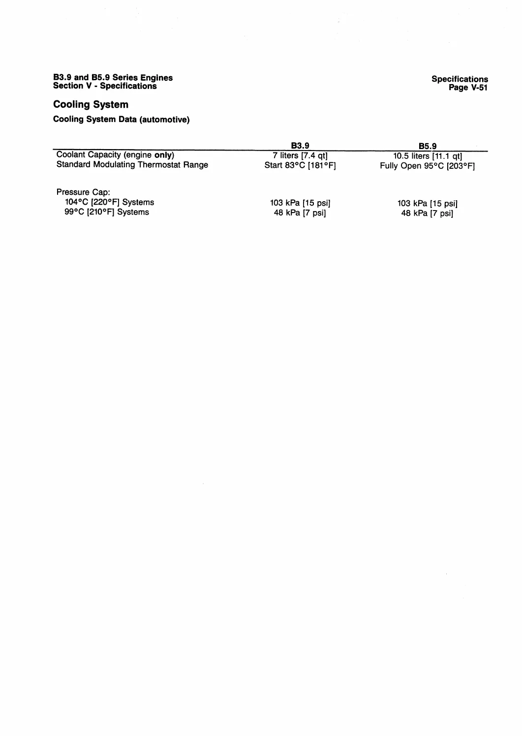
- Standard modulating thermostat: starts 83°C [181°F], fully open 95°C [203°F]
- Pressure cap for 104°C [220°F] systems: 109 kPa [15 psi]
- Pressure cap for 99°C [210°F] systems: 48 kPa [7 psi]
- 12-V minimum battery capacity with light accessories: B3.9 625 CCA; B5.9 800 CCA
- 24-V minimum battery capacity with light accessories: B3.9 400 CCA; B5.9 400 CCA
- 12-V minimum battery capacity with heavy accessories: B3.9 800 CCA; B5.9 950 CCA
- 24-V minimum battery capacity with heavy accessories: B3.9 400 CCA; B5.9 475 CCA
For buyers comparing this manual with a shorter overview, the depth comes from the way its named sections connect to real workshop subjects. Introduction is part of the documented coverage, alongside symptom-tree diagnosis that links probable causes to corrective procedures. Engine Identification is part of the documented coverage, alongside engine identification and dataplate information. Troubleshooting Symptoms is part of the documented coverage, alongside in-chassis engine repair procedures. Complete Engine — Group 00 is part of the documented coverage, alongside cylinder block and cylinder head service. Cylinder Block — Group 01 is part of the documented coverage, alongside rocker lever and tappet service. Cylinder Head — Group 02 is part of the documented coverage, alongside fuel injection, fuel transfer and injector-line checks. Rocker Levers — Group 03 is part of the documented coverage, alongside lubricating-oil system inspection and pressure control. Cam Followers/Tappets — Group 04 is part of the documented coverage, alongside cooling-system testing and thermostat data. Fuel Systems — Group 05 is part of the documented coverage, alongside air-intake and exhaust checks. Injectors and Fuel Lines — Group 06 is part of the documented coverage, alongside compressed-air equipment. Lubricating System — Group 07 is part of the documented coverage, alongside electrical equipment and starting-system data. Cooling System — Group 08 is part of the documented coverage, alongside engine testing, mounting adaptations and component torque values. Drive Units — Group 09 is part of the documented coverage, alongside system specifications and service-tool references. Air Intake System — Group 10 is part of the documented coverage, alongside symptom-tree diagnosis that links probable causes to corrective procedures. Exhaust System — Group 11 is part of the documented coverage, alongside engine identification and dataplate information. Compressed Air System — Group 12 is part of the documented coverage, alongside in-chassis engine repair procedures. Electrical Equipment — Group 13 is part of the documented coverage, alongside cylinder block and cylinder head service. Engine Testing — Group 14 is part of the documented coverage, alongside rocker lever and tappet service. Mounting Adaptations — Group 16 is part of the documented coverage, alongside fuel injection, fuel transfer and injector-line checks. Miscellaneous — Group 17 is part of the documented coverage, alongside lubricating-oil system inspection and pressure control. Specifications is part of the documented coverage, alongside cooling-system testing and thermostat data. Component Manufacturers is part of the documented coverage, alongside air-intake and exhaust checks. Service Literature is part of the documented coverage, alongside compressed-air equipment. Index is part of the documented coverage, alongside electrical equipment and starting-system data. The coverage is therefore not limited to a single repair operation; it follows the document’s own section structure and keeps related inspection, adjustment and reference material in the same PDF.
The procedures also show the kinds of jobs for which the manual can be kept open beside the equipment. A technician can use the manual for locating a complaint in the Troubleshooting Symptoms section and following the probable-cause tree to the referenced repair procedure. A technician can use the manual for fuel-transfer-pump output-pressure checks and fuel-system air/restriction diagnosis. A technician can use the manual for fuel-injection pump timing and removal references. A technician can use the manual for lubricating-oil pressure diagnosis and pressure-regulating-valve checks. A technician can use the manual for cooling-system air/combustion-gas testing. A technician can use the manual for cylinder-block, cylinder-head and rocker-lever inspections. A technician can use the manual for engine blowby measurement and test-gauge setup. A technician can use the manual for electrical measurements and starting-system checks. A technician can use the manual for torque-value lookup in Section V. A technician can use the manual for in-chassis removal, installation, cleaning, inspection and adjustment procedures across engine systems. These are the actual work areas represented in the document, so the buyer can use the manual to move from component identification into the relevant removal, inspection, adjustment, test or installation material without substituting an unrelated model reference.
Reference values matter most when a repair reaches the checking stage. The reference data includes Rocker lever overhead set — intake clearance: 0.254 mm [0.010 in]. The reference data includes Rocker lever overhead set — exhaust clearance: 0.508 mm [0.020 in]. The reference data includes Lubricating-oil pressure-regulating valve opens above 449 kPa [65 psi]. The reference data includes Standard modulating thermostat: starts 83°C [181°F], fully open 95°C [203°F]. The reference data includes Pressure cap for 104°C [220°F] systems: 109 kPa [15 psi]. The reference data includes Pressure cap for 99°C [210°F] systems: 48 kPa [7 psi]. The reference data includes 12-V minimum battery capacity with light accessories: B3.9 625 CCA; B5.9 800 CCA. The reference data includes 24-V minimum battery capacity with light accessories: B3.9 400 CCA; B5.9 400 CCA. The reference data includes 12-V minimum battery capacity with heavy accessories: B3.9 800 CCA; B5.9 950 CCA. The reference data includes 24-V minimum battery capacity with heavy accessories: B3.9 400 CCA; B5.9 475 CCA. The figures belong to the same manual as the procedures above, which makes them useful for verifying the documented setup, limit, clearance, pressure, dimension, torque or operating condition where that type of value is supplied.
Document Details
- Manual type: Troubleshooting and Repair
- Brand / model: Cummins — B3.9 and B5.9 Series Engines
- Language: English
- Page count: 936
- File format: PDF
- Document number: Bulletin No. 3666087-01
- Publication / issue: Printed 10/99
Put the Diagnostic Path Beside the Engine
When a B3.9 or B5.9 presents a symptom, this manual lets you move from the troubleshooting tree into the exact engine-system procedure, then verify the result against Cummins specifications and torque data. That connection between cause, corrective action and measured value is what makes the correct manual useful during real diagnosis. Your PDF becomes available as an instant download immediately after payment completes—no shipping and no delay—and can be read on a phone, tablet, laptop or workshop PC or printed for the job.
Reviews
There are no reviews yet.