
Cummins K19 KT KTA19 KTTA19 Diesel Engine Shop Manual Kit – July 1985 PDF
Original price was: $49.95.$29.95Current price is: $29.95.
Complete Cummins K19 diesel engine shop manual covering disassembly, inspection, rebuilding, repair, assembly, adjustment, system service and engine testing for the K19 family, including KT, KTA19 and KTTA19 configurations. Bulletin No. 3810258, printed July 1985, supplied as a 598-page PDF.
Description
Cummins K19 KT KTA19 KTTA19 Diesel Engine Shop Manual Kit – July 1985 PDF
This Cummins K19 KT KTA19 KTTA19 Diesel Engine Shop Manual Kit – July 1985 PDF is a detailed workshop reference for major service and rebuilding of the Cummins K19 engine family. The manual states that it contains the complete disassembly, rebuild and assembly instructions for the K19 engine and is arranged for use in a shop environment with the engine mounted on an approved rebuild stand. The introductory material identifies KT and KTA19 engines together with the KTTA19, while the manual itself is organized throughout around the K19 engine platform.
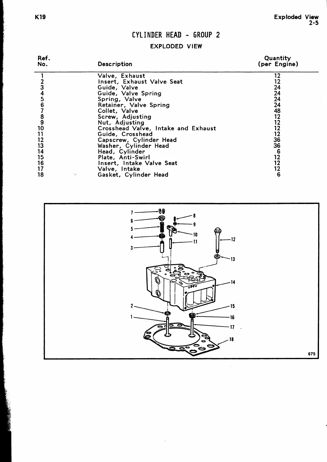
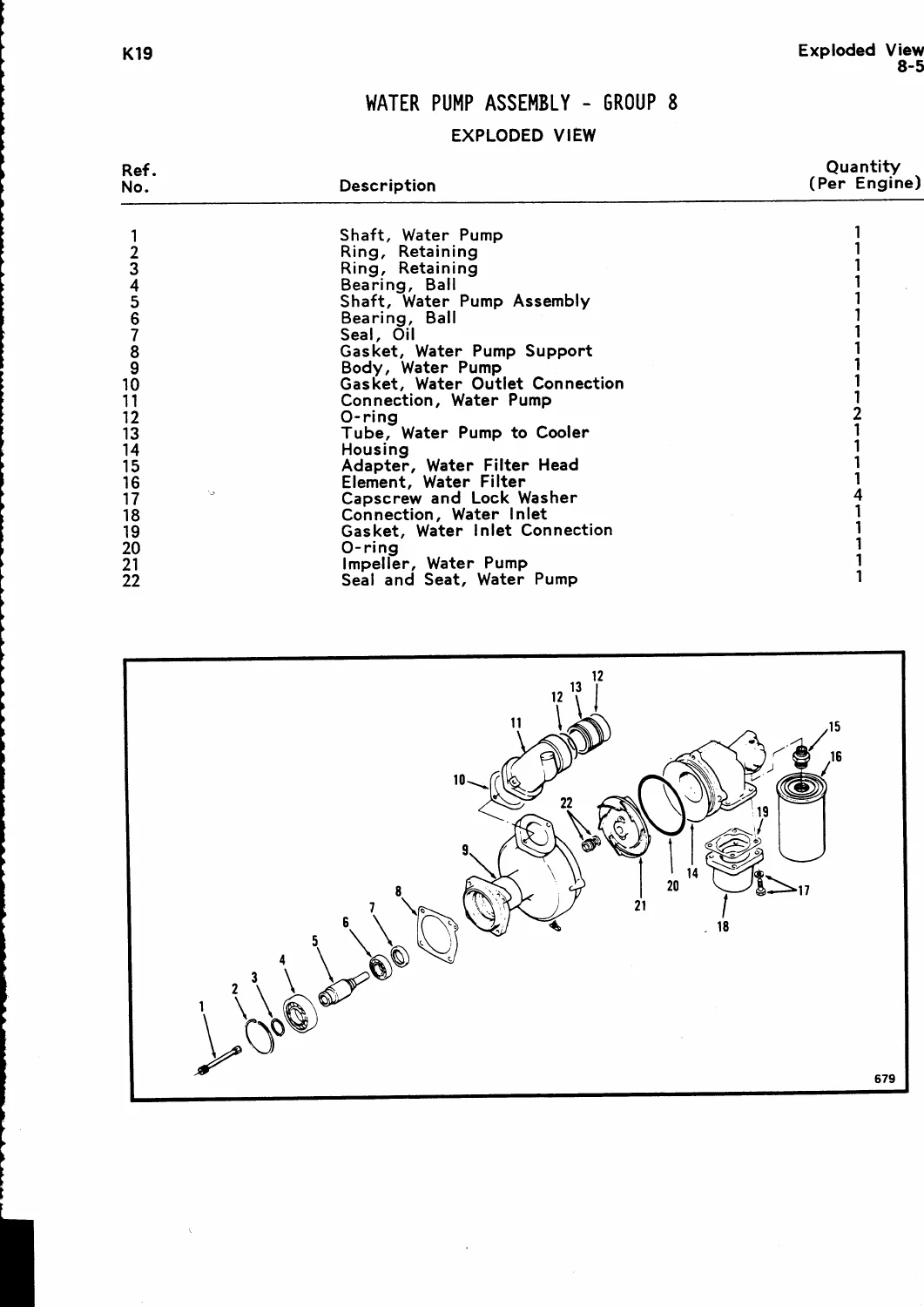
This is considerably more than a basic maintenance guide. Its group-based structure follows the engine from complete teardown through component inspection and repair to reassembly and testing. Individual procedures cover removal, installation, cleaning, dimensional checks, magnetic crack inspection, machining operations, replacement of bushings and bearings, rebuilding of assemblies, adjustment, torque requirements and checks for reuse. Exploded views and service-tool references are included throughout the major groups to support practical workshop work.
Built Around a Complete Engine Rebuild
The opening engine disassembly and assembly group provides the framework for stripping and rebuilding the complete engine. Procedures address major components including the cylinder head, cam followers, rocker lever assemblies, crankshaft, camshaft, pistons and connecting rods, cylinder liners, front gear train, lubricating oil components, cooling components, fuel system parts, turbocharger connections, accessory drives, flywheel and flywheel housing.
The manual does not treat inspection as an afterthought. Cummins explains that the specified inspections are intended to minimize unnecessary replacement of serviceable parts. Dedicated component sections therefore include cleaning and inspection instructions, reuse checks, service limits and repair procedures alongside the basic removal and installation sequence. General instructions also cover shop safety, cleaning by solvent, acid, steam and glass bead methods, repair practices, fasteners and torque guidance.
Component Inspection, Machining and Reconditioning
The cylinder block section contains substantial rebuild information for the internal structure of the K19. Coverage includes the cylinder block, cylinder liners, liner packing-ring areas, counterbores, crankshaft, connecting rods and bearings, camshaft, camshaft bushings and gears, gear cover and related components. Procedures include cleaning and checking parts for reuse, crankshaft straightness checks, magnetic crack inspection and component-specific repair work.
Block-related procedures extend into operations such as checking cylinder block counterbore concentricity, machining counterbore depth for shims and machining for oversize liners. The cylinder head group separately addresses crossheads, valves, valve guides, valve-seat work and related inspection and reconditioning. This makes the Cummins K19 diesel engine shop manual useful when a rebuild requires measurement and corrective work rather than simple parts replacement.
Valve Train, Fuel and Injection Coverage
Dedicated groups cover rocker levers and cam followers. Rocker lever information includes the lever assembly, shafts, adjusting screws, bushings, covers, housings, crankcase breather arrangements, magnetic crack checking and rebuilding. The cam follower section covers the follower assembly, shafts, sockets, rollers, push rods and covers, including cleaning, inspection, rebuilding and replacement procedures.
Fuel-system coverage includes the fuel pump and fuel filter head, with procedures for cleaning, reuse inspection, rebuilding and fuel-pump calibration. The injectors and fuel-lines group adds injector service, fuel tubes, fuel manifold components and Hydraulic Variable Timing (HVT) equipment. HVT material includes the fuel-pressure switch, oil-control valve, oil manifold, pressure-relief valve and wiring harness. The manual also contains engine-specific notes for certain configurations, including references to KTA19-C engines and KTTA engines where particular hardware or procedures differ.
Lubrication, Cooling, Drives, Intake and Exhaust
The lubricating-system group covers the oil pan, dipstick information, oil suction tube, lubricating oil cooler elements, oil filter head and lubricating oil pump. Exploded views, general information, cleaning and inspection, rebuilding and component replacement procedures are provided where applicable.
Cooling-system coverage includes the water pump, water-pump bearings, water-pump outlet connection, water bypass tube and connection, thermostat and thermostat housing, fan hubs, fan-idler assemblies and engine fans. The manual gives system operating information as well as service procedures, allowing the technician to work on individual cooling components while understanding their relationship to overall engine cooling.
The drive-units group addresses the fuel pump/air-compressor drive, hydraulic-pump drive, barring mechanism, accessory-drive pulleys and alternator or water-pump drive pulleys. Procedures include exploded views, rebuilding, checking for reuse, gear or shaft replacement, wear-sleeve replacement and bushing work.
Air-intake material covers the aftercooler assembly and water tubes, air crossover and tubing, air connections and turbocharger inspection. The exhaust section covers exhaust-manifold construction and rebuilding, including information relating to the wet exhaust manifold. Air-equipment information directs technicians to the appropriate dedicated air-compressor rebuild information where the complete compressor procedure is outside this manual.
Electrical Equipment, Testing and Installation Details
The electrical-equipment group includes the alternator adjusting link, alternator bracket and starter motor, with inspection and reuse procedures supported by general information. Engine testing is treated as a separate major group and includes specifications, engine run-in procedures without a dynamometer, with a chassis dynamometer and with an engine dynamometer. The same area also covers engine painting and short-term and long-term storage.
Mounting adaptations include flywheel, ring gear and flywheel-housing information, with procedures relating to flywheel-housing alignment and redoweling to the cylinder block. The final vehicle-braking group contains Jacobs Engine Brake information and references to K-1150 and K-1200 material included in the shop-manual kit.
File Details
- Manual type: Shop Manual / Engine Rebuild and Repair Manual
- Brand: Cummins
- Engine family: K19
- Models identified: KT, KTA19 and KTTA19
- Language: English
- Page count: 598 pages
- File format: PDF
- Bulletin number: 3810258
- Publication date: Printed July 1985
Chapters Covered
- Introduction
- How to use the manual, engine identification, safety, symbols, illustrations, cleaning, general repair instructions and general specifications
- Group 0 – Engine Disassembly and Assembly
- Complete engine teardown, component removal, preparation and engine reassembly procedures
- Group 1 – Cylinder Block
- Cylinder block, counterbores, cylinder liners, crankshaft, connecting rods, bearings, camshaft, bushings, gears and gear-cover components
IMAGES PREVIEW

- Group 2 – Cylinder Head
- Crossheads, valves, valve guides, valve seats, inserts and cylinder-head rebuilding operations
- Group 3 – Rocker Levers
- Rocker lever assembly, bushings, shafts, adjusting screws, covers, housings and crankcase breather
- Group 4 – Cam Followers
- Cam follower assemblies, shafts, sockets, rollers, push rods and covers
- Group 5 – Fuel System
- Fuel pump, calibration, rebuild procedures and fuel filter head
- Group 6 – Injectors and Fuel Lines
- Injectors, fuel tubes, fuel manifold and Hydraulic Variable Timing components
- Group 7 – Lubricating System
- Oil pan, suction tube, oil cooler elements, oil filter head and lubricating oil pump
- Group 8 – Cooling System
- Water pump, bearings, thermostat, thermostat housing, fan hubs, fan idler and cooling-system information
- Group 9 – Drive Units
- Fuel pump/air-compressor drive, hydraulic-pump drive, barring mechanism and drive pulleys
- Group 10 – Air Intake System
- Aftercooler, aftercooler water tubes, air crossover, air connections and turbocharger
- Group 11 – Exhaust System
- Exhaust manifold, exploded view, general information and rebuild coverage
- Group 12 – Air Equipment
- Air-equipment information and air-compressor service references
- Group 13 – Electrical Equipment
- Alternator adjusting link, alternator bracket and starter motor
- Group 14 – Engine Testing
- Specifications, engine run-in with several test arrangements, painting and engine storage
- Group 16 – Mounting Adaptations
- Flywheel, ring gear, flywheel housing and housing-to-block alignment/redoweling
- Group 20 – Vehicle Braking
- Jacobs Engine Brake information and K-1150/K-1200 related material
Taken as a whole, the Cummins K19 KT KTA19 KTTA19 Diesel Engine Shop Manual Kit – July 1985 PDF provides the procedural sequence and workshop data needed to move from full engine disassembly into detailed component inspection, repair and reconditioning, then through assembly, adjustment and final engine testing. The combination of exploded views, special-tool references, measurements, inspection criteria, torque information and component-level rebuild procedures makes it particularly suited to substantial K19 engine work.
Carry Out K19 Engine Repairs with the Correct Procedures at Hand
Whether the job involves a complete K19 overhaul, cylinder block or cylinder head reconditioning, valve-train work, fuel and injection service, lubrication or cooling-system repairs, drive-unit rebuilding, turbocharger and aftercooler work, flywheel-housing alignment or post-rebuild engine testing, this Cummins K19 shop manual gives the technician the procedures and specifications needed to work systematically. Using the documented inspection, assembly, adjustment and torque information helps avoid relying on memory or improvised settings during major engine work.
Your manual is supplied as an instant PDF download after purchase. There is no physical book and no shipping delay. Open it on a computer, tablet or compatible mobile device, keep it available in the workshop, and print the pages or procedures you need for the job.
Reviews
There are no reviews yet.