Daewoo Doosan Forklift BC15T, BC18T, BC20T Electric Lift Trucks MicroController Control System Manual
$24.95
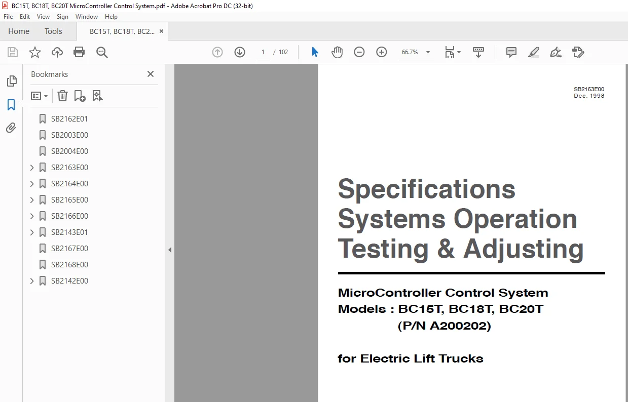
Daewoo Doosan Forklift BC15T, BC18T, BC20T Electric Lift Trucks MicroController Control System Manual – PDF DOWNLOAD
(P/N A200202)
Description
Daewoo Doosan Forklift BC15T, BC18T, BC20T Electric Lift Trucks MicroController Control System Manual – PDF DOWNLOAD
FILE DETAILS:
Daewoo Doosan Forklift BC15T, BC18T, BC20T Electric Lift Trucks MicroController Control System Manual – PDF DOWNLOAD
Language :English
Pages :102
Downloadable : Yes
File Type : PDF
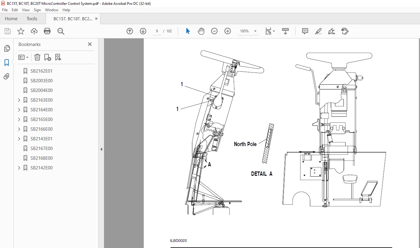
IMAGES PREVIEW OF THE MANUAL:
DESCRIPTION:
Daewoo Doosan Forklift BC15T, BC18T, BC20T Electric Lift Trucks MicroController Control System Manual – PDF DOWNLOAD
Important Safety Information
Most accidents involving product operation, maintenance and repair are caused by failure to observe basic safety
rules or precautions. An accident can often be avoided by recognizing potentially hazardous situations before an
accident occurs. A person must be alert to potential hazards. This person should also have the necessary
training, skills and tools to perform these functions properly.
Read and understand all safety precautions and warnings before operating or performing lubrication,
maintenance and repair on this product.
Basic safety precautions are listed in the ÒSafetyÓ section of the Service or Technical Manual. Additional safety
precautions are listed in the ÒSafetyÓ section of the owner/operation/maintenance publication.
Specific safety warnings for all these publications are provided in the description of operations where hazards
exist. WARNING labels have also been put on the product to provide instructions and to identify specific hazards.
If these hazard warnings are not heeded, bodily injury or death could occur to you or other persons. Warnings in
this publication and on the product labels are identified by the following symbol.
TABLE OF CONTENTS:
Daewoo Doosan Forklift BC15T, BC18T, BC20T Electric Lift Trucks MicroController Control System Manual – PDF DOWNLOAD
(P/N A200202)
SB2003E00 0
SB2004E00 0
SB2163E00 0
SB2168E00 0
SB2142E00 0
Index 3
Specifications 5
Component measurements 5
Contactors 5
Control Panel (Layout) 9
Current Measurements 5
Direction & Accelerator 8
Display Layout 7
Introduction to Mosfet 6
Mosfet (transistor) module connections 6
Mosfet (transistor) module measurements 6
Systems Operation 22
Accessory Circuits 22
DC- DC Converter 22
Hour Meter Circuit 22
Actuation Circuit 23
Drive Circuit 29
Bypass Circuit 31
Electrical Braking (Plugging) 31
Steering Circuit 33
Thermal Protection Circuits 32
General Information 18
Glossary 11
Hydraulic Pump Motor Circuit 25
Lift Bypass Circuit 28
Lift Control Circuit 27
Power Steering Circuit 26
Tilt and Auxiliary Control Circuit 28
Location of Control Panel Components 16
Logic Unit 18
Operational Circuit Elements 20
Accelerator Control 22
Battery Discharge Indicator (BDI) 20
Central Vehicle Monitoring System 20
Contactors 22
Current Sensor (Shunts) 22
On Board “Run Time” Diagnostics(Fault Detection) 20
Resistor (Charging) 22
Wait Mode 22
Power Module (Layout) 17
Program Features 34
Returning to Default Settings 35
Symbol Library 15
Testing And Adjusting 41
Built – In Diagnostic Operation 41
Accessing Stored Error Codes 42
“Run – Time” Diagnostics(Lift Truck in Operation) 41
“Self” Diagnostics(Lift Truck in Operation) 42
Component Tests 92
Accelerator Control 94
Capacitor (Head)Central Vehicle Monitoring System 94
Self Test 94
Conductor and Switch Continuity 94
Contactor (Bypass Activation) 94
Contactor Components 95
DC-DC Converter 95
Diode Replacement 96
Diodes 95
Logic Unit Quick Reference Voltage Check 92
Mosfet Module Replacement 96
Resistor (Charging) 97
Thermal Switch 97
Control and Power System Operational Checks 39
Electrical System Adjustments 98
Battery Discharge Indicator (BDI)Adjustment 99
Current Limit Test and Adjustment101
Electrical Braking (Plugging)101
Parking Brake Switch 98
Tilt and Auxiliary Speed Adjustment 98
Tilt and Auxiliary Switches 98
Preparation Tests and Checks 37
System Tests and Adjustments 89
Discharging Head Capacitor(HEAD CAP) 89
Logics Removal 90
“Run Time” Tests 90
Test Equipment 89
Troubleshooting 36
Troubleshooting Check List 36
Troubleshooting Problem List 43
Index 3
Specifications 11
Brake 11
Drive Motor 7
Final Drive 8
General Tightening Torques 5
Motor and Transmission 10
Wheel Mounting 9
Systems Operation 13
Drive Motor 13
Final Drive 14
General Information 12
Testing And Adjusting 28
Brake 28
Connecting the brake cable 28
Connecting the hydraulic brake system 28
Replenishing With Transmission Fluid 28
Drive Motor 20
Armature Terminal Test 24
Armature Tests 21
Brush Holder Test 25
Brush Life Estimate 25
Commutator Inspection 23
Field Coil and Terminal Tests 24
Motor Brushes 20
Thermal Switch Tests 26
Motor and Transmission 26
Motor Transmission Unit and Vehicle Frame 27
Troubleshooting 15
Checks During Operation 15
Drive Motor 15
Transmission 19
Visual Checks 15
Disassembly And Assembly 29
Drive Axle 29
SB2165E00 0
Index 3
Specifications 5
Hydraulic Control Valve 5
Hydraulic Pump 6
Hydraulic Pump Motor 13
Lift Cylinders 7
Standard 7
Full Free Triple Lift and Full Free Lift Primary 7
Full Free Lift Secondary 8
Full Free Triple Lift Secondary 8
Sideshift Cylinder 6
Steer Axle And Wheel 12
Steering Gear 11
Steering Wheel 10
Tilt Cylinders 9
Systems Operation 26
Brake System 26
Master Cylinder 26
Electric Motor 27
Hydraulic Pump Motor 27
Hydraulic System 14
Basic Hydraulic Schematic 14
Control Valve 16
Steering System 23
Steering System Schematic 23
Steering Gear 24
Testing and Adjusting 41
Brake System 41
Brake System Air Removal 41
Parking Brake Control Group Adjustment 43
Parking Brake Test 43
Pedal Adjustment 42
Hydraulic Pump Motor 43
Armature Tests 45
Brush Holder Test 48
Brush Life Estimate 48
Commutator Inspection 46
Field Coil And Terminal Tests 47
Motor Brushes 43
Hydraulic System 38
Lift Cylinder Air Removal 39
Relief Valve Pressure Check 38
Steering System 40
Steer Wheel Bearing Adjustment 40
Steering System Air Removal 40
Steering System Pressure Check 41
Troubleshooting 28
Brake System 33
Hydraulic Motor 34
Hydraulic System and Mast 28
Steering System 32
Visual Checks 28
Index 3
Brake Master Cylinder 37
Control Panel 46
Counterweight 61
Drive Axle 51
Drive Motor & Drive Axle 48
Hood(with seat) Assembly 5
Hydraulic Control Valve Switch Group 7
Hydraulic Control Valve 8
Hydraulic Pump 17
Hydraulic Pump Motor 15
Overhead Guard 6
Primary Lift Cylinder 22
Secondary Lift Cylinder 20
Slave Logic Board 19
Spindle-Steer Axle 43
Steer Axle 38
Steer Sensor Group 27
Steering Column 28
Steering Unit 30
Steering Wheel 28
Tilt Cylinder 23
SB2143E01 0
Index 3
Disassembly & Assembly 5
Forks 5
Backrest 5
Carriage 6
Mast 9
Testing & Adjusting 22
Carriage Adjustment 22
Chain Adjustments 23
Chain Wear Test 23
Carriage and Mast Height Adjustment 24
Forks Parallel Check 24
Tilt Cylinder Alignment 25
Drift Test 25
Tilt Cylinder Adjustment 26
Lift & Tilt Mounting Group Adjustment 27
Mast mounting Group Adjustment 28
Contents 1
S.M 19 /2/2025