
Dash 8 Series 100 100A 200 300 300A Maintenance Training Manual Vol 1 Part 1 – FlightSafety PDF Download
Original price was: $59.95.$39.95Current price is: $39.95.
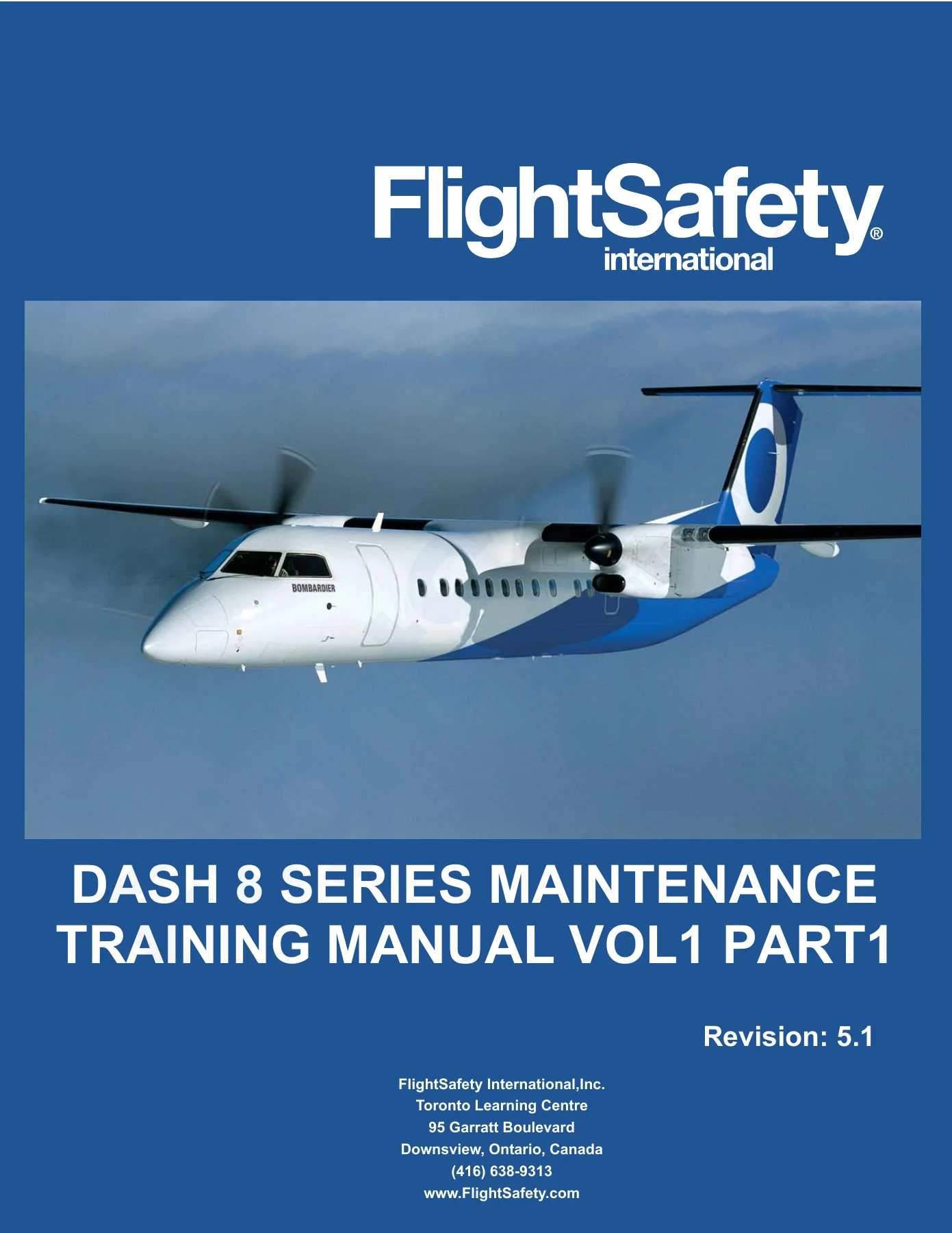
FlightSafety International Dash 8 Series Maintenance Training Manual, Volume 1 Part 1, Revision 5.1 – a 525-page illustrated PDF covering air conditioning, avionics, electrical power and fire protection across the DHC-8 Series 100/100A, 200, 300 and 300A.
Description
Dash 8 Series Maintenance Training Manual Volume 1 Part 1 – FlightSafety
The Dash 8 Series Maintenance Training Manual Volume 1 Part 1 is the FlightSafety International training text used to take maintenance technicians through the environmental, avionics, electrical and fire protection systems of the DHC-8 family. Revision 5.1 covers the Series 100, 100A, 200, 300 and 300A airframes, with the air conditioning material split into dedicated chapters for the 100/100A, 300A and 200 so the differences between the PW-120 and PW-123 installations stay where they belong. It is a training document rather than an OEM maintenance manual – the publisher states clearly that the material is intended for familiarization and instructional purposes and that the aircraft manufacturer’s own publications take precedence wherever the two differ.
File Details
- Manual type: Maintenance Training Manual
- Aircraft: de Havilland DHC-8 (Dash 8)
- Models covered: Series 100, 100A, 200, 300, 300A
- Engines covered: Pratt & Whitney PW-120 (Series 100), PW-123 (Series 300)
- Volume: Volume 1, Part 1
- Revision: 5.1
- Publisher: FlightSafety International, Inc. – Toronto Learning Centre
- Language: English
- Page count: 525 pages
- File format: PDF
Chapters Covered
- Introduction
- ATA 100
- Aircraft General
- Air Conditioning (Series 100/100A)
- Air Conditioning (Series 300A)
- Air Conditioning (Series 200)
- Avionics
- Electrical Power
- Fire Protection
Part 1 carries the sequence from the opening introduction through the fire protection chapter, matching the ATA 100 chapter numbers printed on the divider tabs.
Introduction and ATA 100
The opening chapters explain how the ATA 100 documentation format is laid out and how to work inside it. The standard numbering system is broken down element by element – chapter, section, subject and unit – using a worked example, and the difference between a system-level number and a component-level number is spelled out. Revision handling is covered in detail, including the white normal revisions and the yellow temporary revisions, the Record of Revisions, the Temporary Revision Index and the separate Customized Chapters Volume used for avionics and furnishings. A list of associated publications is included, covering the aircraft operating data, flight manual, maintenance manual, engine rigging manual, ramp servicing manual, tools and equipment manual, wiring diagrams manual, structural rigging manual, illustrated parts manual, component maintenance manual, maintenance program manual and weight and balance manual. The chapter closes with the Dash 8 Scheduled Maintenance Program and the MSG-3 logic behind it, the split between systems and structures analysis, airworthiness limitations, and what a repair to damage tolerant structure means for inspection intervals.
Aircraft General (ATA 5 through 12)
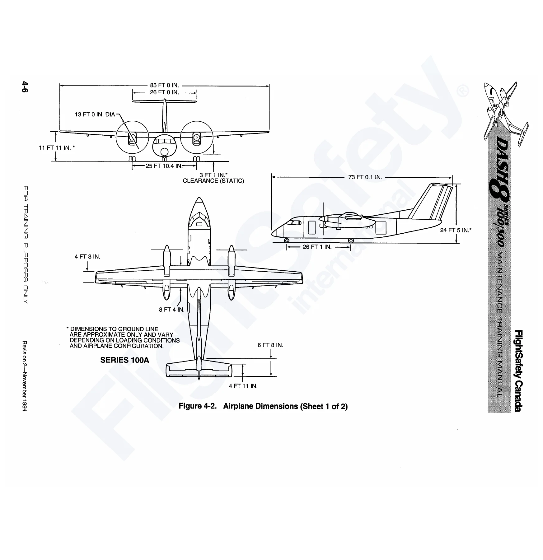
This is the ground handling and servicing block. Time limits and maintenance checks open with the unscheduled inspection guidance – bird strike, lightning strike, hard or overweight landing, turbulence, VMO exceedance and rough ground handling – followed by the scheduled check intervals. Dimensions and areas cover the airplane coordinate system with its X, Y and Z axes and the separate points of origin for the Series 100 and Series 300 airframes, the eight major airplane zones from lower fuselage through doors and windows, and the access panel and door identification scheme. Lifting and shoring, leveling and weighing, towing and taxiing, parking and mooring are all presented with the cautions and warnings that go with them, including towing turning limits and the flat-tire movement precautions. Servicing covers approved fuels and tank capacities, hydraulic fluid handling and reservoir filling, landing gear shock strut servicing with MIL-H-5606 fluid and nitrogen, crew and portable oxygen, the toilet unit and waste drains, the optional wash water system, engine oil level checking, APU oil, aircraft cleaning and cold weather protection.
Air Conditioning (Chapters 21, 21A and 21B)
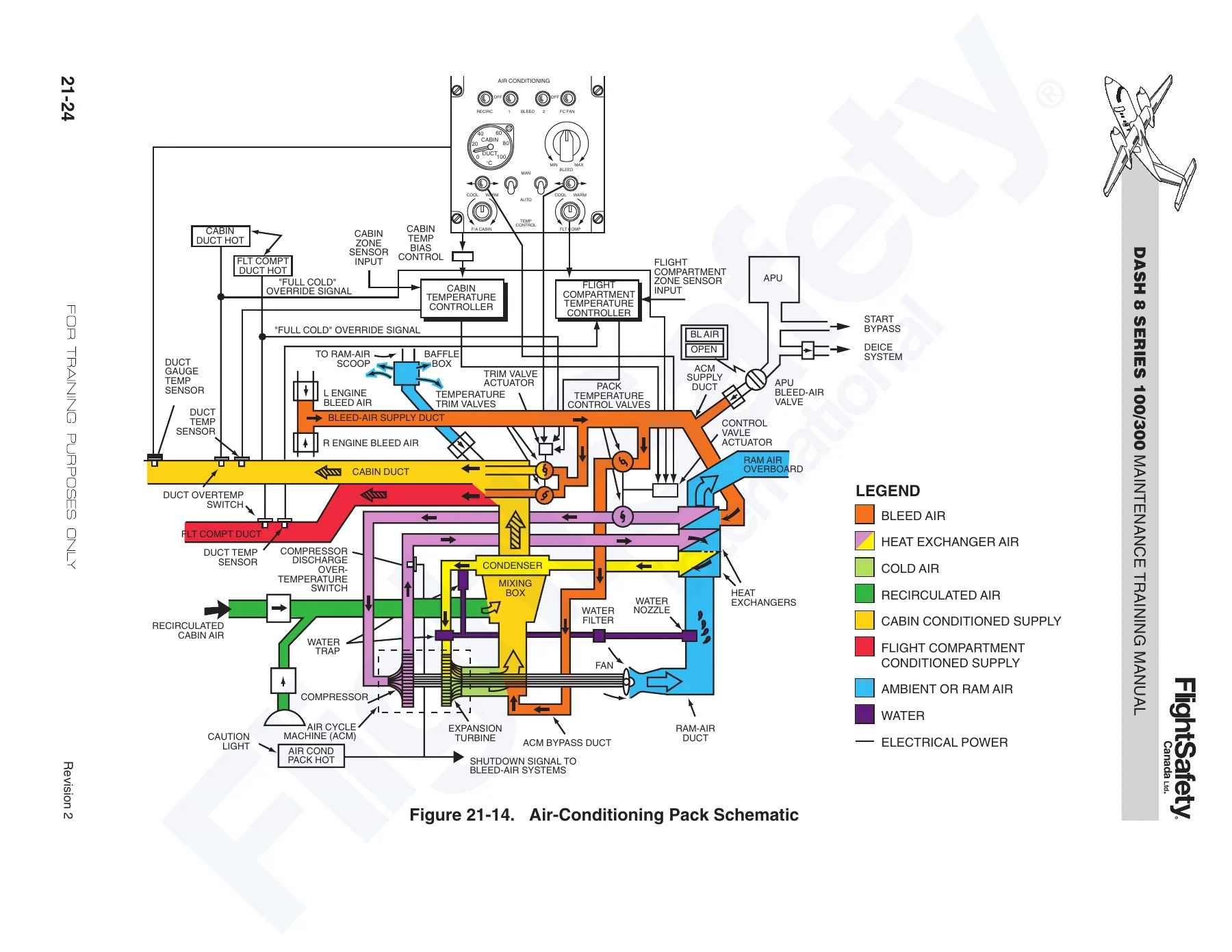
This is the largest block in the file and the reason the air conditioning material is split three ways. The Series 100/100A chapter works through the bleed-air system component by component – high-pressure bleed shutoff valve, high-pressure switch, choking venturis, low-pressure bleed check valve, pressure regulator and shutoff valve, and the bleed-air overtemperature switch – before moving into the air-conditioning pack, the air cycle machine, the primary and secondary heat exchangers, the condenser/mixer, the pack temperature control valves and the flight compartment trim valves. Temperature control is covered in both automatic and manual modes, with the duct and zone sensors, the temperature controllers, the cabin temperature bias control and the duct overheat sequence. Conditioned air distribution is given separate treatment for the pre-1990 interior and the 1990 interior, along with the gasper air system, the air recirculation system and avionics compartment cooling. Pressurization covers the normal and safety outflow valves, the selector and indicator panels, the cabin pressure computer and the various dump methods, supported by a pressurization envelope chart. The 300A chapter repeats the same ground with the two-pack, two-PRSOV arrangement, the handling bleed valve and precooler, the set-down limiter and shuttle valve, and the Mod 8/1656 simplified bleed flow control. The 200 chapter covers the single-pack configuration with its own bleed-air and pressurization layout.
Avionics (Chapter 22)
Avionics opens with the pitot-static system – two pitot heads, two static vent plates with three ports each, and the alternate static source selection – then moves into the air data system with its dual ADCs, barometric altimeters and altitude preselector/alerter. Attitude and heading reference is covered in detail, including the AHRU, the flux valves, the AHRS controller with its DG, BASIC, SLAVE and AUX PR annunciators, and the power requirements. The electromechanical flight instruments get their own treatment with the ADI, radio altimeter, HSI and RMI, followed by the optional electronic flight instrument system, its EADI and EHSI symbology, the display controllers and the symbol generator failure indication. The Sperry digital automatic flight control system chapter works through the DFZ-8000 and SPZ-8000 architecture, the autopilot modes, the AFCS controller, the flight director modes, the advisory display, the servoactuators and the AFCS failure annunciations. Navigation equipment covers the VOR, marker beacon, DME and ADF receivers. Communications covers the audio integrating system, service interphone, VHF COMM and VHF NAV radios, emergency operation and the passenger address system. The miscellaneous equipment block covers the transponder, cockpit voice recorder, flight data recorder, ground proximity warning system, emergency locator transmitter, weather radar, flight management system and TCAS, with the VSI/TRA traffic display symbology.
Electrical Power (Chapter 24)
The electrical chapter opens with the main and auxiliary nickel-cadmium batteries, their venting system and the battery temperature monitor with its display and overheat sensors. The DC power system is then taken apart section by section: the starter-generators and their generator control units, the DC contactor box and its relay schedule, the generator control switches, the transformer-rectifier units, the automatic bus-tie logic, the bus bar protection unit and its fault reset, the DC external power system and the DC power monitor panel. Engine starting is given a full sequence description, covering battery-only starting, cross-starting and starting with external power connected. The AC power system covers variable-frequency generation from the two engine-driven AC generators, the AC contactor boxes and current transformers, the AC generator control units, the fixed-frequency 400 Hz inverter system with its paralleling control box and 26-volt transformers, AC external power and the AC power monitor. The chapter closes with circuit protection and battery removal and installation considerations.
Fire Protection (Chapter 26)
Fire protection covers engine fire detection with the dual continuous-loop sensor loops and responders, the fire detection control units, the fire protection panel with its loop selection and fault lights, and the full alarm, loop fault and test sequences. Engine fire extinguishing is covered with the two extinguisher bottles, squibs, discharge valves, distribution lines, the yellow system discharge indicator and the red thermal discharge indicator. The lavatory smoke detection system is presented in both the Mod 8/0266 form and the Series 300 form, followed by the automatic lavatory fire extinguisher. Baggage compartment smoke detection, portable fire extinguishers for the Series 100 and Series 300, and the maintenance practices, servicing, inspection, fault analysis and functional check guidance close the chapter.
What This Dash 8 Training Manual Lets You Do
Working through this Dash 8 maintenance training manual gives a technician the system-level understanding that makes the OEM documentation usable. You can follow the bleed-air system from the engine port to the pack and understand what each valve, switch and venturi is doing and why; trace a pressurization fault from the outflow valve back through the torque motor, the venturi ejector and the cabin pressure computer; work the autopilot mode logic on the AFCS controller and read the advisory display messages correctly; and follow the DC bus-tie and bus bar protection logic well enough to know what a MAIN BATTERY or DC BUS caution light is actually telling you before you start pulling panels.
The training text is written to explain operation, not just list part numbers. That matters when a fault only appears in one mode, at one altitude, or after a specific sequence of switch selections – the kind of intermittent that a fault code will not point at. Knowing how the system is supposed to sequence gives you a place to start.
IMAGES PREVIEW
Because the file is delivered as an instant PDF download, there is no shipping and no waiting. It opens on a laptop, tablet or phone, and any page can be printed for a binder or a hangar copy. Buyers should note that this is a training manual, not an OEM maintenance manual – it is intended for familiarization and instructional use, and the aircraft manufacturer’s own publications take precedence wherever the two differ.

Reviews
There are no reviews yet.