Dell XPS 8920 Desktop Service Manual Repair Guide D24M PDF
Original price was: $95.00.$18.95Current price is: $18.95.
Complete Dell service manual for XPS 8920 gaming desktop computer (Regulatory Model D24M/D24M001). Comprehensive technical documentation covering component removal and replacement procedures including hard drives, SSDs, memory modules, graphics cards, processor, cooling system, power supply, and system board. Features detailed step-by-step instructions with illustrations, safety precautions, screw identification, troubleshooting guides, BIOS setup, and system specifications. Essential reference for computer technicians and IT professionals.
Description
Dell XPS 8920 Desktop Service Manual Repair Guide D24M Workshop PDF DOWNLOAD
DESCRIPTION
Dell XPS 8920 Desktop Official Service Manual
This comprehensive factory service manual provides complete technical documentation for the Dell XPS 8920 high-performance desktop computer (Regulatory Model D24M). Essential reference for computer repair technicians, IT professionals, and service centers performing maintenance, upgrades, and component replacements on this premium gaming and workstation desktop.
📋 FILE DETAILS
| Specification | Details |
|---|---|
| Manual Name | Dell XPS 8920 Service Manual |
| Computer Model | XPS 8920 |
| Regulatory Model | D24M |
| Regulatory Type | D24M001 |
| Revision | A04 (June 2020) |
| Pages | 102 pages |
| PDF Quality | High-resolution professional documentation |
| File Size | 14.5 MB |
| Language | English (en-US) |
| Publisher | Dell Inc. |
💻 DELL XPS 8920 DESKTOP OVERVIEW
High-Performance Features:
- Gaming Desktop – Optimized for high-end gaming
- Intel Processor Platform – Supports latest Intel CPUs
- Dedicated Graphics – NVIDIA GeForce GTX support
- Multiple Storage Options – HDD, SSD, and M.2 configurations
- Expandable Memory – 4 DIMM slots for RAM expansion
- PCIe Expansion – Multiple slots for upgrades
- Tool-less Design – Easy component access
Target Market:
- Gaming enthusiasts
- Content creators
- Power users
- Small business workstations
- Professional applications
📖 COMPREHENSIVE SERVICE MANUAL CONTENTS
CHAPTER 1: Before Working Inside Your Computer
Pre-Service Requirements:
- Before You Begin – Initial preparation steps
- Safety Instructions:
- ESD (Electrostatic Discharge) precautions
- Proper grounding procedures
- Power disconnection requirements
- Component handling guidelines
- Personal safety measures
Tools and Equipment:
- Recommended Tools:
- Phillips screwdrivers
- Flat-head screwdrivers
- Anti-static wrist strap
- Plastic scribe or spudger
- Work surface preparation
Hardware Reference:
- Screw List – Complete screw identification guide
- Screw types used
- Thread sizes
- Length specifications
- Torque requirements
- Location references
CHAPTER 2: After Working Inside Your Computer
Post-Service Procedures:
- Power-on verification
- Component detection checks
- BIOS/UEFI verification
- Operating system boot testing
- Hardware functionality testing
- Cable and connector verification
CHAPTER 3: Technical Overview
System Architecture:
- Inside View of Your Computer:
- Component layout diagram
- Major subsystem identification
- Cable routing overview
- Cooling airflow paths
System Board Components:
- Motherboard Layout Diagram:
- Processor socket location
- Memory slot positions (DIMM1-4)
- PCIe slot configuration
- M.2 SSD slot location
- Power connectors
- Fan headers (CPU_FAN, SYS_FAN)
- Front panel connectors
- USB headers
- SATA ports
- CMOS battery location
- Chipset identification
CHAPTERS 4-5: Right-Side Cover
Removal Procedure:
- Release mechanism location
- Tab disengagement procedure
- Panel removal technique
- Cable management during removal
Replacement Procedure:
- Proper alignment techniques
- Tab engagement sequence
- Secure closure verification
CHAPTERS 6-7: Front Bezel
Prerequisites: Right-side cover removal
Removal Procedure:
- Clip location identification
- Release tab procedure
- Front I/O cable handling
- Bezel separation technique
Replacement Procedure:
- Cable reconnection
- Clip engagement
- Secure attachment verification
Post-requisites: Cover reassembly
CHAPTERS 8-9: Optical Drive
Prerequisites: Front bezel removal
Removal Procedure:
- Power and data cable disconnection
- Mounting screw removal
- Bracket disengagement
- Drive extraction from bay
Replacement Procedure:
- Drive installation in bay
- Mounting screw installation
- Cable reconnection
- Functional verification
CHAPTERS 10-13: Top and Bottom Covers
Top Cover:
- Prerequisites: Front bezel removal
- Tab release procedure
- Cover lifting technique
- Cable clearance
Bottom Cover:
- Access to underside components
- Screw locations
- Cover removal sequence
- Dust filter cleaning access
CHAPTERS 14-17: Primary Hard Drive
Two Installation Methods:
Method 1: With Tabs (Tool-less):
- Tab-release mechanism
- Drive caddy removal
- SATA cable disconnection
- Quick-release installation
Method 2: With Screws:
- Screw identification
- Mounting bracket removal
- Drive extraction
- Secure installation
Drive Specifications:
- 3.5″ SATA HDD support
- Hot-swap capability
- Cable routing guidelines
CHAPTERS 18-19: Secondary Hard Drive
Additional Storage Bay:
- Secondary drive location
- Independent mounting system
- Separate SATA connection
- Power cable routing
- Multi-drive configuration
CHAPTERS 20-21: Solid-State Drive (SSD)
M.2 SSD Installation:
- Prerequisites: Cover removal
- M.2 slot identification
- Mounting screw removal
- SSD insertion procedure
- Thermal pad placement
- Securing clip engagement
SSD Support:
- M.2 2280 form factor
- NVMe PCIe interface
- SATA M.2 support
- Boot drive configuration
CHAPTERS 22-23: Power Supply Unit (PSU)
Prerequisites:
- Multiple cover removals
- Cable disconnection
Removal Procedure:
- Internal cable disconnection sequence
- Motherboard power connector removal
- Graphics card power removal
- Storage device power removal
- Mounting screw identification
- PSU extraction from chassis
Replacement Procedure:
- PSU positioning
- Mounting screw installation
- Cable routing and connection
- Power rating verification
- Modular cable management
PSU Specifications:
- Wattage options
- ATX form factor
- 80+ efficiency rating
- Modular cable system
CHAPTERS 24-25: Coin-Cell Battery (CMOS)
Prerequisites: Cover access
Battery Removal:
- Battery location on motherboard
- Retaining clip release
- Battery extraction technique
- Polarity identification
Battery Replacement:
- CR2032 specification
- Correct polarity orientation
- Secure clip engagement
- BIOS settings preservation
CMOS Reset:
- Settings loss implications
- Date/time reset
- BIOS reconfiguration needs
CHAPTERS 26-29: Graphics Cards
Standard Graphics Card (Chapters 26-27):
- Prerequisites: Side cover removal
- PCIe slot locking mechanism
- Power connector disconnection
- Mounting bracket screw removal
- Card extraction procedure
Full-Length Graphics Cards (Chapters 28-29):
- Support bracket requirement
- Multiple power connectors
- Extended card handling
- Clearance verification
Graphics Card Support:
- PCIe x16 slot
- Multiple slot configurations
- NVIDIA GeForce GTX series
- AMD Radeon support
- Power requirements (6-pin, 8-pin)
- Physical clearance dimensions
CHAPTERS 30-31: Memory Modules (RAM)
Prerequisites: Cover removal for access
Memory Module Removal:
- Memory Module Slots: DIMM1, DIMM2, DIMM3, DIMM4
- Securing clip release procedure
- Proper module handling (edges only)
- Module extraction technique
- Anti-static precautions
Memory Module Installation:
- Slot identification and population order
- Notch alignment with slot tab
- Proper insertion angle
- Clip engagement verification
- Dual-channel configuration
Memory Specifications:
- DDR4 UDIMM support
- Maximum capacity
- Speed ratings supported
- Dual-channel optimization
- Compatible module types
CHAPTERS 32-39: System Board and Front I/O
System Board Removal:
- Complete disassembly required
- Cable disconnection checklist
- Mounting standoff locations
- Board extraction procedure
Front I/O Panel:
- USB port connections
- Audio jack connections
- Power button
- LED indicators
- Card reader (if equipped)
I/O Shield:
- Rear panel I/O connections
- Shield removal and installation
- Port alignment
CHAPTERS 40-41: Processor Fan and Heat Sink
Cooling System Removal:
- Prerequisites: Multiple components
- Fan power connector disconnection
- Captive screw loosening sequence
- Thermal paste inspection
- Heat sink removal technique
- Cleaning procedures
Cooling System Installation:
- Thermal paste application
- Heat sink positioning
- Screw tightening sequence (diagonal pattern)
- Even pressure distribution
- Fan header connection
- Airflow direction verification
Cooling Specifications:
- Stock Intel cooler compatibility
- Third-party cooler clearance
- Thermal design power (TDP) support
- Fan speed control (PWM)
CHAPTERS 42-43: Speaker
Internal Speaker:
- Speaker location
- Wire routing
- Connector identification
- Replacement procedure
CHAPTERS 44-45: Processor (CPU)
Prerequisites:
- Fan and heat sink removal
- Thermal paste removal
Processor Removal:
- Socket Identification:
- Intel LGA socket type
- Socket cover mechanism
- Pin protection
Removal Procedure:
- Processor release latch operation
- Lever lift procedure
- Load plate opening
- Processor extraction (edges only)
- Pin inspection
Processor Installation:
- Socket pin inspection
- Processor orientation (corner marking)
- Gentle processor placement
- Load plate closure
- Latch securing
- Thermal paste application
CPU Specifications:
- Intel Core processor support (6th/7th gen)
- Socket compatibility
- TDP ratings
- Integrated graphics option
- Overclocking capability (K-series)
CHAPTERS 46-49: System Board Replacement
Complete Motherboard Service:
- Full system disassembly
- Component transfer procedures
- BIOS chip handling
- Board alignment
- I/O shield alignment
- All cable reconnections
CHAPTERS 50-61: Additional Components
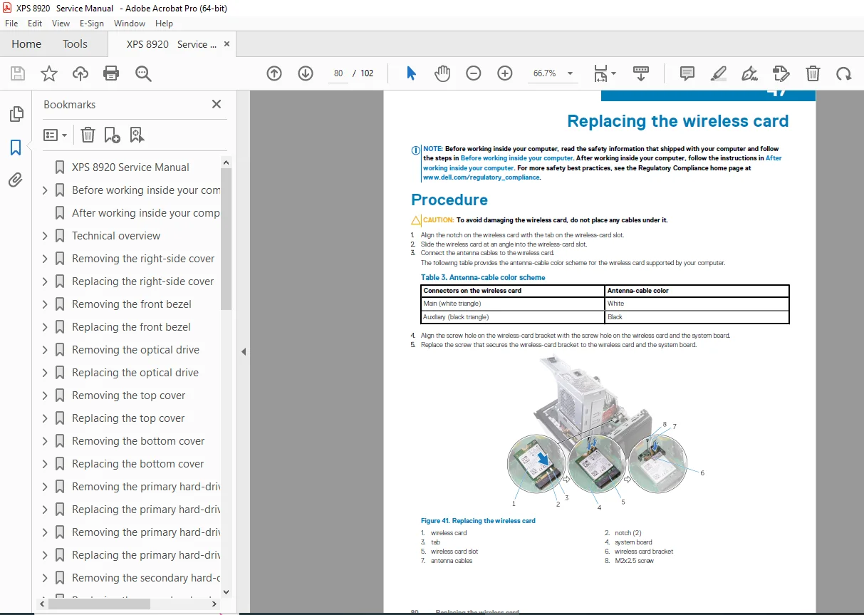
Wireless Card:
- M.2 wireless module
- Antenna cable routing
- WiFi/Bluetooth functionality
Intrusion Switch:
- Chassis intrusion detection
- Security feature
- BIOS alert configuration
VGA Daughter Board:
- Video output expansion
- Legacy VGA support
CHAPTER 62: System Setup (BIOS/UEFI)
BIOS Configuration:
- Entering system setup (F2 key)
- Boot sequence configuration
- SATA operation modes (AHCI/RAID)
- Secure Boot settings
- Legacy/UEFI boot options
- Virtualization settings
- Power management
- Password protection
- System information display
BIOS Navigation:
- Menu structure
- Option modification
- Settings save and exit
- Default restoration
CHAPTER 63: Troubleshooting
Diagnostic Procedures:
Power Issues:
- No power symptoms
- Power LED diagnostics
- PSU testing
- Motherboard power verification
POST Issues:
- Beep code interpretation
- LED error codes
- No display troubleshooting
- Memory error diagnosis
Boot Problems:
- Boot device detection
- Operating system loading issues
- BIOS corruption recovery
Hardware Diagnostics:
- Built-in diagnostics access
- Component testing procedures
- Error code interpretation
Common Problems:
- System won’t power on
- No display output
- Memory not detected
- Storage device not recognized
- Overheating issues
- USB device problems
- Audio issues
- Network connectivity problems
CHAPTER 64: Specifications
Complete System Specifications:
Processor:
- Supported Intel models
- Socket type
- Maximum TDP
Chipset:
- Intel chipset model
- Feature set
Memory:
- Type: DDR4 UDIMM
- Slots: 4 x DIMM
- Maximum capacity
- Supported speeds
- Dual-channel support
Storage:
- SATA ports available
- M.2 slot specifications
- Supported drive types
- RAID capabilities
Graphics:
- Integrated graphics (CPU-dependent)
- PCIe x16 slot for discrete GPU
- Maximum GPU power support
Expansion:
- PCIe slot configuration
- PCI slot (legacy)
- M.2 slots
Connectivity:
- USB ports (front and rear)
- USB 3.1/3.0/2.0 breakdown
- Ethernet port
- Audio jacks
- Display outputs
Power Supply:
- Wattage options
- Efficiency rating
- Form factor
Physical:
- Dimensions
- Weight
- Chassis type
Operating System:
- Windows support
- Linux compatibility
🔧 KEY SERVICE FEATURES
Modular Design:
- Tool-less components where possible
- Easy cable management
- Accessible interior layout
- Clear component labeling
Upgradeability:
- CPU upgradeable (socket compatibility)
- Memory expandable to maximum capacity
- Multiple storage bay options
- Graphics card upgradeable
- Power supply replaceable
Service-Friendly:
- Side panel quick release
- Color-coded cables
- Keyed connectors (prevent incorrect installation)
- Clear screw identification
- Logical disassembly sequence
💡 MAINTENANCE CAPABILITIES
User-Serviceable Components:
- Memory modules (RAM)
- Storage drives (HDD/SSD)
- Graphics card
- Optical drive
- CMOS battery
- Expansion cards
Technician-Level Service:
- Processor replacement
- Heat sink servicing
- Motherboard replacement
- Power supply replacement
- Advanced troubleshooting
👥 ESSENTIAL FOR IT PROFESSIONALS
This manual is critical for:
- Computer Repair Technicians performing hardware repairs
- IT Support Staff maintaining desktop systems
- System Builders assembling custom configurations
- Warranty Service Centers conducting authorized repairs
- Corporate IT Departments managing fleet deployments
- Technical Training Programs teaching computer hardware
- Advanced Users performing upgrades and maintenance
🎮 GAMING AND WORKSTATION APPLICATIONS
Use Cases:
- High-end PC gaming
- Video editing and rendering
- 3D modeling and CAD
- Software development
- Virtual machine hosting
- Content creation
- Graphic design
- Data analysis
⚙️ COMPONENT COMPATIBILITY
Processor Support:
- Intel 6th generation (Skylake)
- Intel 7th generation (Kaby Lake)
- Socket LGA 1151
Memory Support:
- DDR4 non-ECC UDIMM
- 2133 MHz, 2400 MHz speeds
- Maximum 64GB (4 x 16GB)
Storage Options:
- 3.5″ SATA HDD
- 2.5″ SATA SSD
- M.2 NVMe SSD
- M.2 SATA SSD
Graphics Support:
- NVIDIA GeForce GTX series
- AMD Radeon RX series
- PCIe 3.0 x16 interface
🛠️ ILLUSTRATED PROCEDURES
Visual Documentation:
- High-quality photographs
- Component identification callouts
- Step-by-step visual guides
- Cable routing diagrams
- Connector close-ups
Clear Instructions:
- Numbered step procedures
- Prerequisites listed
- Post-requisites specified
- Safety warnings highlighted
- Caution notes for critical steps
📐 SAFETY AND HANDLING
ESD Protection:
- Anti-static precautions
- Grounding requirements
- Proper component handling
- Workspace preparation
Component Care:
- Processor: Hold by edges only
- Memory: Avoid touching contacts
- Graphics card: Handle by bracket
- Drives: Avoid dropping or shocking
🔍 TECHNICAL SUPPORT
Dell Resources:
- Service tag identification
- Express service code
- Warranty information
- Technical support contacts
- Driver and download portal
- Knowledge base access
⚡ DELL XPS QUALITY
Premium Desktop Features:
- High-quality components
- Robust chassis construction
- Efficient cooling design
- Cable management system
- Dust filtration
- Professional aesthetics
⚡ INSTANT DOWNLOAD – SERVICE DELL XPS DESKTOPS PROFESSIONALLY! This comprehensive 102-page Dell factory service manual provides complete disassembly and reassembly procedures for the XPS 8920 gaming desktop. From simple component upgrades to complete system rebuilds, every procedure is documented with detailed instructions and professional photographs. Download immediately and gain expert-level knowledge for Dell XPS 8920 service and repair!
Pricing Rationale:
- 102 pages of technical documentation
- Consumer desktop computer (not server/enterprise)
- Modern system (2017-2020 era)
- Complete disassembly procedures
- All major components covered
- Official Dell service manual
- High-resolution illustrations
- BIOS setup and troubleshooting included
- Gaming/enthusiast desktop market
- DIY upgrade community resource
- IT professional reference
- Recent revision (June 2020)